Table of Contents
Advertisement
Advertisement
Table of Contents

Related Manuals for Welch Allyn SCANTEAM 8300


Summary of Contents for Welch Allyn SCANTEAM 8300
- Page 1 Check Reader 8300/8310...
- Page 2 E 1998 Welch Allyn, Inc. All rights reserved.
-
Page 4: Statement Of Agency Compliance
Consult the dealer or an experienced radio or television technician for help. Caution: Any changes or modifications made to this device that are not expressly approved by Welch Allyn, Inc. may void the user’s authority to operate the equipment. Note: To maintain compliance with FCC Rules and Regulations, cables connected to this device must be shielded cables, in which the cable shield wire(s) have been grounded (tied) to the connector shell. - Page 5 Dallam Court Dallam Lane Warrington, Cheshire WA2 7LT England Welch Allyn shall not be liable for use of our product with equipment (i.e., power supplies, personal computers, etc.) that is not CE marked and does not comply with the Low Voltage Directive.
-
Page 6: Limited Warranty
(2) years from the time of shipment by Welch Allyn, Inc. to the user at the time it is purchased from any of Welch Allyn Inc.’s Authorized Distributors. Any attempt on the part of the user to disassemble or service the equipment shall void the warranty. - Page 7 Limited Warranty...
-
Page 8: Table Of Contents
..... . 2–1 SCANTEAM 8300 Product Illustrations ..2–2 SCANTEAM 8300/8310 Set-up and Installation 2–5 2.4.1 Unpacking the Check Reader ..2–5 Set-up . - Page 9 ..... 3–6 SCANTEAM 8300/8310 Operating Power Requirements ....
-
Page 10: Section Page
Host Port Interface Compatibility ... . . 4–1 4.2.1 SCANTEAM 8300-1 IBM 468X/469X and Retail Configuration ... . . 4–2 4.2.2... - Page 11 ....5–7 5.6.1 SCANTEAM 8300 LED Display Error Codes ......
- Page 12 Appendix A SCANTEAM 8310 Information Section Page Chapter Description ......A–1 Physical Specifications ..... . A–1 SCANTEAM 8310 Product Illustrations .
- Page 13 (Shown with Optional Integrated MSR) ....2–2 Figure 2 Rear View of the SCANTEAM 8300 (Shown with Optional Integrated MSR and Scanner Port) ........
-
Page 14: Introduction
In addition to providing MICR character recognition, the SCANTEAM 8300 provides interface port expansion to the host device to which it is attached. The SCANTEAM 8300 allows MICR, magnetic stripe reader (MSR), bar code scanner, and up to two channels of auxiliary RS 232 data to be concentrated and attached to a single physical interface port or keyboard interface on a host device. -
Page 15: Operational Example
1.2 Operational Example The SCANTEAM 8300/8310 can be used by an operator to automatically acquire and transfer data from the MICR line on a personal check to the POS terminal which is being used for a retail transaction. The SCANTEAM 8300/8310 is faster than manual keying and eliminates errors which can be made when keying data manually. -
Page 16: Chapter 2 Physical Description, Illustrations
Note: Please refer to Appendix A for Physical Specifications and Set-up of the SCANTEAM 8310. All other information in this chapter is applicable to both the SCANTEAM 8300 and the SCANTEAM 8310. 2.2 Physical Specifications Case Material Type: ABS Plastic enclosure... -
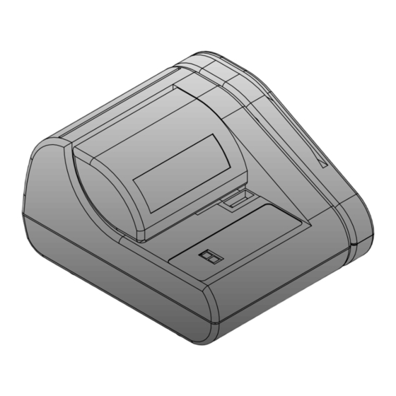
Page 17: Scanteam 8300 Product Illustrations
2.3 SCANTEAM 8300 Product Illustrations 0.20” Gap (5.08 mm) Integrated Magnetic Stripe Card Reader 7-Segment Status Display Figure 1 SCANTEAM 8300 (Shown with Optional Integrated MSR) 2–2 Physical Description, Illustrations & Operation... - Page 18 External Host Power 3-Track Interface Pack Integrated Magnetic Stripe Port Connector Magnetic Stripe Card Reader Port Card Reader Figure 2 Rear View of the SCANTEAM 8300 (Shown with Optional Integrated MSR and Scanner Port) Physical Description, Illustrations & Operation 2–3...
- Page 19 RS-232 Port: Aux 2 RS-232 Port: Aux 1 Wall Mount Keyholes Figure 3 Bottom View of the SCANTEAM 8300 (Shown with Optional Integrated MSR and Second Auxiliary Port) 2–4 Physical Description, Illustrations & Operation...
-
Page 20: Scanteam 8300/8310 Set-Up And Installation
0.20 inches. To insure proper operation and prevent possible damage to the SCANTEAM 8300 check reader or terminal, you should perform the following installation procedures in the sequence in which they are presented. -
Page 21: Set-Up
Note: SCANTEAM 8300 Power Architecture: The SCANTEAM 8300 is shipped from the factory with an internal jumper set to allow the check reader to operate from power supplied by a host device through the DB-15 host interface connector. Refer to section 2.5.2 on page 2–9 if you plan to operate the SCANTEAM... - Page 22 Welch Allyn Interface Products Work Center (IPWC) Interface/Cable Matrix, part number 11208627, document.) (3) Attach the SCANTEAM 8300 interface cable to the host terminal. (4) Plug the 15 pin male connector of the interface cable into the 15 pin female connector located on the back panel of the 8300.
- Page 23 SCANTEAM 8300 rear panel. Note: If you have ordered the SCANTEAM 8300 check reader with the integrated magnetic stripe card reader option installed, the output cable from the integrated MSR will be attached to the MSR port on the SCANTEAM 8300 rear panel at the factory.
-
Page 24: Externally-Powered Installations
2.5.2 Externally-Powered Installations Usage Restrictions The SCANTEAM 8300 may be operated by power supplied by an external wall or desk mount power pack only under either of the following conditions: Use of External Power (EP) Host Interface Cable: If the host interface cable used to attach the SCANTEAM... -
Page 25: Figure 4 Disassembly Of The Scanteam 8300
When using an external power supply in conjunction with a host interface cable which provides host power, you must make a jumper change to a 3 pin header on the SCANTEAM 8300's PC board. (The default configuration assumes a host powered application.) The following illustrations show the disassembly of... -
Page 26: Figure 5 Scanteam 8300 Power Jumper Placement
Once the hood is removed, the power jumpers on the JP2, JP4 and JP3 3 pin headers are accessible using small, needle nosed pliers. Figure 5 SCANTEAM 8300 Power Jumper Placement Physical Description, Illustrations & Operation 2–11... -
Page 27: Figure 6 Scanteam 8300 Pc Board
Please see page 2–13 for optional power jumper placements. Note: This PC board complies with European CE standards, and is contained in SCANTEAM 8300 products which are marked “CE” on the bottom product label. Please contact Welch Allyn technical support for details concerning jumper position and placement for products which do not contain the CE mark. -
Page 28: Figure 7 Optional Power Jumper Placement For The Scanteam 8300 Pc Board
(2) Locate the interface cable and verify its part number. (Cable part numbers are provided in the Welch Allyn Interface Products Work Center (IPWC) Interface/Cable Matrix document.) (3) Attach the SCANTEAM 8300 interface cable to the host terminal. Physical Description, Illustrations & Operation 2–13... - Page 29 Welch Allyn under part number 8300WALL.") Caution: You must keep the SCANTEAM 8300/8310 away from sources of EMI/EMC radiation, such as power supplies. Note: You can program the 8300/8310 to detect magnetic interference.
- Page 30 SCANTEAM 8300 issues a single beep and displays an upper case O" on its status display indicating the SCANTEAM 8300 is in a non error condition idle state. Caution: Do not try to enter data until the host terminal has fully initialized.
-
Page 31: Figure 8 Feeding A Micr Document
2.6 Check Reading Procedure Once the SCANTEAM 8300/8310 Check Reader has been properly installed and configured with its host device, you may read MICR documents. The SCANTEAM 8300/8310 contains sensors which detect the proper physical placement of a check (or other MICR encoded document) in the SCANTEAM 8300/8310 Check Reader. - Page 32 MICR reading parameters during its first MICR read process. If these average parameters do not result in a good read, the SCANTEAM 8300 displays a C" on its LED status display, and adjusts the MICR reading parameters based on the data taken during that first read.
- Page 33 2–18 Physical Description, Illustrations & Operation...
-
Page 34: Chapter 3 Hardware Interface Description
Note: Please refer to Appendix A for the Hardware Interface Description for the SCANTEAM 8310. The Operating Power Requirements (page 3–8) are applicable to both the SCANTEAM 8300 and the SCANTEAM 8310. 3.2 DB-15F Host Port Connector The female 15 pin sub miniature D host port connector signals are unique for each version of the product (SCANTEAM 8300 1, 2, 3, and 4). -
Page 35: Model 8300-1: Db-15 Pin Assignment
3.2.1 Model 8300-1: DB-15 Pin Assignment Pin # Signal Logic ground VCC (+ 5V) D6 (OCR) D4 (OCR) Keyboard wedge data (Input)/EOT (OCR) Keyboard wedge Clk (Input)/Edit Check (OCR) RDATA (OCIA) Data ready (OCR)/5B RX/TX Vin (+ 12V) Bootstrap D5 (OCR) D3 (OCR) Keyboard wedge term data (Output)/D2 (OCR) Keyboard wedge term Clk (Output)/D1 (OCR)/CLKIDATA (OCIA) -
Page 36: Model 8300-2: Db-15 Pin Assignment
3.2.2 Model 8300-2: DB-15 Pin Assignment Pin # Signal Logic ground VCC (+ 5V) D6 (OCR) D4 (OCR) Keyboard wedge data (Input)/EOT (OCR) Keyboard wedge Clk (Input)/Edit Check (OCR) RDATA (OCIA) Data ready (OCR) Vin (+ 12V) Bootstrap D5 (OCR) D3 (OCR) Keyboard wedge term data (Output)/D2 (OCR) Keyboard wedge term Clk (Output)/D1 (OCR)/CLKIDATA (OCIA) -
Page 37: Model 8300-4: Db-15 Pin Assignment
3.2.3 Model 8300-4: DB-15 Pin Assignment Pin # Signal Logic ground VCC (+ 5V) RXD input (RS-232) CTS input (RS-232) Keyboard wedge data (Input) Keyboard wedge Clk (Input) RDATA (OCIA) Data ready (OCR)/5B RX/TX Vin (+ 12V) Bootstrap TXD output (RS-232) RTS output (RS-232) Keyboard wedge term data (Output) Keyboard wedge term Clk (Output)/D1 (OCIA) -
Page 38: Auxiliary Rs-232 Ports
3.3 Auxiliary RS-232 Ports Note: The base level SCANTEAM 8300 is supplied with a single RS-232 Aux port. A second RS-232 port is available only as a factory installed option. The pinouts for pin positions 1 through 6 of the RJ 11 modular... -
Page 39: Magnetic Stripe Card Reader Port
3.5 Bar Code Scanner Port An optional interface connector (a factory installed option) installed in the rear panel of the SCANTEAM 8300 supports the attachment of a + 5 volt non decoded output scanner. The SCANTEAM 8300 is compatible with all Welch Allyn contact and non contact bar code scanners, including bar code contact wands, lasers, CCDs, and swipe readers. - Page 40 DB 15 pin 9 (typically +12 VDC) to be supplied on the DB 9 scanner port. Contact your Welch Allyn Sales Coordinator if your application requires +12 VDC supplied on the 8300 scanner port.
-
Page 41: Scanteam 8300/8310 Operating Power Requirements
PC Board must be configured to operate from an external power source. (See section 2.5.2 on page 2–9 for configuration instructions.) See the Welch Allyn IPWC Cable Matrix for a listing of SCANTEAM 8300/8310 host interface cables. Hardware Interface Description... -
Page 42: Output Configurations
The power packs which are currently offered by Welch Allyn for the SCANTEAM 8300/8310 are listed below: Primary Part # Voltage Style AC Power Plug Type PS120/9V 120V/60hz Wall Mount North American 2 blade conductor 3.6.1 Keyboard Wedge Applications When the SCANTEAM 8300/8310 functions as a keyboard wedge, the power is usually supplied by the host device through the keyboard interface connector. -
Page 43: Power Requirements For Ibm 468X/469X Pos/Ecr Direct Connect
3.6.3 Power Requirements for IBM 468X/469X POS/ECR Direct Connect The SCANTEAM 8300/8310 draws all its power from the IBM POS when configured for this application. Since different ports on the IBM POS offer +5 or +12 volts, the interface connector... -
Page 44: Chapter 4 Software Operation
The specific host interfaces supported by each of the standard versions of the SCANTEAM 8300 are shown in the following tables. (If your host interface configuration is not shown, please contact your Welch Allyn Sales Coordinator to inquire about a custom SCANTEAM 8300 product.) -
Page 45: Scanteam 8300-1 Ibm 468X/469X
No external power pack is required for IBM 468X/469X direct connect communications. (Either +5 VDC + 12 VDC is supplied to the SCANTEAM 8300 1 through the communication cable). Note: The check reader device can respond to a total of three logical addresses at the same time. -
Page 46: Scanteam 8300-2 Retail (Non-Ibm) And Commercial
The 8300 4 is compatible with the IBM 4683/4, IBM 4693/4, RS 232 interfaces and limited other retail interfaces. (Please reference the Welch Allyn IPWC Interface/Cable Matrix for a complete list of current interfaces.) IBM 4683/4 & IBM 4693/4 Interface: Physical connection to Port 5A, 5B, 9A, 9B, 9E, or 17. - Page 47 No external power pack is required for IBM 4683 direct connect communications. (Either +5 VDC or + 12 VDC is supplied to the SCANTEAM 8300 1 through the communication cable). Note: The check reader device can respond to a total of three logical addresses at the same time.
-
Page 48: Host Communication Parameters
8300 while data is being received from the Aux ports. The SCANTEAM 8300 uses the host port CTS output line to indicate to the host device that the SCANTEAM 8300 is busy and cannot accept host communications. Software Operation... -
Page 49: Communication Protocols
Baud rate, parity and the number of start and stop bits are parameters which may be independently programmed for each Aux port. Refer to the SCANTEAM 8300 Programming Menu for instructions on how to modify the parameters from the default settings listed below. - Page 50 The SCANTEAM 8300 provides up to three RS 232 input/output ports. The configuration of the SCANTEAM 8300 with the most RS 232 interface ports is the SCANTEAM 8300 42XX which supplies two auxiliary RS 232 ports (two 6 pin modular connectors) and one host RS 232 port (15 pin D connector).
- Page 51 This resets the data buffer, and all previous data for that record is lost. Parity and framing errors cause the SCANTEAM 8300 to error beep and to ignore the data record. Data sent to the SCANTEAM 8300 while the 8300 has RTS de-asserted will be lost. 4.4.2 Tranzt 330 Protocol This section describes how the main port of the SCANTEAM 8300 operates using the Tranz 330 protocol.
- Page 52 4.4.3 Zont Jr. Protocol The main port of the SCANTEAM 8300 operates in the following manner when using the Zon Jr. protocol. (Refer to the Terminal Selection and Main Port Configuration sections in the 8300 Programming Menu to program the SCANTEAM 8300 for the Zon Jr.
-
Page 53: Host Command Protocol
This section describes the operation of the main port of the SCANTEAM 8300 when using Host Command Protocol, and when the user has programmed the SCANTEAM 8300 for a Terminal Selection of RS 232 (50) using the 8300 Programming Menu, and devices are connected to Aux ports 1 and 2. -
Page 54: Magnetic Stripe Card Reader Interface
4.5 Magnetic Stripe Card Reader Interface The MSR port on the rear panel of the SCANTEAM 8300 is compatible with the SCANTEAM 6901 series of single, dual and triple track magnetic stripe readers as well as the optional integrated SCANTEAM 8300 magnetic stripe readers. -
Page 55: Bar Code Scanner Symbology
California driver's license can be read and decoded by the SCANTEAM 8300 using the standard firmware shipped in every SCANTEAM 8300. Although the data format of track 3 on a driver's license does not conform to ISO card standards, the SCANTEAM 8300 has the capability to decode this information. -
Page 56: Pc Upload/Download Using Quick*Load
RAM, but does not lose its contents when power is lost. When the SCANTEAM 8300 must be upgraded or modified, new operating system (firmware) or parameter data files must be placed into its flash memory. This is done using a special protocol, designed specifically for this purpose. - Page 57 4–14 Software Operation...
-
Page 58: Chapter 5 Micr Data Processing
Note: Please refer to Appendix A for Pre-Canned Format Error Code Reporting for the SCANTEAM 8310. All other information in this chapter is applicable to both the SCANTEAM 8300 and the SCANTEAM 8310. 5.1 MICR Character Recognition The SCANTEAM 8300/8310 uses a proprietary digital signal... -
Page 59: Micr Format Exception Table
(These custom documents may be obtained through the Welch Allyn Technical Support Group.) By downloading the custom parsing instructions to the SCANTEAM 8300 through its Aux port from a PC or other RS 232 device. By downloading the custom parsing instructions to the SCANTEAM 8300/8310 through its host communication port (host down line load). -
Page 60: Micr Data Formatter
By scanning a bar code from a SCANTEAM 8300/8310 Programming Menu (if a scanner port is configured on the SCANTEAM 8300, or if a decoded output bar code scanner has been attached to the SCANTEAM 8310's host interface port). -
Page 61: Output Data Formatter
SCANTEAM 8300/8310's output data formatter. The SCANTEAM 8300/8310 output data formatter operates on all types of SCANTEAM 8300/8310 data before it is sent to the host. This data formatter can uniquely format each data type (MICR, MSR, bar code, Aux port) prior to sending it to the host. - Page 62 MICR line formatter (the check verification/guarantee service provider's format you select), or further customized. Please refer to the SCANTEAM 8300/8310 Programming Menu for detailed information and instructions for use of the MICR data formatter and editor.
-
Page 63: Output Data Formatter Command Set
5.4.1 Output Data Formatter Command Set The format of the data output from the SCANTEAM 8300/8310 may be manipulated by using the built in data formatter/editor. The SCANTEAM 8300/8310's data formatter/editor is programmed by the user through the process of scanning a... -
Page 64: Micr Character Signal Strength Testing
5.5 MICR Character Signal Strength Testing The SCANTEAM 8300/8310 is capable of detecting low character signal levels which may indicate fraudulent photocopied checks. The signal level threshold for rejecting a check due to possible fraud is a programmable parameter for the SCANTEAM 8300/8310's microcontroller. - Page 65 The status and error conditions which appear on the LED display are shown in the following table. These status and error codes may also be displayed on the host device. (Refer to the SCANTEAM 8300 Programming Menu, Output Parameters, MICR Error Coding for complete instructions on programming this selection.)
- Page 66 Unreadable (U) error codes: Auxiliary On-Us field error (not bounded by On-Us symbols) Invalid EPC character Missing transit symbol Wrong number of digits in transit field Mod 10 check digit failure More than 24 characters in On-Us field No On-Us symbol in On-Us field No On-Us field Wrong number of digits in amount field Missing amount symbols...
- Page 67 5–10 MICR Data Processing...
-
Page 68: Chapter 6 Maintenance
SCANTEAM 8300/8310 transport first. 6.2 Plastic Cabinet The SCANTEAM 8300/8310 cabinet may be cleaned using most common liquid spray cleaners. The check reader may be damaged if the spray cleaner gets inside the cabinet, so do not spray the cleaning solution onto the check reader. - Page 69 MSR. Note: If you have a SCANTEAM 8300 with an integrated MSR, the MSR read head is located on the left hand side of the card slot (when viewed from the front).
-
Page 70: Chapter 7 Service And Repair
UK and Hong Kong service centers as well as its manufacturing and service facilities in Skaneateles, New York. To obtain warranty or non warranty service you should return the unit to Welch Allyn, Inc., postage paid. A copy of the dated purchase record must be attached. 7.1.1... - Page 71 not to exceed" price for repair. However, you will be billed only for the actual service costs. In the United States, please contact Welch Allyn, Inc. at the address or telephone number listed below to obtain a return material authorization number (RMA number): Welch Allyn, Inc.
- Page 72 For service in Asia, please contact your Welch Allyn representative (at address below) or your local distributor. Welch Allyn, Hong Kong Office 10/F Tung Sun Commercial Centre 194-200 Lockhart Road Wanchai, Hong Kong Telephone: Int+852-2511-3050 or 2511-3132 Fax: Int+852-2511-3557 Help Desk...
- Page 73 7–4 Service and Repair...
-
Page 74: Chapter 8 Specifications
SPECIFICATIONS Chapter 8 - Specifications 8.0 Summary of SCANTEAM 8300/8310 Specifications MICR Reading 99.5% first pass read rate. Performance 99.9% second pass read rate. Read rates are based upon documents read at the nominal motor speed and which fully conform to ANSI X9.27 1988 signal levels in the 80 120% range. - Page 75 Audio Indicator Audible alarm with programmable output frequency decibel level. Operator Display SCANTEAM 8300: Green, seven segment LED display with all segments individually controlled by the application program. SCANTEAM 8310: Single green LED to indicate power and read status.
- Page 76 Input Power The SCANTEAM 8300/8310 will operate Requirements from any one of the following power sources: S Regulated +5 +/ 10% VDC, 100mV ripple max. S Regulated or unregulated +7 to +13.5 VDC, 500 mV ripple max. S +9 VDC supplied by a wall mount...
- Page 77 Acceptable cosmetic damage. Vibration The SCANTEAM 8300/8310 is designed to sustain vibrations with a displacement of 0.20 inches p p from 5HZ to 20HZ and with an acceleration of 10 G's peak to peak from 20HZ to 200HZ.
-
Page 78: Appendix A Scanteam 8310 Information
SCANTEAM 8310 INFORMATION Appendix A - SCANTEAM 8310 Information A.1 Chapter Description This chapter describes: SCANTEAM 8310 Physical Specifications Installing the SCANTEAM 8310 with either host power or external power SCANTEAM 8310 Hardware Interface SCANTEAM 8310 Software Operation SCANTEAM 8310 MICR Data Processing A.2 Physical Specifications Case Material Type: ABS Plastic enclosure... -
Page 79: Scanteam 8310 Product Illustrations
A.3 SCANTEAM 8310 Product Illustrations Figure 9 SCANTEAM 8310 A–2 Appendix A... -
Page 80: Figure 10 Rear View Of The Scanteam 8310
Host External Interface Power Port Pack Connector Figure 10 Rear view of the SCANTEAM 8310 Appendix A A–3... -
Page 81: Figure 11 Bottom View Of The Scanteam 8310
Wall Mount Keyholes Figure 11 Bottom view of the SCANTEAM 8310 A–4 Appendix A... -
Page 82: Set-Up
8310 will be connected. Locate the SCANTEAM 8310 host device interface cable and verify its part number. (Cable part numbers are provided in the Welch Allyn Interface Products Work Center (IPWC) Interface/Cable Matrix, part number 11208627, document.) Attach the SCANTEAM 8310 interface cable to the host terminal. -
Page 83: Externally-Powered Installations
Disconnect the keyboard from the terminal (display) and insert it into the mating connector on the short leg of the Y" interface cable. Complete the cabling procedure by inserting the remaining long leg of the Y" interface cable into the terminal keyboard connector. - Page 84 Note: The SCANTEAM 8310’s factory default jumper setting is for host power. Note: Use of an external power pack without the use of the proper EP cable, or without the SCANTEAM 8310 jumper set to the EP position, may damage your host device. Set-up Procedure for External Power Use the following procedure for installations in which the power operating the SCANTEAM 8310 is provided by an external...
-
Page 85: Figure 12 Disassembly Of The Scanteam 8310
To gain access to the power jumpers, first remove the hood of the SCANTEAM 8310, as shown below. Press gently at this point to release tabs. Slide hood away from unit. Figure 12 Disassembly of the SCANTEAM 8310 A–8 Appendix A... -
Page 86: Figure 13 Scanteam 8310 Power Jumper Placement
Once the hood is removed, the power jumper on the JP1 3 pin header is accessible using small, needle nosed pliers. Figure 13 SCANTEAM 8310 Power Jumper Placement Appendix A A–9... -
Page 87: Figure 14 Scanteam 8310 Pc Board
This PC board complies with European CE standards, and is contained in SCANTEAM 8310 products which are marked “CE” on the bottom product label. Please contact Welch Allyn technical support for details concerning jumper position and placement for products which do not contain the CE mark. - Page 88 Turn off the power for the host device to which the 8310 will be connected. Locate the interface cable and verify its part number. (Cable part numbers are provided in the Welch Allyn Interface Products Work Center (IPWC) Interface/Cable Matrix document.) Attach the SCANTEAM 8310 interface cable to the host terminal.
- Page 89 Caution: Do not try to enter data until the host terminal has fully initialized. This completes set up and installation of the SCANTEAM 8310 Check Reader. You are now ready to configure the unit for your particular application. Instructions for configuring the SCANTEAM 8310 are provided in the SCANTEAM 8310 Programming Menu.
-
Page 90: Scanteam 8310 Hardware Interface
A.5 SCANTEAM 8310 Hardware Interface A.5.1 DB-15F Host Port Connector The pinout of the SCANTEAM 8310 DB 15F host port connector is described below. Pin # Signal Logic ground VCC (+ 5V) RXD input (RS-232) CTS input (RS-232) Keyboard wedge data (Input) Keyboard wedge Clk (Input) Not Connected Not Connected... -
Page 91: Scanteam 8310 Software Operation
A.6 SCANTEAM 8310 Software Operation The SCANTEAM 8310 supports keyboard wedge interfaces, wand emulation, and an RS 232 connection out the host port. Keyboard Wedge Interfaces: PC AT/XT/PS2 NCR 7052 IBM 3471, 3472, 3476, 3477, 3151, 3161, 3162, 3163, 3179, 3180, 3191, 3192, 3196, 3197 Harris H180, 191 Additional Host Interfaces Supported:... -
Page 92: Communication Protocols
A.6.2 Communication Protocols There are four choices available in the SCANTEAM 8310 Programming Menu for the SCANTEAM 8310's Main Port Protocol: End of Record 60ms Timeout Tranz 330t Protocol Zon Jr.t Protocol. These selections are detailed in the following pages. A.6.2.1 End of Record and 60ms Timeout The following describes how the SCANTEAM 8310 main port... - Page 93 Notes: There can be no more than a 15 second intercharacter delay for characters in a data record. A timeout resets the data buffer, and all previous data for that record is lost. Data records greater than 255 bytes cause a buffer overflow. This resets the data buffer, and all previous data for that record is lost.
- Page 94 A.6.2.3 Jr. Protocol The following describes how the main port of the SCANTEAM 8310 operates using the Zon Jr. protocol. (Please refer to the Terminal Selection and Main Port Configuration sections in the 8310 Programming Menu to program the SCANTEAM 8310 for the Zon Jr.
-
Page 95: Displaying The Firmware Part Number
The Welch Allyn software tool called Quick*Load is designed to implement the protocols used by the Welch Allyn flashable devices making it easy for users to download and upload firmware and run diagnostics on SCANTEAM products. Please refer to your Quick*Load manual for further information about using Quick*Load with your SCANTEAM 8310. -
Page 96: Micr Data Formatter
A.7 MICR Data Formatter A.7.1 Error Condition Reporting A.7.1.1 LED Display Error Codes and Single Character Host Error Codes The SCANTEAM 8310 can report certain error conditions through the use of error code reporting to the host device. The status and error conditions which appear on the LED display are shown in the following table. - Page 97 Single Double Error Code Error Code Sent to Sent to Beep Condition Host Host Sequence Good power-up initialization none none 1 beep Good E13-B read none 1 beep Canadian check none 1 beep No account number none 1 beep Business check (unless Canadian) none 1 beep...
-
Page 98: Pre-Canned Format 10 - Error Code Reporting
A.7.2 Pre-Canned Format 10 - Error Code Reporting The SCANTEAM 8310 has a selection of nine pre canned" host interface output data formats. (Refer to the SCANTEAM 8310 Programming Menu, MICR Data Formatter section, for a list of pre canned" output formats.) The pre canned formats provide additional status information which can be sent to the host device. - Page 99 The format of the output data sent to the SCANTEAM 8310's host device when Format 10" is selected is as follows: TTTTTTTTTAAAAAAAAAAAAAAAAAASSSSSRR Where ..T = 9 digit ABA number ..A = 18 digit account number, symbols suppressed, pad left with zeros .
-
Page 100: Appendix B Introduction To Micr Check Reading
INTRODUCTION TO MICR CHECK READING AND MICR TECHNOLOGY Appendix B - Introduction to MICR Check Reading and MICR Technology B.1 MICR Definition and Techniques MICR is an acronym for Magnetic Ink Character Recognition. A check reader's function is to read the information printed on the bottom of a business check or personal check and to transmit that information to a host device. -
Page 101: Micr Fonts
B.2 MICR Fonts B.2.2 The E13-B Character Set The character font used for checks and other MICR documents in North America and many European countries is referred to as the E13 B font. This font consists of ten numeric characters and four control symbols. -
Page 102: Information Fields On An E13-B Character Based Check
(such as the bank routing field or the amount field) is referred to as parsing." The SCANTEAM 8300/8310 uses a set of parsing rules to separate various information fields on a check whose MICR line format follows industry conventions. - Page 103 In addition to the four fields of information contained on a personal check, a fifth field referred to as the Auxiliary On Us" field is contained on some commercial checks. The location of the Auxiliary On Us field is to the left of the Routing and External Processing Code (EPC) fields as shown below.
-
Page 104: Micr Line Fields - Location And Content
B.3.1 MICR Line Fields - Location and Content Auxiliary On Us Field S Found on business checks. S Field is always bounded by the E13 B On Us symbols. S Field content is unspecified but generally contains the check serial number. -
Page 105: Reference Documents
Amount Field S A twelve digit field containing the dollar amount of the check. S Structure of data in this field is completely specified by standards. S Field is always bounded by E13 B Amount symbols. S Field occupies character positions 1 through 12. - Page 106 Card Reader, Magnetic Stripe, 4–11 60ms Timeout Protocol, 4–7 Check Reading, Procedure, 2–16 CMC–7 Character Set, B–2 Communication Protocols AAMVA Driver’s License, SCANTEAM 8300, 4–6 Decoding, 4–12 SCANTEAM 8310, A–15 Aux Port Functionaltiy, Serial Configuration RS–232, 4–5 SCANTEAM 8300–1, 4–2 SCANTEAM 8300–2, 4–3 Auxiliary RS–232 Ports, 3–5...
- Page 107 SCANTEAM End of Record Protocol, 4–7 8300, 2-4 Error Codes, SCANTEAM 8300, PC Board 5–8, A–20 SCANTEAM 8300, 2-12 2-14 Error Condition Reporting SCANTEAM 8310, SCANTEAM 8300, 5–7 A-10 A-12 SCANTEAM 8310, A–19 rear view, SCANTEAM 8300, SCANTEAM 8300, 2-2...
- Page 108 Paper Transport and MICR Read Head, 6–1 P, Display Definition, Plastic Cabinet, 6–1 SCANTEAM 8300, 5–8, MICR A–20 Character Equivalents to Bar Part Number/Revision Level, Codes, 5–6 Displaying Character Recognition, 5–1 SCANTEAM 8300, 4–12 Data Formatter, 5–3 SCANTEAM 8310, A–18 Data Processing, 5–1...
- Page 109 8310, A–18 Physical SCANTEAM 8300, 2-1 SCANTEAM 8310, A-1 Summary, 8–1 Status Check Reference Documents, B–6 SCANTEAM 8300, 4–12 Return Codes, Pre–Canned SCANTEAM 8310, A–18 Format 10, A–22 Revision Level, Displaying SCANTEAM 8300, 4–12 SCANTEAM 8310, A–18 Tranz 330 Protocol, 4–8 RS–232, Aux Port Functionaltiy,...
- Page 111 Data Collection Division 4619 Jordan Road P. O. Box 187 8300/TM Rev E Skaneateles Falls, New York 13153–0187...
Need help?
Do you have a question about the SCANTEAM 8300 and is the answer not in the manual?
Questions and answers