Page 1
Original Instruction Manual
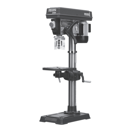
 DP58P Heavy Duty Pedestal Drill with 50” Column & 5/8” Chuck DP58B Heavy Duty Bench Drill with 30” Column & 5/8” Chuck Version 3.1 April 2014 To register this product please visit www.recordpower.info It is important to register your product as soon as possible in order to receive efficient after sales support and be entitled to the full 5 year guarantee.
Contents Explanation of Symbols Operation General Health & Safety Guidance Adjustments & Maintenance Record Power Guarantee 10 Electrical Connection & Wiring Diagram 11 Dust Extraction Specifications Contents of the Package 12 Troubleshooting 13 Parts Lists & Diagrams Getting to Know Your Drilling Machine...
Page 3
2. General Health & Safety Guidance cont. in which the machine is to be used is capable of supporting • Keep the work area well lit and ensure that there is artificial lighting the machine. available when there is insufficient natural light to effectively light the work area.
Page 4
2. General Health & Safety Guidance cont. affected if attempts to make the machine perform beyond its limits 27. Maintain your machine with care are made. • This manual gives clear instructions on installation, set up and operation of the machine and also details any routine and preventative 21.
Guarantee should be made directly to Record Power or its Authorised Distributor Record Power guarantees that for a period of 5 years from the date (for details of the Authorised Distributor in your country please see of purchase the components of qualifying Products (see clauses 1.2.1 your Product manual or check www.recordpower.info for details).
Sound Pressure Level: <83dB (A) Sound Pressure Level: <83dB (A) 5. Contents of the Package A Head Drift key B Column, table support and rack (DP58P) K Table support locking handle C Column, table support and rack (DP58B) Table crank handle D Table...
6. Getting To Know Your Drilling Machine DP58P shown. Belt guard On / off switch Belt tension lock handle Depth scale Belt tension lock cam handle Depth scale indicator Depth scale Feed handle Belt tension Lock handle Column collar Chuck...
7. Assembly Caution: Many of the items are very heavy. We recommend that assistance is sought before trying to lift the larger components. The column, column support and rack are supplied preassembled. To Fig. 7.1 secure to the base, align the four holes in the support casting with the corresponding holes in the base and secure using four M10 x 20 mm hex head screws (Fig.
Page 9
7. Assembly - Cont. Attach the head assembly of the drill to the top of the column and secure Fig. 7.5 using both the M10 x 12 mm blind set screws which are pre-installed to the collar of the head assembly (Fig. 7.5). Before placing the head assembly onto the column, ensure that the blind set screws do not protrude into the inside of the head assembly.
7. Assembly - Cont. The chuck can now be fitted to the arbor. Before fitting the chuck, both Fig. 7.9 the taper of the arbor and the corresponding taper in the rear of the chuck should be thoroughly cleaned to remove any foreign bodies that may Spindle prevent the chuck from seating correctly.
Page 11
8. Operation - cont. Fig. 8.2 Using the Base as a Work Table If the size of the work piece is too large to be accommodated using the work table, it can be swung away from the chuck so that the base can be used to support the work piece (Fig.
Page 12
8. Operation - cont. Using the Depth Stop Fig. 8.6 Depth scale lock The machine features a depth stop on the right hand side of the head assembly (Fig. 8.6). To set the machine to control the depth of the chuck movement, firstly ensure the chuck spindle is fully retracted by turning the feed handle clockwise as far as it will go.
9. Adjustments & Maintenance Checking the Belt Tension Before attempting to use the machine, check that the correct speed is Fig. 9.1 selected in relation to the size and type of drill bit and type of material Locking screw being machined. It is important to apply the correct level of tension. Over- tensioning the belt will apply excessive load to the motor and spindle bearings and may cause damage to the machine.
Page 14
9. Adjustments & Maintenance - cont. Using Large Drill Bits Fig. 9.5 The machine will accept any drill bits with a number 2 morse taper, providing Drift key the chuck and arbor are removed first. To remove the chuck and arbor, turn the feed handle anti-clockwise to expose the hole in the spindle sleeve then align this with the hole in the spindle and place the drift key through both holes so it is positioned above the arbor (Fig.
Page 15
9. Adjustments & Maintenance - cont. Replacing the Headstock Spindle Return Spring Fig. 9.9 Notch The headstock spindle return spring is located on the opposite side of the headstock to the rise and fall handle. It is pre-tensioned at the factory to the correct tension and should need no adjustment through its life.
10. Electrical Connection & Wiring Diagram Machines supplied for use in the UK are fitted with a 3 pin plug conforming machine. If replacing the original fuse, always fit a fuse of equivalent rating to BS1363, fitted with a fuse conforming to BS1362 and appropriate to the to the original.
Record Power Extractors be switched off for 20 minutes every hour. 0.5 micron filtration Record Power offer a range of high quality dust extractors, we offer both drum and bag type extractors which filter down 0.5 micron providing protection from harmful fine dusts. All Record Power dust extractors & chip CX2000 Compact Chip Extractor collectors have 100 mm inlets and hoses.
13. Parts Lists & Diagrams 1-1. Screw-hex soc set 1-2. Collar rack 1-3. Gear rack 1-4. Crank 1-6. Table 1-7. Clamp table 1-8. Screw-hex HD M16 x 20 - 35 1-9. Table assembly. w/scale 1-10. Base 1-11. Support column 1-12. Screw-hex HD M10 x 1.5 - 40 1-13.
Page 20
13. Parts Lists & Diagrams - Cont. Spare Parts Diagram 3 Spare Parts List for Diagram 3 3-1. Retaining ring 3-2. Bearing ball 25mm 3-3. Spacer 3-4. Belt “V” M25 3-5. Nut pulley 3-6. Pulley spindle 3-7. Insert spindle 3-8. Guard pulley w/labels 3-9.
Page 21
13. 13. Parts Lists & Diagrams - Cont. Spare Parts Diagram 4 Spare Parts List for Diagram 4 4-1. Motor adjusting knob 4-17. NVR switch 4-36. Cable clamp 4-2. Screw socket set M10 x 1.5-12 4-18. Switch key 4-37. Motor bracket support 4-3.
Centenary House, 11 Midland Way, Barlborough Links, Chesterfield, Derbyshire S43 4XA declares that the machinery described:- Type: Pedestal Drilling Machine & Bench Top Drilling Machine Model No: DP58P & DP58B Serial No ................. Conforms with the following directives:- MACHINERY DIRECTIVE...
Page 25
Woodworking Machinery & Accessories United Kingdom Eire Australia New Zealand Record Power Ltd Record Power Ltd Tools 4 Industry Tools 4 Industry Centenary House, 11 Midland Way Centenary House, 11 Midland Way Po Box 3844 Po Box 276079 Barlborough Links, Chesterfield...
Need help?
Do you have a question about the DP58P and is the answer not in the manual?
Questions and answers