Table of Contents
Advertisement
Quick Links
Original Instructions
PT107 10" x 7" Heavy Duty
Planer Thicknesser
Version 3.2
April 2022
It is important to register your product as soon as possible in order to receive efficient after sales
support and be entitled to the full 5 year guarantee. Your statutory rights are not affected.
Kg
Always wear safety glasses when
using woodworking equipment.
To register this product please visit
www.recordpower.info
Please see back cover for contact details.
Important
i
For your safety read instructions carefully before
assembling or using this product.
Always read the instructions
provided before using
Save this manual for future reference.
woodworking equipment.
Advertisement
Table of Contents

Related Manuals for Record Power PT107


Summary of Contents for Record Power PT107
- Page 1 Original Instructions PT107 10" x 7" Heavy Duty Planer Thicknesser Version 3.2 April 2022 To register this product please visit www.recordpower.info It is important to register your product as soon as possible in order to receive efficient after sales support and be entitled to the full 5 year guarantee. Your statutory rights are not affected.
-
Page 2: Table Of Contents
Contents Explanation of Symbols General Health & Safety Guidance Additional Health & Safety Guidance for Planer Thicknessers Record Power Guarantee Specifications Contents of the Package Getting to Know Your Planer Thicknesser Assembly Assembly of the Optional Wheel Kit 10 Assembly of the Optional 49000 Thicknessing Table Extension 11 Operation 12 Adjustments &... -
Page 3: Explanation Of Symbols
1. Explanation of Symbols THE SYMBOLS AND THEIR MEANINGS SHOWN BELOW MAY BE USED THROUGHOUT THIS MANUAL. PLEASE ENSURE THAT YOU TAKE THE APPROPRIATE ACTION WHEREVER THE WARNINGS ARE USED. Mandatory Instructions Read and fully understand the instruction manual before attempting to use the machine. Indicates an instruction that requires particular attention Wear protective eyewear Use respiratory protective equipment... -
Page 4: General Health & Safety Guidance
2. General Health & Safety Guidance Ensure that you carefully read and fully understand the are of adequate specification. instructions in this manual before assembly, installation and use 6. The machine should be level and stable at all times of this product. Keep these instructions in a safe place for future •... - Page 5 2. General Health & Safety Guidance cont. complete stop. • Do not use another person as a substitute for a table extension, or as additional support for a work piece that is longer or wider than the basic • If the work area is to be left unattended, all machinery should be table, or to help feed, support, or pull the work piece.
- Page 6 2. General Health & Safety Guidance cont. of parts and any other conditions that may affect the operation of the warranty. the machine. 32. Have your machine repaired by a qualified person • A guard or other part that is damaged should be properly repaired •...
-
Page 7: Additional Health & Safety Guidance For Planer Thicknessers
3. Additional Health & Safety Guidance for Planer Thicknessers WARNING: FOR YOUR OWN SAFETY, DO NOT ATTEMPT TO • Keep your face and body to one side, out of line with a possible OPERATE YOUR PLANER THICKNESSER UNTIL IT IS COMPLETELY kick back. -
Page 8: Record Power Guarantee
Guarantee should be made directly to Record Power or its Authorised Distributor Record Power guarantees that for a period of 5 years from the date (for details of the Authorised Distributor in your country please see of purchase the components of qualifying Products (see clauses 1.2.1 your Product manual or check www.recordpower.info for details). -
Page 9: Specifications
Maximum thicknesser depth of cut: 2 mm Full load current: 9.7 A Maximum thicknessing height: 190 mm 6. Contents of the Package PT107 Planer Thicknesser Spindle cover screws x 4 Fence bracket 10 M5 hex head socket bolts x 2 Bridge guard bracket 11 Spindle cover... -
Page 10: Getting To Know Your Planer Thicknesser
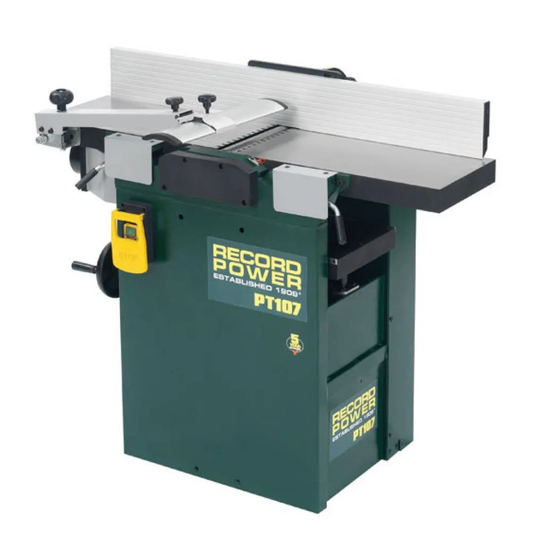
7. Getting to Know Your Planer Thicknesser 1 Fence 8 Dust extraction hood 2 Outfeed table 9 Thicknesser table lock lever 10 Thicknessing table hand wheel 3 Infeed table 4 Table lock 11 Power switch 5 Bridge guard 12 Thicknesser table 6 Bridge guard bracket 13 Thicknesser feed clutch 7 Bridge guard adjustment knobs... -
Page 11: Assembly
Unloading can be performed using a forklift, pallet jack or crane. Use of the PT107/W Jockey Style Wheel Kit is recommended for transport of the machine, Fig. 8.2. Warning: Some metal parts may have sharp edges on them. - Page 12 8. Assembly Fitting the Bridge Guard & Bracket Fig 8.3 Nylon locking nut The bridge guard bracket is supplied with an M10 x 100 mm securing bolt, spacer plate and nylon locking nut already fitted, Fig. 8.3. Remove the nut Securing and attach the bracket to the outfeed table by screwing the bolt into the bolt...
- Page 13 8. Assembly Slide the fence bracket into the carrier as shown in Fig. 8.8. The bracket can Fig 8.8 be locked in position using the locking handle of the carrier. Ensure that the plate attached to the underside of the locking handle mount is positioned beneath the locking handle as shown in Fig.
- Page 14 8. Assembly Once the whole fence assembly is installed, check that the fence is square Fig 8.13 to the table. If not, adjust the position of the fence carrier until alignment is achieved. See Fig. 8.13. Attach the switch cover to the switch box on the front of the machine as shown in Fig.
-
Page 15: Assembly Of The Optional Wheel Kit
9. Assembly of the Optional Wheel Kit Fig. 9.1 Contents of the Package Fig. 9.2 See Fig. 9.1. PT107 1 Lifting bracket Planer 2 Wheel assemblies, hex head nuts and bolts x 2 Thicknesser 3 Hex head nuts and bolts x 2... - Page 16 9. Assembly of the Optional Wheel Kit When the wheel kit is not in use, the wheels fitted to the main body of the Fig. 9.4 machine can be raised by unscrewing the adjusting screw, Fig. 9.4, so that they are clear of the floor. The wheels must be lowered again before using the wheel kit.
-
Page 17: Assembly Of The Optional 49000 Thicknessing Table Extension
Firstly, fix the thicknessing extension table onto the edge of main Flat washer thicknessing table of the PT107, using the 2 M8 hex bolts, 2 M8 hex head socket screws and 2 flat washers supplied, as shown in Fig 10.1, do not fully tighten. - Page 18 10. Assembly of the Optional 49000 Thicknessing Table Extension From the centre point of the two markings previously made, measure 150 Fig 10.5 mm into the table and mark a third line, Fig 10.5. As done previously, measure 16 mm down from the top of the table along the line previously made and mark a fourth line, Fig 10.4.
- Page 19 10. Assembly of the Optional 49000 Thicknessing Table Extension Thread the M8 hex head socket screw along with the first M8 washer Fig 10.9 through the drilled hole as shown. On the opposing side of the table, add the second M8 washer, followed by the M8 nut and repeat this process, Fig 10.9.
- Page 20 10. Assembly of the Optional 49000 Thicknessing Table Extension 49000 Thicknessing Table Extension Drilling Template Template not to scale...
- Page 21 10. Assembly of the Optional 49000 Thicknessing Table Extension Parts List No. Description Quantity Flat washer M8 hex head socket screws M8 hex bolt M10 hex nut Shaft Flat washer (large) Bearing 6001 Table extension roller Table extension M8 hex nut...
-
Page 22: Operation
11. Operation Working techniques Permitted working techniques. Fig 11.1 All uses deviating from those described below are considered improper uses and are therefore not permitted. • Planing the wide side of a workpiece. • Planing the narrow side of a workpiece. •... - Page 23 11. Operation Positioning the Bridge Guard Fig 11.4 Bridge guard Place the timber on the tables and position the bridge guard to be as close Height as possible to the timber without touching it, Fig 11.4. To set the height of adjustment the bridge guard use the height adjustment knob on the bracket, Fig 11.4.
- Page 24 11. Operation Surface Planing Fig 11.9 Caution: Minimise positioning hands above the cutter block. It is not necessary to exert feeding pressure directly over the cutter block. When surface planing, always feed the workpiece at a slow and consistent rate. Feeding the workpiece too quickly will reduce the quality of finish of the planed surface.
- Page 25 11. Operation Fig 11.14 Edge planing When edge planing small stock as shown in Fig. 11.15 the bridge guard Fig 11.15 should be positioned above the work piece to guard as much of the cutter block as possible. When edge planing larger or tall pieces the bridge guard should be positioned against the table as shown in Fig.
- Page 26 11. Operation Fig 11.18 When bevelling, set the bridge guard as shown in Fig 11.18 and when tapering as shown in Fig. 11.19. Due to the nature of the cuts to be made, 10 mm 10 mm the guard cannot be placed as close to the timber and cutter block as when surface planing.
- Page 27 11. Operation Be sure the outfeed table is fully raised and tilted, Fig. 11.23. Fig 11.23 Now raise the infeed table in the same manner. Finally, raise the extraction hood to cover the cutter block, Fig 11.23. To return the machine to planing mode follow the above instructions in reverse order.
- Page 28 11. Operation Using a Planer Thicknesser to Achieve 90º to All Adjacent Fig 11.27 Sides of the Timber The most common use of a planer thicknesser is to plane timbers to accurate sizes and with all adjacent sides at 90º to one another. Using the methods already described in this manual and following the process below, any number of pieces can be planed and dimensioned to exact sizes.
-
Page 29: Adjustments & Maintenance
12. Adjustments & Maintenance Outfeed Table Adjustment Fig 12.1 Please note: The height of outfeed table is factory set. It should only require adjustment in cases where other normal adjustments to the planer knives have not rectified any alignment issues. Please note: Before carrying out any of the adjustments below, Fig 12.2 ensure that the machine is switched off and that the power cord... - Page 30 12. Adjustments & Maintenance Release the infeed table lock, Fig. 12.6, and adjust the table until it is at Fig 12.6 the same height as the outfeed table, Fig. 12.5. Planing depth Lock the infeed table in place. of cut scale Set the pointer as shown in Fig.
- Page 31 12. Adjustments & Maintenance Aligning the In Feed Table with the Cutter Block Fig 12.11 Once the out feed table is aligned correctly, use a straight edge as shown in Straight edge Fig. 12.11 to align the in feed table along its full width to be flush with the out feed table.
- Page 32 Blade setting jig Outer pads To make setting the blades an easier and faster operation, Record Power offer the RPPSJ Planer Blade Setting Jig. Please see online for full details. Check the height of the Blade Blade Screw The blades should be periodically checked for sharpness and position.
- Page 33 Turn them each 1/8 of a turn at a time and stop when resistance Fig 12.19 is felt. In the highly unlikely event that the other bearing needs adjustment, please contact Record Power customer services in your area. Drive Pulleys...
- Page 34 12. Adjustments & Maintenance Cleaning Caution: Before carrying out any adjustments or maintenance Fig 12.22 ensure that the machine is isolated and disconnected from the electricity supply. Chain To avoid a build-up of wood dust, regularly clean the thicknesser drive gear using a brush, Fig.
- Page 35 12. Adjustments & Maintenance Cutter Block & Blades Fig 12.27 CAUTION! This procedure involves close contact with the planer blades. Ensure that protective gloves are worn at all times to prevent injury to hands. Clean the blades, blade holders and cutter block to remove any traces of resin, waste and debris as often as necessary.
-
Page 36: Dust Extraction
90 litre capacity, 1 kW twin or triple motor, 0.5 micron filtration. Includes hose. Record Power Dust Extraction Machines Below is a summary of the Record Power range. Please visit your local stockist CGV486 CamVac Series Heavy Duty Extractor or go online for full details. -
Page 37: Electrical Connection & Wiring Diagram
14. Electrical Connection & Wiring Diagram Machines supplied for use in the UK are fitted with a 3 pin plug conforming machine. If replacing the original fuse, always fit a fuse of equivalent rating to BS1363, fitted with a fuse conforming to BS1362 and appropriate to the to the original. -
Page 38: Troubleshooting
15. Troubleshooting Problem Cause Solution Motor is slow or weak. 1. Low voltage supply. 1. Request a voltage check from local power company. 2. Circuit is overloaded with appliances, lights, or 2. Do not use other appliances or electrically other electrically powered equipment. powered equipment on the same circuit when using this machine. -
Page 39: Parts Lists & Diagrams
16. Parts Lists & Diagrams DESCRIPTION QUANTITY DESCRIPTION QUANTITY Main frame Inner shield Shaft seat, thicknessing table Cross sunk head screw M5 x 6 mm Seat, lock lever Scale, thicknessing height Oil seal Pan head screw M5 x 6 mm Seat, bearing Gear cover Hex lock nut... - Page 40 16. Parts Lists & Diagrams - cont. DESCRIPTION QUANTITY DESCRIPTION QUANTITY Outfeed table, planer Washer 8 mm Table lock seat Hex screw M8 x 30 mm Table swing seat Roll pin D6 x 20 mm Eccentric seat Roll pin D6 x 30 mm Fork Circle ring 12 mm Table lock...
- Page 41 16. Parts Lists & Diagrams - cont. DESCRIPTION QUANTITY DESCRIPTION QUANTITY Feed table, planer Hex screw M8 x 25 mm Table lock seat Roll pin D6 x 30 mm Table lock Roll pin D6 x 20 mm Fork Hex head screw M6 x 12 mm Table swing seat Hex nut M16 Table swing shaft...
- Page 42 16. Parts Lists & Diagrams - cont. DESCRIPTION QUANTITY DESCRIPTION QUANTITY Thicknessing table Hex head screw M6 x 60 mm Raise guide rail Set screw M8 x 12 mm Special guide Oil seal Height indicator Hex screw M8 x 16 mm Edge plate Hex screw M8 x 35 mm Fixed guide rail...
- Page 43 16. Parts Lists & Diagrams - cont. DESCRIPTION QUANTITY DESCRIPTION QUANTITY Cutter block Hex head screw M6 x 60 mm Blade holder Set screw M8 x 12 mm Hex head screw M6 x 12 mm Oil seal Blade Hex screw M8 x 16 mm Spacer Hex screw M8 x 35 mm Bearing cover...
- Page 44 16. Parts Lists & Diagrams - cont. DESCRIPTION QUANTITY DESCRIPTION QUANTITY Sprocket A Spring Flange Handle, friction lever Pan head screw M5 x 8 mm Tension plate Set screw M6 x 6 mm Tension rod Shaft pulley Spring Friction wheel Washer 10mm Sprocket B Bearing 6303...
- Page 45 16. Parts Lists & Diagrams - cont. DESCRIPTION QUANTITY Spacer End cap (right) Screw Screw Pointer Fence extrusion Fence block End cap (Left) Hex bolt M6 Fence locating strip Hex bolt M6 Fence bracket Aluminium fence seat Ratchet handle M8 Fence plate Washer M8 Hex bolts...
- Page 46 16. Parts Lists & Diagrams - cont. DESCRIPTION QUANTITY DESCRIPTION QUANTITY Bridge guard arm Flat washer 8 mm Swivel base, guard Spring Rod, spring Star-type screw M6 x 35 mm Joint, bridge guard Star-type screw M8 x 35 mm Insert, guard Star-type nut Bolt guide Cap nut M8...
- Page 47 16. Parts Lists & Diagrams - cont. DESCRIPTION Washer 16 mm Castor Roll pin 4 x 30 mm Bracket castor Hex screw M12 x 50 mm Bracket castor Washer 10 mm Hex screw M12 x 80 mm Washer 12 mm Bushing bracket Support, pull rod Hex screw M10 x 55 mm...
- Page 48 Andrew Greensted Managing Director Technical file held by Andrew Greensted, Record Power Ltd, Centenary House, 11 Midland Way, Barlborough Links, Chesterfield, Derbyshire, S43 4XA, United Kingdom Record Power B.V., Verlengde Poolseweg 16, 4818 CL BREDA, Netherlands, Tel: +31 76 52 44 766...
- Page 52 Woodworking Machinery and Accessories Record Power Ltd, Centenary House, 11 Midland Way, Barlborough Links, Chesterfield, Derbyshire S43 4XA Tel: +44 (0) 1246 571 020 Fax: +44 (0) 1246 571 030 www.recordpower.co.uk To register a product and find your local stockist visit recordpower.info...
Need help?
Do you have a question about the PT107 and is the answer not in the manual?
Questions and answers