Table of Contents
Advertisement
Original Instruction Manual
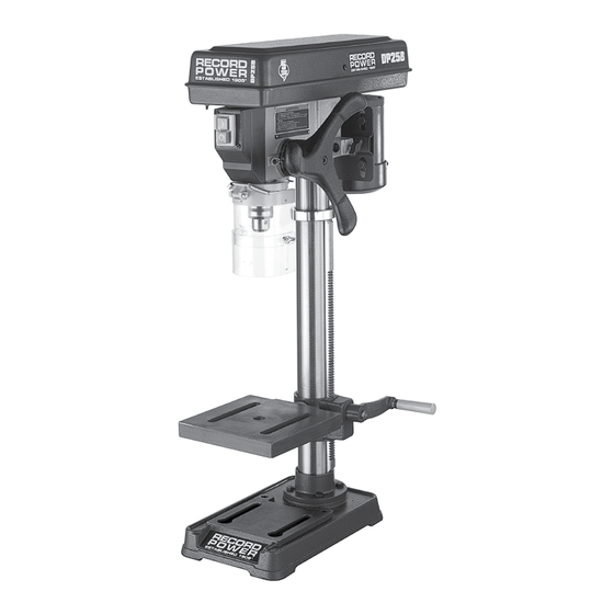
DP25B
Bench Top Drill Press
Version 3.0
January 2014
It is important to register your product as soon as possible in order to receive efficient after sales
support and be entitled to the full 5 year guarantee. Your statutory rights are not affected.
Kg
Always wear safety glasses when
using woodworking equipment.
To register this product please visit
www.recordpower.info
Please see back cover for contact details.
i
Always read the instructions
provided before using
woodworking equipment.
Kg
Important
For your safety read instructions carefully
before assembling or using this product.
Save this manual for future reference.
Advertisement
Table of Contents

Subscribe to Our Youtube Channel
Related Manuals for Record Power DP25B


Summary of Contents for Record Power DP25B
- Page 1 Original Instruction Manual DP25B Bench Top Drill Press Version 3.0 January 2014 To register this product please visit www.recordpower.info It is important to register your product as soon as possible in order to receive efficient after sales support and be entitled to the full 5 year guarantee. Your statutory rights are not affected.
-
Page 2: Table Of Contents
Contents Explanation of Symbols General Health & Safety Guidance Record Power Guarantee Specifications Unpacking & Checking Contents Getting to Know Your Machine Assembly Maintenance & Operation Electrical Connection & Wiring Diagram 10. Troubleshooting 11. Parts Lists & Diagrams EU Declaration Of Conformity... -
Page 3: Explanation Of Symbols
1. Explanation of Symbols THE SYMBOLS AND THEIR MEANINGS SHOWN BELOW MAY BE USED THROUGHOUT THIS MANUAL. PLEASE ENSURE THAT YOU TAKE THE APPROPRIATE ACTION WHEREVER THE WARNINGS ARE USED. Mandatory Instructions Warning Read and fully understand the instruction manual Indicates a risk of severe personal injury or before attempting to use the machine. - Page 4 2. General Health & Safety Guidance cont. the machine to a more suitable position or use packing shims between the lighting, power outlets, or circuits. feet and the floor surface to ensure the machine is stable. • The machine must be connected to an earthed power supply. 7.
- Page 5 2. General Health & Safety Guidance cont. 29. Disconnect the machine from the power supply doubt seek further advice from the manufacturer. • When not in use, before servicing, changing blades etc. always disconnect the 25. Connect dust extraction equipment machine from the power supply.
-
Page 6: Record Power Guarantee
Guarantee claim. Record Power guarantees that for a period of 5 years from the date of Please note that it is essential that the letter of claim reaches Record purchase the components of qualifying Products (see clauses 1.2.1 to Power or its Authorised Distributor on the last day of this Guarantee at 1.2.9) will be free from defects caused by faulty construction... -
Page 7: Specifications
4. Specifications Throat Depth: 127 mm Depth of Feed: 60 mm Chuck to Table: 235 mm Chuck to Base: 355 mm Speeds: 500, 890, 1400, 1900 & 2500 rpm Motor: 1/3 hp Chuck: 2 Morse Taper / 13 mm Weight: 27 kg Size: H850 x W210 x D380 mm... -
Page 8: Getting To Know Your Machine
6. Getting to Know Your Machine Headstock Motor On/Off Switch Depth Stop Hand Wheel Chuck Guard Column Locking Handle Crank Handle Table Base... -
Page 9: Assembly
7. Assembly 1. The column and support casting are supplied pre-assembled. Align the four holes in the support casting Fig. 7.1 with the corresponding holes in the base casting and secure using four M8 x 20mm hex. head 7.03 screws item N. from parts list (Fig. 7.1). 2. - Page 10 7. Assembly cont. 6. Fit the crank handle (L) to the worm gear on the table support. Secure using the M6 x 8mm socket Fig. 7.6 head screw against the flat area of the shaft, (Fig. 7.6). 7. Attach headstock to the top of the column and secure using two M8 x 8mm socket head screws which are Fig.
-
Page 11: Maintenance & Operation
8. Maintenance & Operation Checking Belt Tension and Changing Speed Settings Before attempting to use the machine, check that the correct speed is selected in relation to the size and type of drill bit and type of material being machined. It is important to apply the correct level of tension, as over tensioning the belt will apply excessive load to the motor and spindle bearings and may cause damage to the machine. - Page 12 8. Maintenance & Operation Depth Stop Adjustment Move the drill/cutter to be directly above the workpiece, zero the scale then move the scale to the required depth to be cut and lock in position with the In the event of a blockage or if the machine stalls: depth screw lock, Fig 8.4.
-
Page 13: Electrical Connection & Wiring Diagram
9. Electrical Connection & Wiring Diagram Machines supplied for use in the UK are fitted with a 3 pin plug conforming machine. If replacing the original fuse, always fit a fuse of equivalent rating to BS1363, fitted with a fuse conforming to BS1362 and appropriate to the to the original. -
Page 14: Troubleshooting
10. Troubleshooting Problem Cause Remedy Noisy operation 1. Incorrect belt tension 1. Adjust tension 2. Dry spindle 2. Lubricate spindle 3. Loose spindle pulley 3. Check tightness of retaining nut on pulley and tighten if necessary 4. Loose motor pulley 4. -
Page 15: Parts Lists & Diagrams
11. Parts Lists & Diagrams Description Securing screw Screw-Pan Head M5 x 0.8-12 Motor Pulley Screw - Hex Socket Set M6 x 1.0 - 10 Pulley Assembly Cover *Ball Bearing 12mm x2 Spindle Shaft Chuck Chuck Key Quill Tube Quill Gasket Circlip Screw - Washer Head M6 x 1.0 - 12 Rubber Grommit x2... - Page 16 11. Parts Lists & Diagrams - Cont. Description Description Head with Pointer & Trim *Wire Connector Motor *Lockwasher - Extension 5mm *Nut - Hex M8 Screw - Pan Head M5 x 0.8-12 *Washer M8 x 16 x 1.6 Screw - Pan Head M5 x 0.8-12 NVR Switch Power Cord *Nut - Hex M10...
- Page 17 11. Parts Lists & Diagrams - Cont. Description Table support casting with scale Locking Handle Main column Base Hex head screw M8 x 1.25-20 x4 Hex head screw 1/2 - 12 x 7/8 Table...
-
Page 18: Eu Declaration Of Conformity
Cert No: EU / DPB / 1 RECORD POWER LIMITED, Centenary House, 11 Midland Way, Barlborough Links Chesterfield, Derbyshire S43 4XA declares that the machinery described:- Type: Drill Press Model No: DP25B Serial No ................. Conforms with the following directives:- MACHINERY DIRECTIVE 2006/42/EC LOW VOLTAGE DIRECTIVE... - Page 20 Woodworking Machinery & Accessories United Kingdom Eire Australia New Zealand Record Power Ltd Record Power Ltd Tools 4 Industry Tools 4 Industry Centenary House, 11 Midland Way Centenary House, 11 Midland Way Po Box 3844 Po Box 276079 Barlborough Links, Chesterfield...
Need help?
Do you have a question about the DP25B and is the answer not in the manual?
Questions and answers