Table of Contents

Related Manuals for COHU 3610 SERIES


Summary of Contents for COHU 3610 SERIES
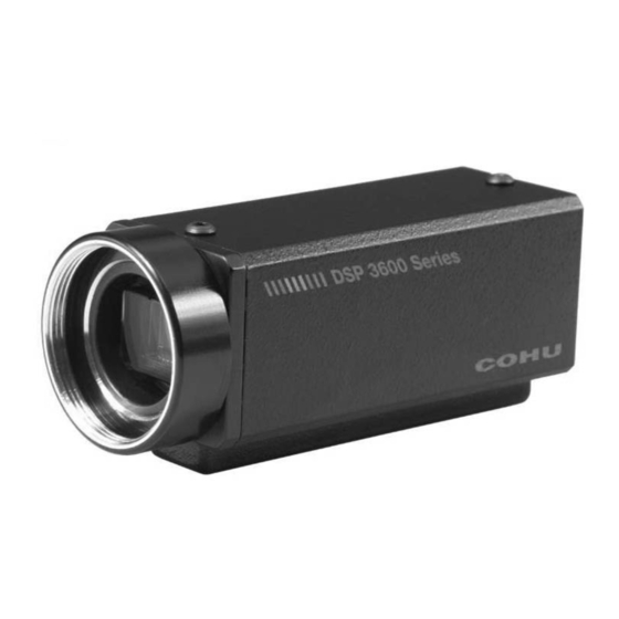
- Page 1 3610 SERIES DSP COLOR CAMERA TECHNICAL REFERENCE MANUAL RS-232C SERIAL CONTROL F C C Figure 1. Machine Vision Color Camera June 22, 2012 Technical Manual 6X-1042D www.cohu-cameras.com www.cohu-cameras.com/content/contactus info@cohu.com...
-
Page 2: Table Of Contents
CAUTION: Changes or modifications to this device not eration is subject to the following two conditions: (1) this expressly approved by Cohu Electronics could void the device may not cause harmful interference, and (2) this user’s authority to operate the device. -
Page 3: General Description
4. This diagram shows the various 1.1 Electrical Characteristics basic configurations of the Camera. The 3610 Series provides a small, light- Dimensions for the Camera are shown in fig- weight, highly sensitive machine vision CCD ure 5. Figure 6 is a detailed dimensional illustra-... - Page 4 3610 CAMERA TECHNICAL REFERENCE Table 1. Specifications ELECTRICAL Interline transfer color CCD operating in field mode 1/2 inch (6.45 × 4.84 mm) Format 1/3 inch (4.44 x 3.33 mm) 1/4 inch (3.33 × 2.5 mm) Pixels 768 × 494 NTSC; 752 × 582 PAL 1/2 inch: 8.40 (H) ×...
- Page 5 TECHNICAL REFERENCE 3610 CAMERA Table 1. Specifications (continued) MECHANICAL Dimensions 1 x 1 x 3 inch, less lens (see figure 5) Weight 2.9 oz (82 g), less lens Two 1/4-20 screws (accepts 0.200 deep screw) top or bottom mounting block, Camera Mount or direct to top or bottom of camera body with two 2-56 inch screws, or via CS mount direct to microscope or similar device...
-
Page 6: Installation
3. Locking setscrew for adapter (4-40 x 5/32) 4. Graphical User Interface (GUI) available either with the Camera on disk or downloaded from: www.cohu-cameras.com/tech/tech.htm The following items are provided if the option- al accessory kit has been ordered (table 4): 1. -
Page 7: Equipment Required But Not Supplied
TECHNICAL REFERENCE 3610 CAMERA a. 5 V dc, 500 mA power supply (Cohu type 8470-5) or b. 12 V dc, 350 mA power supply (Cohu type 8368-4) Note that special-order Cameras and Camer- as modified for special purposes may be shipped with other items. -
Page 8: Power Requirements
3610 CAMERA TECHNICAL REFERENCE 361 x — x x x x — ×××× LENS SERIES 0000 None SYNC (Manual iris, CAMERA 1 Internal crystal auto iris & ACCESORIES 2 H&V drive dc iris lenses available) IRIS 0 None 1 Test cable POWER 0 Manual Iris &... - Page 9 TECHNICAL REFERENCE 3610 CAMERA Optical path includes 0.031 (0.8) thick BK-7 flat glass and 0.213 (5.4) thick multilayer quartz optical low-pass filter. Actual image plane is 0.81 (2.1) behind effective image plane. Locking Setscrew Effective Image Plane (Nominal Position) 1.00 1.125 (25.40) (28.57)
-
Page 10: Sync Requirements
3610 CAMERA TECHNICAL REFERENCE 2.8 CS- and C-mount Adapters 2.6 Sync Requirements Lenses must be suitable for use with size of A standard camera is available in two differ- the sensor installed in the Camera (1/4-, 1/3-, or ent versions related to sync: 1/2-inch). - Page 11 TECHNICAL REFERENCE 3610 CAMERA Table 2. Capabilities AUTOMATIC OPERATION Standard Feature Camera can be set up for unattended operation with no operator input SERIAL REMOTE CONTROL FUNCTIONS Modifies high frequency response in camera circuits to enhance black-white transitions in the scenes. Has the effect of making scenes look “sharper.” Can Programmable Aperture Correction be implemented for horizontal alone, vertical alone, or for both horizontal and vertical simultaneously...
-
Page 12: Operation
3610 CAMERA TECHNICAL REFERENCE Table 2. Capabilities (continued) OTHER CAPABILITIES All versions of the Camera can be used with a manual iris lens. A 12 V dc version Auto iris, dc iris, manual iris lens selec- of the Camera can also be optioned for use with an auto iris lens or a dc iris lens tions —... -
Page 13: Dsp3600 Gui Home Screen
TECHNICAL REFERENCE 3610 CAMERA Table 3. Items Supplied Table 4. Optional Accessory Kit ITEMS SUPPLIED KIT 8478-3 (12 Volt Cameras) ITEM DESCRIPTION PART NUMBER ITEM DESCRIPTION PART NUMBER CS-mount, 0.335 wide 8359208-001 Wrench, hex key, 1/16 inch 9710010-009 Set Screw, nylon tipped, 2010258-005 5 mm extender stainless, 4-40 x 5/32... -
Page 14: Back Light Compensation (Blc)
H & V drive inputs at pins 6 & 7 are an option Table 6. Mating Rear Panel Connector Plug VIEWED FROM REAR PANEL CONNECTOR MATING CABLE PLUG OUTSIDE OF Cohu 1310397-312 Cohu 1310398-212 REAR PANEL Hirose HR10A-10R-12PC Hirose HR10A-10P-12S SAME AS WIRING... - Page 15 TECHNICAL REFERENCE 3610 CAMERA 5 V - Manual Iris Lenses - Freeze Frame - H & V Drive Composite Video 6 FOOT CABLE LENGTH RS-232C Serial 5 V dc Freeze Frame Note: Pin numbering varies from mfg. to mfg. with this type plug. Always wire to the follow- ing physical layout diagram when wiring any Y-C plug.
- Page 16 3610 CAMERA TECHNICAL REFERENCE 12 V - No Freeze Frame - with Auto, DC, or Manual Iris Lens 6 FOOT CABLE LENGTH (Lens leads 4 inch) 4-inch length NOTE: Pin numbering varies from mfg. to mfg. with this type plug. Always wire to the following physical layout diagram when wiring any Y-C plug.
- Page 17 TECHNICAL REFERENCE 3610 CAMERA Figure 10. Test Cable, CTC-32 (modified for H & V) (12 V dc Freeze Frame Configuration) 6X-1042D...
-
Page 18: Off (Fixed Weighted Average)
3610 CAMERA TECHNICAL REFERENCE POWER SUPPLY 5 V dc 500 mA or COMPUTER OPTIONAL 12 V dc 350 mA MONITOR DEPENDS ON MODEL OF CAMERA SCENE MONITOR Optional connection for 12 V dc Camera COMPOSITE with auto or dc iris lens VIDEO CAMERA 5V dc or 12 V dc... -
Page 19: Eeprom Button
TECHNICAL REFERENCE 3610 CAMERA required to send menu selections to the Camera. This occurs immediately when a menu selection is changed.) 3.1.5 EEPROM Button Clicking the EEPROM button stores the current GUI settings in the Camera memory. This then becomes the Camera default settings until new settings are entered by pressing the EE- PROM button again with different selections. - Page 20 3610 CAMERA TECHNICAL REFERENCE NOTE: The Ext Sync (External Sync) selection should be HDVD (Horizontal Drive Vertical Drive) when a camera has been optioned for H and V drive inputs. Special order cameras having the Comp (Composite) sync input feature should use the Comp selection Figure 13.
- Page 21 Opens new screen for either lens iris setup or aperture conditions Set AE Windows Opens new screen for setting gain control windows size and locations About About Cohu 3600 Opens new window identifying program and version level BLC (Back Light Compensation) Windowed fixed weighting (5 areas)
-
Page 22: Unpacking And Receiving Inspection
3610 CAMERA TECHNICAL REFERENCE Table 7 (continued) FUNCTION AREA NAME EFFECT Effects (continued) Removes any digital zoom in effect Digitally zooms in Digitally zooms out Tilt up button Moves up in the scene Zoom Control Tilt down button Moves down in the scene Pan right button Moves right in the scene Pan left button... - Page 23 TECHNICAL REFERENCE 3610 CAMERA Table 8. Lens Dialog Screen FUNCTION AREA NAME EFFECT Lens Level Setting range Adjustment range from 109 to 149 (DC IRIS only) DC Servo For dc iris lens Sets the dc iris drive stage for the lens being used Video Servo For auto / video iris lens Sets the auto iris video drive stage for lens used...
- Page 24 3610 CAMERA TECHNICAL REFERENCE Table 9. Set Weight Screen FUNCTION AREA NAME EFFECT Show Windows Click 0 to place this window into scene video Click 2 to place this window into scene video Physical locations of click buttons corresponds to Click 4 to place this window into scene video corresponding window areas shown above...
-
Page 25: Preparation For Shipment And Storage
TECHNICAL REFERENCE 3610 CAMERA damage must be made to the carrier. To return the product to the factory for service, please contact the Customer Service Depart- ment for a Return Authorization Number. If a visual inspection shows damage upon receipt of this shipment, it must be noted on the freight bill or express receipt and the notation signed by the car- rier’s agent. - Page 26 3610 CAMERA TECHNICAL REFERENCE Figure 17. Non-linear Y-gamma Characteristics Figure 18. Linear Y-gamma Characteristics 6X-1042D...
-
Page 27: Warranty
TECHNICAL REFERENCE 3610 CAMERA 7.0 WARRANTY Please refer to the Cohu website for product warranty information: http://www.cohu-cameras.com/warranty/WarrantyStatement.pdf. Revision History Revision Date Comments This manual has been revised to comply with 4/28/11 the latest engineering requirements. See ECO 030972 for the list of changes...
Need help?
Do you have a question about the 3610 SERIES and is the answer not in the manual?
Questions and answers