Table of Contents
Advertisement
Quick Links
3950 iVIEW
COHU, INC. ELECTRONICS DIVISION
Installation and Operation Manual
3950 SERIES iVIEW
CAMERA/POSITIONER SYSTEM
Phone: 858-277-6700
FAX:
858-277-0221
Cohu Electronics • 3912 Calle Fortunada • San Diego, CA 92123-1827
6X-1027a
INSTALLATION AND OPERATION
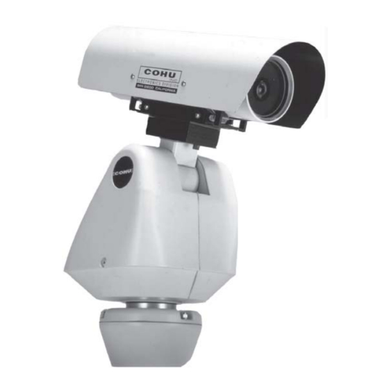
Figure 1. iView
Email: info@cohu.com
WEB: www.cohu-cameras.com
.
August 12, 2005
COHU
Cohu Inc., Electronics Division
1
Advertisement
Table of Contents

Related Manuals for COHU 3950 SERIES iVIEW


Summary of Contents for COHU 3950 SERIES iVIEW
- Page 1 Installation and Operation Manual Figure 1. iView 3950 SERIES iVIEW CAMERA/POSITIONER SYSTEM August 12, 2005 Phone: 858-277-6700 Email: info@cohu.com FAX: WEB: www.cohu-cameras.com 858-277-0221 COHU Cohu Electronics • 3912 Calle Fortunada • San Diego, CA 92123-1827 Cohu Inc., Electronics Division 6X-1027a...
-
Page 2: Table Of Contents
C able C A-297C (RS-422) BNC P lug, P ower Plug, & 232/422 C onverter by Cohu Electronics could void C able C A-297D Model 9300 Local C ontrol Panel to iV iew 3955 the users authority to operate the C able C TC -30, Test/S etup Wiring D iagram equipment. -
Page 3: Specifications
Opto-isolated serial port RS-422 with digital position feedback; Communications RS-232 and RS-485 available Protocol Non-propritary Cohu standard, others optional (see figure 2, protocols) Firmware Stored in flash memory; upgrade via serial port Pan/Tilt 360° continuous pan; +40º to -90º down Preset Speed >100°/second preset, at 0.5°... -
Page 4: General Description
The Cams protocol software is intended for controlling multi-camera/positioner systems when The positioner speeds are variable with maxi- the Cohu MPC Master Control Panel is the central mums of 100° per second in pan mode and 20° per control “intelligence” for the system. All control and second in tilt while sustaining 90 mph winds. -
Page 5: Installation
POWER ( Pedestal, Large Base) LPED CONFIGURATION PROTOCOLS 3 - 230 Vac 1 - Cohu 4 - 24 Vac UNASSIGNED 5 - 115 Vac Protocols of other manufacturers may also be implemented by the camera/positioner Figure 2. Model Number Interpretation lens. -
Page 6: Unpacking And Receiving Inspection
INSTALLATION AND OPERATION 3950 iVIEW in the event that an open unit were available, the 2. Wall Mount (WALL model) following precautions should be followed: This mounting arrangement requires an arm that CAUTION bolts to the wall and an adapter plate between the arm and the bottom of the Positioner. -
Page 7: Typical P Edestal Mount Installation
3950 iVIEW INSTALLATION AND OPERATION Positioner Small Pedestal Baseplate (PEDD) Dimensions Base is permanently attached to the iView Dimensions Large Pedestal Base (LPED) are shown in fig. 4 POSITIONER Positioner with 34-inch “pigtail” and connector CONNECT PLACE INSIDE THROUGH CONDUIT CONTROL EQUIPMENT CONDUIT... -
Page 8: Equipment Supplied
INSTALLATION AND OPERATION 3950 iVIEW Base is permanently attached to the iView Dimensions of Small Pedestal Base (PEDD) are shown in fig. 3 Figure 4. Dimensions, Large Pedestal Base (LPED) 2.3 EQUIPMENT SUPPLIED Farther out from that pattern is a 7.25-inch diam- Depending on the mounting configuration, several eter pattern displaced by 22.720 degrees from the variations of equipment can be supplied. -
Page 9: Equipment Required But Not Supplied
3950 iVIEW INSTALLATION AND OPERATION POSITIONER WALL Route system POSITIONER CABLE cable through (Route through Adapter hole in wall Plate into Arm) into Arm ADAPTER PLATE NOTE: Arm is typically shipped with Adapter Plate attached Use weather-tight gasket between Arm and wall Figure 5. -
Page 10: Typical P Ole Mount Installation
INSTALLATION AND OPERATION 3950 iVIEW Typical Installation of pole mounted Positioner showing cable routng Strain relief must be used on cable to prevent tension on the connectors POSITIONER POLE MOUNT (Strapped to Pole) POSITIONER CABLE (Route through Adapter Plate into Arm) ADAPTER PLATE POLE... -
Page 11: Power Requirements
3950 iVIEW INSTALLATION AND OPERATION 6.00 (15.24) ADAPTER PLATE 0.38 (0.97) 4.75 (12.07) B.C 1/4-20 2.25 (5.72) B.C 18.50 (46.99) 20.00 (50.80) Figure 7. Arm and Apapter Plate Dimensions 2.5 POWER REQUIREMENTS 1. Route the cable pigtail down into the pedestal. Depending on the model, a Positioner requires This cable should be secured by a strain relief either 24 V ac 60 Hz, 115 V ac 60 Hz, or 230 V ac 50... -
Page 12: Wall Mount Installation
INSTALLATION AND OPERATION 3950 iVIEW Figure 8. Pole Mount Bracket Dimensions 2.7 WALL MOUNT INSTALLATION 5. Bolt the Arm to the wall. With a wall-mount installation, a support arm bolts 6. Attach the two connectors to each other and feed to a wall and the iView then bolts to the arm. -
Page 13: Installation And Operation
3950 iVIEW INSTALLATION AND OPERATION iVIEW POSITIONER (115 V ac Version) CA-297D Cable (iView to 9300 Local Control Panel) NOTE: This panel is optional. It is used only when on-site control of an iView is desired for setup and maintanance operations Camera Video Serial... -
Page 14: Cabling Requirements
INSTALLATION AND OPERATION 3950 iVIEW iView 115 VAC RS422 EQUIPMENT CABINET NOTE: THE VIDEO LINE MUST BE TERMINATED FIBER OPTIC WITH 75 OHMS FOR TRANSCEIVER 75 OHM PROPER OPERATION VIDEO IN 75 OHM COAX RS422 DATA TERMINAL STRIP TWISTED PAIR SERIAL DATA WIRES (LUGS ADDED) -
Page 15: Equipment
3950 iVIEW INSTALLATION AND OPERATION Figure 11. Cable CA-297A (RS-422) Stripped Leads Version Always pre-plan all system cabling before starting Figure 12 is the assembly diagram for the cable an installation. Before an iView is bolted in place, the used between an iView and a typical junction box. system cable must be available to attach to the This cable has an ac power plug, BNC video con- pigtail cable at the mounting location. -
Page 16: Required Cable Characteristics
115 or 230 V ac operation. POWER Pin functions for the 24 V ac version of an iView NOTE: For distances exceeding 250 feet, please contact an are not shown in this manual. Applications Engineer at Cohu Electronics. 6X-1027a... -
Page 17: C Able C A-297C (Rs-422) Bnc P Lug, P Ower Plug, & 232/422 C Onverter
3950 iVIEW INSTALLATION AND OPERATION Figure 13. Cable CA-297C (RS-422) BNC Plug, Power Plug, & 232/422-Converter with its mating system cable plug, it is recom- mended that for additional protection against mois- to itself before use. After this material is wrapped ture in severe conditions a sealing wrap be used on around a connector it forms a permanent weather- the two connectors. -
Page 18: Gui Interface
INSTALLATION AND OPERATION 3950 iVIEW Figure 14. Cable CA-297D, Model 9300 Local Control Panel to iView 3955 2.10.1 Win MPC Setup 2.10 GUI INTERFACE When Win MPC (figure 17) is used to set up the Several GUI interfaces are available for use with iView, it must be isolated from all other iViews in the the iView. -
Page 19: C Able C Tc -30, Test/S Etup Wiring D Iagram
3950 iVIEW INSTALLATION AND OPERATION Figure 15. Cable CTC-30, Test/Setup Wiring Diagram This converter converts the RS-232 output of a PC to (Available from Cohu as Part Number 3010100-001) RS-422 for communications with an iView during field setup and testing. sales@bb-elec.com... -
Page 20: Typical W In Mpc Application
INSTALLATION AND OPERATION 3950 iVIEW Table 4. Connector Pin Functions 115 or 230 V ac FUNCTION video signal (75 ohm) video ground data ground (RS-422) (RS-422) (RS-422) (RS-422) not used not used not used not used 115 or 230 V ac line (hot/high) 115 or 230 V ac neutral (low) overall shield Figure 17. -
Page 21: Typical W In Mpc "Home" Screen
3950 iVIEW INSTALLATION AND OPERATION Figure 18. Typical Win MPC “Home” Screen 2.10.3 Setting the iView Address c. Baud Rate to “9600” (Click “Set Baud”) After the initial setup, it is a good idea to allow Win d. Comm Mode “PC to MPC Receiver” MPC to search for the existing iView address: This will verify that communications has been estab- e. -
Page 22: Communications Settings
INSTALLATION AND OPERATION 3950 iVIEW Figure 19. Win MPC Communications Functions Screen Click on the FIND button again to confirm that this Table 5. Communications Settings new address has been accepted. 2.10.4 Checkout Procedure COMMUNICATIONS SETTING FUNCTION After communications has been established with the iView various functions should be tested Port COM 1 (Typical. -
Page 23: Preparation For Shipment And Storage
RS-422 cable. Figure 14 shows a cable for direct connection of a laptop computer having an RS-232 Cohu Electronics serial port to the model 3955 iView pigtail cable. Note 3912 Calle Fortunada that this cable has a 232/422 converter so the 232... - Page 24 Cohu, in no event, whether as a result of breach of contract or warranty, tort (including negligence) or otherwise, shall be liable for any penalties regardless of reason;...
Need help?
Do you have a question about the 3950 SERIES iVIEW and is the answer not in the manual?
Questions and answers