Table of Contents
Advertisement
Advertisement
Table of Contents

Related Manuals for COHU 3920 SERIES


Summary of Contents for COHU 3920 SERIES
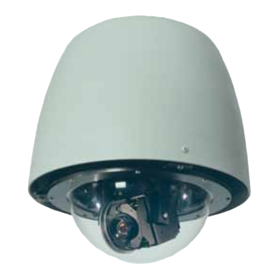
- Page 1 3920 iDOME INSTALLATION AND OPERATION COHU, INC. ELECTRONICS DIVISION Installation and Operation Manual Figure 1. iDome 3920 SERIES iDOME CAMERA/POSITIONER SYSTEM June 21, 2012 Technical Manual 6X-1026E www.cohu-cameras.com www.cohu-cameras.com/content/contactus info@cohu.com 6X-1026E...
-
Page 2: Table Of Contents
INSTALLATION AND OPERATION 3920 iDOME TABLE LIST OF FIGURES OF CONTENTS FIG. TITLE PAGE SECTION TITLE PAGE iDome GENERAL DESCRIPTION Model Number Interpretation Diagram Electrical Characteristics Dimensions, 3920 Mechanical Characteristics Basic Mounting Configurations INSTALLATION Model 8540B Test Stand Installation Introduction Type CTC-29 Cable, Test/ Setup, Wiring Diagram Equipment Supplied Typical RS-232 to RS-422 Converter... -
Page 3: General Description
Operation of this equipment in a residential area is likely to cause this device not expressly approved by harmful interference in which case the user will be required to correct Cohu Electronics could void the user’s the interferecne at his own expense. authority to operate the device. -
Page 4: Mechanical Characteristics
INSTALLATION AND OPERATION 3920 iDOME MODEL NUMBER INTERPRETATION DIAGRAM 392× — × × 0 × — ×××× MOUNT SERIES PEND DSP color/mono 1/4 inch POLE progressive scan dome FEATURES WALL camera with zoom lens Low Pressure Indicator Heaters DOME Variable Speed 360° pan POWER 0 Clear 1 Smoked 4 24 Vac PROTOCOL 5 115 Vac 1 Cohu Protocol... - Page 5 3920 iDOME INSTALLATION AND OPERATION Figure 3. Dimensions, 3920 iDome A single multiconductor cable is routed to the Table 1. Basic Mounting Arrangements iDome location and then passed through the mount- ing pendant to provide for all signal, video, and op- erating power connections.
-
Page 6: Installation Introduction
INSTALLATION AND OPERATION 3920 iDOME 2.1 INSTALLATION INTRODUCTION Always preplan the installation to be sure that all required cabling and address assignments are com- This section is a brief overview of the various pleted. It may also be important to know the orienta- mounting types. - Page 7 3920 iDOME INSTALLATION AND OPERATION 5. Connect a tv monitor to the cable. This set of three legs that increases it from a monitor must be terminated with 75 20-inch height to a 38 inch height. ohms. Monitors typically have a rear 2.
- Page 8 INSTALLATION AND OPERATION 3920 iDOME Figure 6. Type CTC-29 Cable , Test/Setup, Wiring Diagram This converter changes the RS-232 output of a PC to RS-422 for communications with an iDome during field setup and testing. (Also Available from Cohu as P/N 3010100-001) sales@bb-elec.com MAY BE REQUIRED A local PC with Win MPC software typically is used in this ap-...
-
Page 9: Equipment Supplied
3920 iDOME INSTALLATION AND OPERATION Figure 8. Type CTC-33 Cable , 9200 Control Panel Connection, Test/Setup, Wiring Diagram 9. Verify proper operation of all the various 6. Wrap the connector with self sealing functions controllable through the Win waterproofing tape to ensure a long-term MPC menus. -
Page 10: Wall Mount Arm
INSTALLATION AND OPERATION 3920 iDOME Figure 9. Quick Disconnect Assembly WALL Route system cable through hole in wall into Arm 1.5 NPT for dome Use weather-tight gasket quick disconnect between Arm and wall adapter Figure 10. Wall Mount Arm 6X-1026E... -
Page 11: Arm Dimensions
3920 iDOME INSTALLATION AND OPERATION 4.50 UNLESS OTHERWISE NOTED ALL DIMENSIONS IN INCHES O0.375 0.75 (TYP 4 PLACES) O2.0 1.75 17.75 1.75 1.5 NPT Figure 11. Arm Dimensions 2.2.1 PEND (Pendant Mount). See figure 9. directed down behind the pole bracket or, if arrange- ments have been made for this, into the pole. -
Page 12: Equipment Required But Not Supplied
INSTALLATION AND OPERATION 3920 iDOME The web site for Coax-Seal has complete informa- This product is available from a variety of com- tion about this product. mercial supply houses, consumer stores, and in the U.S. Government supply channels as GSA Sched- ule GS-07F-5739R 2.3 EQUIPMENT REQUIRED BUT NOT SUPPLIED... -
Page 13: Power Requirements
3920 iDOME INSTALLATION AND OPERATION 1.5 NPT Nipple Lock Bolt Safety Strap Sunshield (Camera Below) Figure 13. iDome Quick Disconnect Mounting • Fiber optic or other type system intercon- • Connector sealing tape such as Coax Seal nection • Junction box or equipment cabinet for sys- •... -
Page 14: Mast Arm Mount
INSTALLATION AND OPERATION 3920 iDOME Power for 115 and 230 V ac versions of the iDome use the same connector pins (“U” hot/high and “T” low/neutral). But a camera is never capable of being operated from both of these voltages. It will be wired for either 115 V ac or 230 V ac. - Page 15 3920 iDOME INSTALLATION AND OPERATION NOTE: Use of this panel or a similar type panel is optional. They are used only when on-site control of an iDome is desired for setup and maintenance operations 115 V ac iDome operating with CABLE RS-422 data CA295H...
-
Page 16: Wall Mount Installation
INSTALLATION AND OPERATION 3920 iDOME CABLE CA295F EQUIPMENT CABINET NOTE: THE VIDEO LINE MUST BE TERMINATED FIBER OPTIC TRANSCEIVER WITH 75 OHMS FOR PROPER OPERATION 75 OHM VIDEO IN 75 OHM COAX 115 V ac iDome RS422 DATA operating with TERMINAL RS-422 data STRIP... -
Page 17: Pole Mount Installation
3920 iDOME INSTALLATION AND OPERATION 5. Provide for weather tight mounting at the must pass through the wall and into the pole mount bracket. arm. 6. Bolt the Arm to the bracket. 4. Route the system cable out of the wall and into the back of the wall mount arm. - Page 18 INSTALLATION AND OPERATION 3920 iDOME Table 3. Common System Cables Used Basic Characteristic System Side Connections Cable iDome Camera Side Conn. Fig. Model Model (power/data/video) Power Data Video Distance Power Data Video CA-292A 3924 24 Vac RS-232 ntsc 80 feet single 18-pin MS style prepped prepped...
- Page 19 3920 iDOME INSTALLATION AND OPERATION CA292A Figure 19. Cable CA292A 24 V ac NTSC (RS-232) All Prepped Wiring Diagram CA292B Figure 20. Cable CA292B 24 V ac NTSC (RS-232) Prepped/D9/BNC Wiring Diagram 6X-1026E...
- Page 20 INSTALLATION AND OPERATION 3920 iDOME CA293A Figure 21. Cable CA293A 24 V ac NTSC (RS-422)All Prepped Wiring Diagram CA293B Figure 22. Cable CA293B 24 V ac NTSC (RS-422) Prepped/422-232/BNC Wiring Diagram 6X-1026E...
- Page 21 3920 iDOME INSTALLATION AND OPERATION CA293M Figure 23. Cable CA293M, Video BNC, 115 V ac Prepped Power Leads, RJ-45 RS-422 Data 2.10.1 24 V ac RS-422 Cables Figure 23 (CA-293M) is for use with system control panels that have an RJ-45 port providing RS-422 Figure 19 shows cable CA-292A.
- Page 22 INSTALLATION AND OPERATION 3920 iDOME CA295E Figure 24. Cable CA295E 115 V ac (RS-422) All Prepped Wiring Diagram CA295F Figure 25. Cable CA295F 115 V ac (RS-422) Plug/Prepped/BNC Wiring Diagram 6X-1026E...
- Page 23 3920 iDOME INSTALLATION AND OPERATION CA295G Figure 26. Cable CA295G 115 V ac (RS-422) Plug/422-232/BNCWiring Diagram CA295H Figure 27. Cable CA295H 115 V ac (RS-422) Single AMP Connector (iControl use) Wiring Diagram 6X-1026E...
- Page 24 INSTALLATION AND OPERATION 3920 iDOME CA295M Figure 28. Cable CA295M 115 V ac (RS-422) Plug/RJ45/(Mavix)/BNC Wiring Diagram Figure 28 (CA-295M) has a 115 V ac power plug Figures 24 through 28 show cables for RS-422 on the system side, an RJ-45 (Ethernet type) con- communications.
- Page 25 3920 iDOME INSTALLATION AND OPERATION CA296A Figure 29. Cable CA296A 115 V ac (RS-232) All Prepped Wiring Diagram CA296B Figure 30. Cable CA296B 115 V ac (RS-232) Plug/Prepped/BNC Wiring Diagram 6X-1026E...
-
Page 26: Gui Interface
INSTALLATION AND OPERATION 3920 iDOME CA296C Figure 31. Cable CA296C 115 V ac (RS-232) Plug/D9F/BNC Wiring Diagram 2.11.1 Win MPC Setup 2.11 GUI INTERFACE CAUTION As previously mentioned, several GUI interfaces are available for use with this iDome. Do not connect WinMPC to more than one iDome (or other addressable equipment) at a time. - Page 27 3920 iDOME INSTALLATION AND OPERATION 115 AND 230 VAC VERSIONS 24 VAC VERSION hot/line Camera 24 V ac high 115 or 230 V ac neutral Camera 24 V ac low 115 or 230 V ac Ground (Cable Shield) 24 V ac Gnd Response Out + (Tx+) Response Out + (Tx+) Response Out - (Tx-)
- Page 28 INSTALLATION AND OPERATION 3920 iDOME Table 4. iDome Connector Functions Table 5. Communications Settings FUNCTION COMMUNICATIONS SETTING FUNCTION Video Shield (75 ohm ) Port COM 1 (Typical. Verify) 24 V ac high (camera) Baud Rate 9600 24 V ac high (heaters) Var Speed P/T RS-232 Response Out (Tx) Pan/Tilt...
- Page 29 3920 iDOME INSTALLATION AND OPERATION To do this click on the FIND button at upper left of the Cohu WinMPC (home) screen. A pop-up window will appear while WinMPC searches for all allowable camera addresses (0 to 223). The factory default setting is “1.”...
-
Page 30: Local Panel Control
INSTALLATION AND OPERATION 3920 iDOME Figure 35. Typical Win MPC Communications Setup Screen 3.0 OPERATION dress and click on “Set” in the “Set Address” area. Click on the FIND button again to confirm that this Software providing a graphical user interface new address has been accepted. -
Page 31: Local Laptop Pc Control
3920 iDOME INSTALLATION AND OPERATION not accidentally fall. When installing the top (nipple) A portable tv monitor must be connected to this half of this assembly the safety strap is temporarily panel for viewing scenes from the iDome video removed so that it can be threaded into the female output. -
Page 32: Shipping And Static Dis- Charge Considerations
INSTALLATION AND OPERATION 3920 iDOME nitrogen or elect to do so yourself. The Keep all cartons and packing materials. Since iDome uses a standard Schrader valve shipping damage is the carrier’s responsibility, the to repressurize. Use only dry nitrogen carrier will furnish you with an inspection report and for this purpose. - Page 33 3920 iDOME INSTALLATION AND OPERATION Lock Down Bolts (2) 18 Pin Connector (Below) 1.5 NPT Nipple Pressure Relief Valve (5 psig) (Protected by Plastic Tubing) Schrader Valve Safety Strap (Cap Installed) Quick Disconnect Assembly Ventilation Hole Sun Shield (Camera Body Below) Figure 36.
-
Page 34: Schrader Valve
INSTALLATION AND OPERATION 3920 iDOME Use these guidelines to maintain and recharge the camera if it needed. 6.0 Maintenance The system is intended for long-term unattended use and the maintenance requirements are minimal: • clean exterior as needed when the Camera is operated in a harsh environment. •... - Page 35 3920 iDOME INSTALLATION AND OPERATION 6.1.1 Pressurizing Procedure The following items are required for pressurizing: • a tank of dry nitrogen with a regulator • a hose with a strait air chuck to connect to the Schrader valve NOTE: Preferred gas for pressurization is dry nitrogen. Argon is an acceptable substitute. Do not use com- pressed air.
-
Page 36: Specifications
INSTALLATION AND OPERATION 3920 iDOME Table 6. Specifications SYSTEM SPECIFICATIONS CAMERA SPECIFICATIONS PAN/TILT DRIVE 1/4 inch interline transfer Imager color CCD 360° continuous pan range Angular Travel -90° to +5° tilt range Resolution 470 horizontal tv lines 23X lens & EIS Pan Speed (preset) 250°/second 520 horizontal tv lines... -
Page 37: Installation
3920 iDOME INSTALLATION AND OPERATION Table 6. Specifications (continued) VIDEO SPECIFICATIONS ENVIRONMENTAL SPECIFICATIONS VLIW/DSP TI TMS320DM642-600 Protection Rating IP67 & NEMA 4X; MPEG4 ISO/IEC 14496-2 ASP; Ambient Temp. Limits Video Encoding -34 to 74 °C (-27 to 165 °F) RTP/UDP stack Operating: -40 to 85 °C (-40 to 185 °F) Storage:... - Page 38 INSTALLATION AND OPERATION 3920 iDOME WARRANTY Please refer to the Cohu website for product warranty information: http://www.cohu-cameras.com/warranty/WarrantyStatement.pdf Revision History Revision Date Comments This manual has been revised to com- ply with the latest engineering require- Rev C 04/29/2011 ments. See ECO 030972 for the list of changes.
Need help?
Do you have a question about the 3920 SERIES and is the answer not in the manual?
Questions and answers