
Subscribe to Our Youtube Channel
Related Manuals for COHU 3920HD series


Summary of Contents for COHU 3920HD series
- Page 1 Helios Products Series INSTALLATION MANUAL 3920 3920 Dome Positioner System Technical Manual 6X-1097B www.CohuHD.com info@CohuHD.com July 15, 2014...
-
Page 2: Table Of Contents
Table of Contents About this document Additional information and documents related to the Camera Copyright/Intellectual property rights statement FCC compliance Support services Returns Safety instructions 1.0 Introduction 1.1 Product Description 1.2 Equipment Supplied Optional Accessories 2.0 Installation 2.1 System Cable Requirements Alarm I/O (Future) 2.2 18-pin MS Connector and Its Mating System Cable Connector 2.3 CohuHD Manufactured System Cables... -
Page 3: About This Document
About this document This manual contains information on the installation and maintenance of the 3920 /3920 dome camera systems. Please read this manual carefully prior to installation to prevent any accidental damage or misuse. The manual is available from the CohuHD website at •... -
Page 4: Returns
Returns This item was thoroughly tested and carefully packed at the factory prior to shipping. Upon acceptance by the carrier, the carrier assumes responsibility for the item’s safe arrival. Should you receive the item in a damaged condition, apparent or concealed, a claim for damage must be made to the carrier. If a visual inspection shows damage upon receipt of this shipment, it must be noted on the freight bill or express receipt and the notation signed by the carrier’s agent. Failure to do this can result in the carrier refusing to honor the claim. When the damage is not apparent until the unit is unpacked, a claim for concealed damage must be made. Make a mail or phone request to the carrier for inspection immediately upon discovery of the concealed damage. -
Page 5: Safety Instructions
Safety instructions WARNING: Power supplies used with these Cameras operate from 115 V AC or 24 V AC. These voltages are dangerous. Use extreme care working with equipment connected to either 115 V AC or 24 V AC. CAUTION: In order to avoid deterioration of the color filter of the CCD and potential discoloration of the image avoid pointing the Camera directly toward the sun or other bright source. WARNING: Do not remove camera from housing. There are no user serviceable parts inside. •... -
Page 6: Introduction
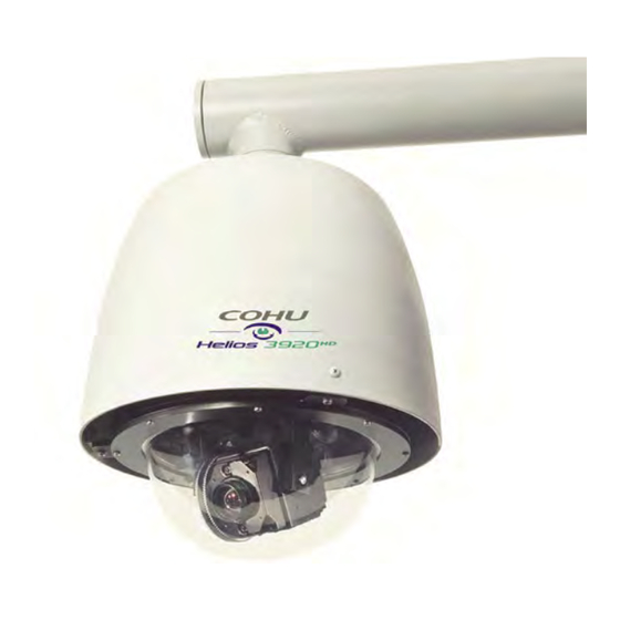
1.0 Introduction (High Definition) and 3920 (Standard Definition) Cam- The CohuHD 3920 era Systems are IP camera systems in environmentally sealed and pressurized dome enclosures. The camera system provides IP video streams with H.264 and MJPEG compression plus an analog composite video output. The camera includes variable a hi-speed pan and tilt drive with 360°continuous pan and +5°... -
Page 7: Equipment Supplied
1.2 Equipment Supplied The camera system is supplied with: • An 18-pin MS type metal connector. The supplied connector is to be wired to the system intercon- nection cable. For more information on the connector see chapter 2.2 of this manual. Optional Accessories The following optional mounts and cables are recommended by CohuHD for camera system installation and can be purchased with the Camera:... - Page 8 Properly secure the camera system before the power is applied. Default IP Address 192.168.2.150 System Cable Cable Shield(s) Router/Switch CAT5e Router/Switch Cable Power Earth Network Ground Switch Figure 1. Interconnection Diagram, IP Output Properly secure the camera system before the power is applied. Default IP Address 192.168.2.150 System Cable...
-
Page 9: System Cable Requirements
2.1 System Cable Requirements To build the Camera system cable CohuHD recommends: • For Ethernet: CAT5e or better cable is recommended. For distances up to a maximum of 100 me- ters (328 feet), use CAT5e cable with four pairs of copper wire, 24 AWG. • For Analog Video: The coax for analog video should be rated at 75 ohms, and should not exceed a maximum attenuation of 6dB at 10MHz for the length of coax required. For example, Belden 9221 miniature coax is a small, extremely flexible, 75 ohm coax that has an attenuation of 2.2dB per 100 feet. It should never be used for distances longer than 270 feet ((6dB / 2.2dB) x 100ft. = 272 feet). An excellent mid range coax would be the Belden 8241F (RG-59/U type with 100% copper core), with an attenuation of 0.9dB per 100 feet, or a maximum recommended distance of 650 feet. For longer cable runs, the Belden 8238 (RG-11/U type) has an attenuation of 0.7dB per 100 feet, which would allow for a maximum cable length of over 850 feet. There are triaxial cables available that can accommodate even longer cable distances, but a video cable equalizer or fiber optics may prove to be more cost effective as a long distance solution. • For Data: Shielded, two twisted pair data cable is recommended. For lower baud rates (9,600 or less), the Belden 8723 shielded cable is usually suitable for distances up to 750 feet. For longer cable runs, and/or faster baud rates, a cable with a lower capacitance per foot should be selected. The Belden 8162 (12.5pf/ft. capacitance), would be suitable for distances well in excess of 1,000 feet at baud rates up to 115KB. -
Page 10: Alarm I/O (Future)
In the 3920 /3920 series Cameras the RS-422 interface is used for sending and receiving serial data. Therefore, a RS-232/422 converter should be used between the Camera and a computer. Figure 3 shows a typical RS-232/422 converter from B&B that could be used with 3920 /3920 . Table 3 shows cable wiring between the Camera and a converter. B&B converter 422PP9TB... -
Page 11: 18-Pin Ms Connector And Its Mating System Cable Connector
2.2 18-pin MS Connector and Its Mating System Cable Connector All system electrical connections for the 3920 /3920 series route through an MS-type metal connector installed in the dome housing. The connector can be wired for 115 V AC or 24 V AC operation. A mating connector is supplied for making system interconnections. -
Page 12: Cohuhd Manufactured System Cables
2.3 CohuHD Manufactured System Cables CohuHD manufactured cables are available for 3920 /3920 series Cameras operating from 115 V AC power or 24 V AC with MS connectors. See table 4. Cables are made with either stripped (prepared) leads or with various combinations of connectors and a RS-232/422 converter. “Stripped” in the tables indicates that the wire leads are stripped and pre-tinned with solder for attachment to a terminal strip or similar device. - Page 13 MS Connector RJ45 Ethernet Video Camera Side Control Side /DATA Alarm RS422 Data Overall Shield 24 V AC Note: NC = No Connection Figure 9. CohuHD Manufactured System Cable CA255S: MS, 24 V AC 6X-1097B...
- Page 14 6X-1097B...
-
Page 15: Mounting Methods
3.0 Mounting Methods The dome camera system is designed for indoor/outdoor installation. The following mounts are recom- mended by CohuHD for 3920 /3920 series installation and can be purchased with the camera. 3.1 Wall Mount Secure with four 5/16” fasteners (not supplied) suitable for the mounting surface End Cap... -
Page 16: Pole Mount
3.2 Pole Mount The pole mount adapter is designed for use with the wall mount (see section 3.1 for a wall mount) . Four 5/16-inch mounting studs (nuts and split lock washers supplied) for attaching the wall mount End Cap 1.5-inch NPT pipe Set Screw Quick Disconnect... -
Page 17: Installation Procedures
3.3 Installation Procedures WARNING: It is the user’s responsibility to ensure that the mounting methods are safe and adequate for the location. For installation: • Use stainless steel hardware to fasten the Camera and mounting brackets. This will ensure the resistance of fasteners to corrosion. - Page 18 • Thread the Quick Disconnect nipple into the mounting arm and tighten with a strap wrench (not supplied). • Tighten the set screw on the mounting arm securely. • Route the system cable down through the nipple and attach the system cable plug to the dome connector.
- Page 19 ø 3.00 (76.20) ø 1.77 (44.95) 1.5 NPT 10.42 (264.66) 8.34 (211.83) 3.32 (84.32) ø 7.00 (177.8) ø 11.05 (280.67) Note: All dimensions in inches (mm). NPT - National Pipe Thread. 3920 /3920 Series Dome Dimensions 6X-1097B...
-
Page 20: Quick Check
4.0 Quick Check 4.1 IP Control and Viewing of Camera Installation and testing of the Camera can be performed with the built-in Helios Web Interface application. The Helios Web Interface was designed to work with Internet Explorer (IE) 8. Microsoft ActiveX® is required to view and control video in the web interface. • Allow the Camera to install Signed ActiveX® control before connecting to the Camera. For more information on ActiveX® control installation see the operation manual 6x-1090, Appendix 1. The manual is shipped with the Camera. For information on computer requirements see section 1.3 of the manual listed above. -
Page 21: Using The Helios Cohuonvifdiscovery Software To Discover The Camera
4.3 Using the Helios CohuONVIFDiscovery Software to Discover the Camera • Download the software from the link below: http://www.CohuHD.com/content/downloads. Under Software & Protocol Downloads see Setup & Test Applications. At Helios ONVIF Discovery Tool click “download here.” • Run the CohuONVIFDiscovery.exe file. Click to start it. • The CohuONVIFDiscovery window will be displayed. -
Page 22: Maintenance
5.0 Maintenance The system is intended for long-term unattended use and the maintenance requirements are minimal: • Clean exterior as needed. • Clean the clear dome on the Camera as needed. • Check pressure periodically. Occasional pressurization of the Camera may be required. See sec- tion 5.1 for more details. -
Page 23: Pressurizing Procedure
5.1.3 Pressurizing Procedure The following items are required for pressurizing: • a tank of dry nitrogen with a regulator • a hose with a strait air chuck to connect to the Schrader valve NOTE: Preferred gas for pressurization is dry nitrogen. Argon is an acceptable substitute. Do not use com- pressed air. - Page 24 Revision History Revision Date Comments Rev A 6/28/2011 Initial release. ECO 031017 • the manual is revised to change company Rev B 7/15/2014 name 6X-1097B...
Need help?
Do you have a question about the 3920HD series and is the answer not in the manual?
Questions and answers