
Related Manuals for KTI Networks KSD-800M Series


Summary of Contents for KTI Networks KSD-800M Series
-
Page 1: Installation Guide
KSD-800M Series Industrial Managed 8-Port Fast Ethernet Switches with Fiber Connectivity Installation Guide DOC.050710... - Page 2 KTI Networks Inc. KTI Networks Inc. reserves the right to revise this documentation and to make changes in content from time to time without obligation on the part of KTI Networks Inc. to provide notification of such revision or change.
- Page 3 The information contained in this document is subject to change without prior notice. Copyright (C). All Rights Reserved. TRADEMARKS Ethernet is a registered trademark of Xerox Corp. WARNING: This equipment has been tested and found to comply with the limits for a Class A digital device, pursuant to Part 15 of the FCC Rules.
-
Page 4: Table Of Contents
2.8 Making UTP Connections ... 22 2.9 Making Fiber Connections ... 23 2.10 LED Indication ... 24 2.11 Configuring IP Address for the Switch ... 25 2.12 Configuring User Name and Password ... 25 2.13 Configuring SNMP Settings ... 25 2.14 Configuring Port 7 and Port 8 ... - Page 5 4.10 Exit ... 45 5. Web Management ... 46 5.1 Start Browser Software and Making Connection ... 46 5.2 Login to the Switch Unit ... 46 5.3 Port Status Menu ... 48 5.4 Administrator ... 49 5.4.1 Basic Menu ... 49 5.4.2 Port Controls ...
-
Page 6: Introduction
1. Introduction The KSD-800M series are managed 8-port full wire speed Fast Ethernet switches for industrial appli- cations. Depending on the fiber connectivity, the series is provided in three types of configuration as follows: Model series 800M 800M-1xxx 800M-2xxx The switches provide the following advantages:... -
Page 7: Features
Panel mounting support for industrial enclosure 1.1 Features Basic functions • Fast Ethernet switch with 8 10/100TX copper ports • Auto MDI/MDI-X detection on all 10/100TX ports • Auto-negotiation capable on all 10/100TX ports • 100FX ports support wide range of fiber options... -
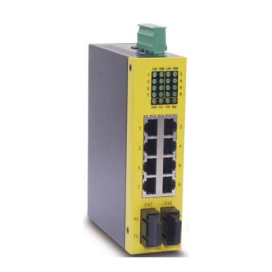
Page 8: Product Panels
1.2 Product Panels The following figure illustrates three major panels of model 800-2 series as example:... -
Page 9: Front Panel
1.3 Front Panel The figure below shows the individual front panel of three model series. The main difference is the number of the equipped fiber ports. 1.4 Network Ports Model 800M provides eight 10/100TX copper ports only. No fiber connectivity is equipped. -
Page 10: Led Indicators
Model 800M-1 series provide eight 10/100TX copper ports and one 100FX fiber connector. Port 8 supports dual network cable types. Model 800M-2 series provide eight 10/100TX copper ports and two 100FX fiber connectors. Port 7 and Port 8 support dual network cable types. 1.5 LED Indicators Function Power status... -
Page 11: Top Panel
The main functions are: DC Power Jack This connector is used when a AC-DC power adapter is used as a power source to the switch. Terminal Block This connector provides the following interfaces: DC1 Positive(+) and Negative(-) - VDC power input from power system... - Page 12 MMF 50/125 60/125, SMF 9/125 Eye safety IEC 825 compliant Optical Specifications Refer to Section 1.8. Switch Functions MAC Addresses Table 1K entries Forwarding & filtering Non-blocking, full wire speed 10Mbps - 14,880 pps at 64-byte packets 100Mbps - 148,800pps at 64-byte packets...
- Page 13 Software Management Functions Interfaces Web, telnet, SNMP MIB-II & private MIB, Traps Management objects Port configuration control and status Username and password settings IP, SNMP related settings VLAN function settings QoS function setting Port Configuration Control Function Configuration P1 ~ P6 Port control function Port TX/RX - enable, disable Port mode - Auto (auto-negotiation), Forced...
-
Page 14: Model Definitions
DC Power Input Interfaces Euro type terminal block contacts (DC1 DC2 : 2 sets for power wire cascading) DC Jack ( -D 6.3mm / + D 2.0mm) Operating Input Voltages +7V ~ +30V(+5%) Power consumption Model 800M Model 800M-1 Model 800M-2 Mechanical Dimension (base) 140 x 106 x 40 mm... - Page 15 Optical Specifications A variety of fiber options and the optical specifications is provided as follows: Model FX Port & Cable 800M-1T FX8 : ST MMF 800M-1C FX8 : SC MMF 800M-1CL1 FX8 : SC MMF 800M-1CL2 FX8 : SC MMF 800M-1SA2 FX8 : SC SMF 800M-1SL2B...
-
Page 16: Installation
2. Installation 2.1 Unpacking The product package contains: • The switch unit • One DIN-rail mounting kit • One product CD-ROM 2.2 Safety Cautions To reduce the risk of bodily injury, electrical shock, fire, and damage to the equipment, observe the following precautions. -
Page 17: Din-Rail Mounting
2.3 DIN-Rail Mounting In the product package, a DIN-rail bracket is provided for mounting the switch in a industrial DIN-rail enclosure. The steps to mount the switch onto a DIN rail are: 1. Install the mounting bracket onto the switch unit as shown below: 2. -
Page 18: Panel Mounting
2.4 Panel Mounting The switches are provided with an optional panel mounting bracket. The bracket support mounting the switch on a plane surface securely. The mounting steps are: 1. Install the mounting bracket on the switch unit. 2. Screw the bracket on the switch unit. - Page 19 3. Screw the switch unit on a panel. Three screw locations are shown below: -19-...
-
Page 20: Applying Power
Using Terminal Blocks Either DC1 interface or DC2 interface can be used to receive DC power from an external power system. Or, DC2 also can be used to deliver the power received on DC1 to next switch in cascading way. -
Page 21: Power Failure Relay Output
Using DC Power Jack When an external power system is not available, the switch provides a DC jack to receive power from typical AC-DC power adapter alternatively. AC Power Adapters: Optional commercial rated adapters are available for purchasing. Rated AC120V/60Hz DC7.5V 1.5A Rated AC230V/50Hz DC7.5V 1.5A... -
Page 22: Reset Button
2.7 Reset Button The reset button is used to perform a reset to the switch. It is not used in normal cases and can be used for diagnostic purpose. If any network hanging problem is suspected, it is useful to push the button to reset the switch without turning off the power. -
Page 23: Making Fiber Connections
FEFI signal sent from the remote link partner. Upon receiving an FEFI signal, it indicates a link failure occurred on the transmitting path. This function allows the switch to report a fiber link fault even when a link failure occurred on transmitting fiber cable. -
Page 24: Led Indication
BLINK Port link is up and there is traffic. Mgt. Factory Reserved Interpretation The power is supplied to the switch. The power is not supplied to the switch. An active link is established on the port. (No traffic) Port link is down. 100Mbps 10Mbps FX7 port is link up. -
Page 25: Configuring Ip Address For The Switch
IP address of the switch : 192.168.0.2 / 255.255.255.0 The IP Address is an identification of the switch in a TCP/IP network. Each switch should be desig- nated a new and unique IP address in the network. Refer to Telnet management interface. -
Page 26: Advanced Functions
3.1.1 Priority Level Each output (egress) port in the switch is equipped with two transmission priority queues to store the packets for transmission. The high priority queue stores the high priority packets and low priority queue stores the low priority packets. -
Page 27: Port-Based Priority Setting (Per Port Setting)
3.1.3.2 802.1p Classification (per port setting) For a received 802.1Q VLAN tagged packet, the switch will check the 3-bit User Priority value in TCI (Tag Control Information) field of packet tag data. If the priority value is equal or larger than a config- ured 802.1p High Priority Tag Setting, the packet is classified as high priority. -
Page 28: Ip Network Address Classification
3.1.3.4 IP Network Address Classification User can configured two IP network address settings, IP(A) and IP(B). If a received IP packet’s source address or destination address belongs to the user defined IP network addresses. The packet is classified as high priority. User Defined IP(A) Classification (Global) Enable - Enable IP(A) checking... -
Page 29: Vlan Function
VLAN related terminologies are described as follows: VLAN Group VLAN group specifies a VLAN information that can be referred by the switch in performing VLAN mapping and packet forwarding for ingress port and the received packets. The information includes: •Group Number : index number of the VLAN group ( 1 ~ 8 ) •VID (VLAN ID) : 12-bit value to indicate a VLAN to which the group is associated (1 ~ 4095) -
Page 30: Ingress Rules
The following sections describe the VLAN processes and related settings provided by the switch. A global setting means the setting is applied to all ports of the switch. A per port setting means each port can be configured for the setting respectively. -
Page 31: Vlan Group Mapping
If the MAC address table lookup is matched and the associated port is the VLAN member port, the packet is forwarded to the port (egress port). If the lookup is not matched, the switch will broadcast the packet to all member ports. -
Page 32: Null Vid Replacement (Per Port Setting)
3.2.5.2 Null VID Replacement (per port setting) The null VID of a Null VID packet will be replaced with the associated ingress port’s PVID. This setting still works even Egress Tag rule : [PVID insertion for untagged packets only] is selected. 3.2.6 Summary of VLAN Function Number of VLAN groups : 8 groups at the same time VLAN ID supported : 1 ~ 4095 (12-bit VID) -
Page 33: Software Management
Telnet function in your Windows PC. Execute Telnet command as follows: >telnet xxx.xxx.xxx.xxx The specified xxx.xxx.xxx.xxx is the IP address of the switch. Factory default IP address is 192.168.0.2. A welcome message and login prompt are displayed if the connection is established properly. -
Page 34: Ip Menu
4.2 IP Menu Select [1] IP Menu to configure IP protocol related settings for the switch. IP Menu: [0] Print this menu [1] Set IP Address [2] View IP status [Q] Back Menu Please Select(0-3)... INET>1 Enter Esc to abort.. -
Page 35: Snmp Menu
Name of the switch for SNMP management Location of the switch for SNMP management Contact person for the switch Community Name allowed for SNMP access to the switch Up to 4 communities can be configured. Access Right associated to the community name, options R(read-only) - only read operation is allowed W(read-write) - both read and write operations are allowed. -
Page 36: Port Config
4.4 Port Config Select [3] Port Config to configure port configuration. Port Config Menu: [0] Print this menu [1] Port Status [2] Port Config [Q] Back Menu Please Select(0-3) Select [1] Port Status to view current port status for all ports as example below: INET>... -
Page 37: Administrator
Speed Control Speed configuration when auto-negotiation is disabled 100M - 100Mbps 10M - 10Mbps Duplex Control Duplex configuration when auto-negotiation is disabled Full - full duplex Half - half duplex Select [2] Port Config to view current port status for all ports as example below: Port Setting Description Ports... - Page 38 VLAN Information VLAN Select Member ports VLAN ID Select [2] VLAN Select to enable or disable VLAN function of the switch. Select [3] VLAN Global Settings to configure 802.1Q Tag Aware Mode and Ingress Member Filter- ing Mode: VLAN Other Settings:...
- Page 39 Valid values : 1 - 4095 Description Enable - Under this mode, the switch will check the content of every received packets. For 802.1Q tagged packets, the tagged VID on the packet is used to look up the VLAN group table and find the group whose VID matches the packet tagged VID.
- Page 40 Select [6] VLAN Per Port Settings to configure VLAN ID for VLAN groups. VLAN Per Port Settings: Port Default Unmatched Group +-----+--------+-----------+---------+---------+ Disabled Disabled Disabled Disabled Disabled Disabled Disabled Disabled +-----+--------+-----------+---------+---------+ Enter Esc to abort.. Please Input Ports (1~8): Per Port Settings Description Ports Input port list for configuration.
-
Page 41: Administrator -> Qos Settings
Disable - Null VID replacement rule is not applied. 4.5.2 Administrator -> QoS Settings Select [4] Administrator -> [2] QoS Settings to configure QoS function related settings for the switch. QoS Settings Menu: [0] Print this menu [1] QoS Per Port Settings... - Page 42 Default TOS/DS classification Enable - If the packets DSCP value is one the default code point Select [2] QoS Other Settings to configure QoS global settings: QoS Other Settings: [0] Print this menu [1] Show QoS Other Status [2] 802.1p priority tag [3] Egress service policy [4] Specific DS Settings [5] Specific IP Settings...
- Page 43 Select [2] - [5] to configure other settings as follows: QoS Other Settings 802.1p priority tag Egress service policy Specific DS(A) Setting Specific DS(A) Value Specific DS(B) Setting Specific DS(B) Value Specific IP(A) Setting Specific IP(A) Value Specific IP(A) Mask Value Specific IP(B) Setting Specific IP(B) Value Specific IP(B) Mask Value...
-
Page 44: Restore Default Values
4.6 Restore Default Values Select [6] Restore Default Values to restore all settings of the switch back to factory default values. Do you want to restore system default settings?(Y/N): Refer to Appendix for factory default values. 4.7 Security Manager Select [7] Security Manager to change user name and password. The user name and password are used for access authentication to the switch in telnet management and web management. -
Page 45: Update Firmware
4.8 Update Firmware Select [7] Update Firmware to update the firmware of the switch. A new firmware may be released by the factory due to function enhancement. The update method is via TFTP protocol. The steps are: 1. A TFTP server must be available in the network before updating the firmware. -
Page 46: Web Management
5.1 Start Browser Software and Making Connection Start your browser software and enter the IP address of the switch unit to which you want to connect. The IP address is used as URL for the browser software to search the device. - Page 47 The following screen shows welcome screen when a successful login is performed. In addition to the device image, the screen supports the following menus on the right side: 1. Home : home page and device image 2. Port Status : view all switched port status 3.
-
Page 48: Port Status Menu
5.3 Port Status Menu Click >Port Status Menu to display the port status for all switched ports. The pop-up port status list is as follows: Port Status Description Port Number 1 - 6 : 10/100TX ports - P1 ~ P2 7 - 8 : 100FX ports - F1 F2 Type Port media type... -
Page 49: Administrator
Set the image refresh time for the web device image Update Firmware Update firmware of the switch Restore Default Restore the switch back to factory default settings Reboot System Reboot the switch 5.4.1 Basic Menu Click Basic menu to configure IP settings and SNMP settings for the switch: -49-... - Page 50 SNMP settings include system settings, community settings and Snmp trap settings as follows: System Settings Description Name Set a system name for the switch Location Set the location where the switch unit is installed Contact Set the contact person for the switch unit -50-...
- Page 51 Community Settings Description Community String Community strings which are allowed to access the switch unit via SNMP protocol Access Right The access right assigned to the community string, options are: RO - read only RW - read / write <<Add>>...
-
Page 52: Port Controls
Button to remove the trap manager Button to enable the switch to send a trap when any port link changes Button to enable the switch to send a trap when any login failure is detected -52-... -
Page 53: Vlan Controls
5.4.3 VLAN Controls VLAN settings are divided into three categories: 1. Global - Settings which are applied for the switch and not for specific ports 2. Group - Settings for VLAN groups 3. Per Port - Settings applied to each port... - Page 54 Enable VLAN - Enable switch VLAN function Disable VLAN - disable switch VLAN function Enable - Under this mode, the switch will check the content of every received packets. For 802.1Q tagged packets, the tagged VID on the packet is used to look up the VLAN group table and find the group whose VID matches the packet’s tagged VID.
- Page 55 Group Settings Description Groups Specify the VLAN group for member port configuration Port Specify the port to be added into or deleted from the specified group. N - unchanged Add - add the port into member port list of the group Del - delete the port from member list of the group Apply Button to confirm the settings...
- Page 56 Per Port Settings -56-...
- Page 57 Per Port Settings Description Port Select port list for configuration. Ingress Rules Default Group Index to the default VLAN group of the selected ports, group 1 ~ 8 Unmatched VID N - unchanged Enable - Drop the tagged packet if the packet VID does not match the ingress port PVID Disable - No Unmatched VID filtering is applied to the port Egress Rules...
-
Page 58: Qos Controls
5.4.4 QoS Controls QoS settings are divided into two categories: 1. Per Port Settings - QoS settings for each port 2. Other Settings - Some global QoS settings QoS Per Port Settings Description Port Select port list for the per port QoS configuration. Port based priority Port based priority classification Enable - All packets received on the port are classified as high priority... - Page 59 QoS Global Settings 802.1p high priority threshold Egress service policy Specific DSCP(A) Specific DSCP(A) Value Specific DSCP(B) Specific DSCP(B) Value Specific IP & Mask (A) Specific IP Address (A) Specific Mask (A) Description 802.1p High Priority Tag Setting for 802.1p classification Valid values : 0 - 7 Weighted Round Robin ratio: 4:1 - 4 high priority packets then 1 low priority packet...
- Page 60 Specific IP & Mask (B) Specific IP Address (B) Specific Mask (B) Apply A received packet on an ingress port is classified as high priority if it meets one the following classifi- cations: 1. The ingress port is enabled for port based high priority. 2.
-
Page 61: Security Manager
5.4.6 Image Refresh Time The switch image shown in web pages is updated periodically to present the latest status. The default time interval of refreshing the image is 20 seconds. It can be changed by clicking any of the time buttons displayed. -
Page 62: Update Firmware
Apply 5.4.8 Restore Default This menu is used to restore all settings of the switch with factory default values. Note that this menu might change the current IP address of the switch and make your current http connection lost. 5.4.9 Reboot System This menu is used to reboot the switch unit with current configuration remotely. -
Page 63: Snmp Management
6. SNMP Management The switch supports SNMP v1 protocol for SNMP management. One device MIB file is provided in the product CD. The MIB file is used for SNMP management software to set or get the management information objects provided in the switch. -
Page 64: Appendix. Factory Default Settings
Appendix. Factory Default Settings IP Settings IP Address IP Subnet mask Gateway IP Security Manager Settings User name Password SNMP Settings System name System location System contact Community string 1 Community string 2-4 Trap manager 1-3 IP Trap manager 1-3 Community Null Login failure trap Port link change trap Port Control Settings... - Page 65 VLAN group 5 VLAN group 6 VLAN group 7 VLAN group 8 Default VLAN group index Unmatched VID Egress tag rule Null VID replacement QoS Settings Port based priority 802.1p classification Default TOS/DS classification Disabled for Port 1 - Port 8 802.1p high priority threshold Egress service policy Specific DSCP (A)