
Related Manuals for KTI Networks KSD-103-B Series


Summary of Contents for KTI Networks KSD-103-B Series
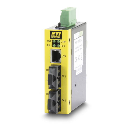
- Page 1 Industrial 3-Port Fast Ethernet Media Converter Switches KSD-103-A series KSD-103-B series Installation Guide DOC.081111 1/20...
- Page 2 (C) 2008 KTI Networks Inc. All rights reserved. No part of this documentation may be reproduced in any form or by any means or used to make any directive work (such as translation or transformation) without permission from KTI Networks Inc.
- Page 3 The information contained in this document is subject to change without prior notice. Copyright (C) All Rights Reserved. TRADEMARKS Ethernet is a registered trademark of Xerox Corp. FCC NOTICE This device complies with Class B Part 15 the FCC Rules. Operation is subject to the following two conditions: (1) This device may not cause harmful interference, and (2) this device must accept any interference received including the interference that may cause.
-
Page 4: Table Of Contents
Table of Contents 1. Introduction..........................5 1.1 Features ......................6 1.2 Product Panels ....................6 1.3 Specifications....................7 2. Installation..........................10 2.1 Unpacking ......................10 2.2 Safety Cautions ....................10 2.3 DIN-Rail Mounting ..................... 11 2.4 Panel Mounting ....................12 2.5 Applying Power .................... -
Page 5: Introduction
1. Introduction The industrial rated KSD-103 Fast Ethernet switch series supports three switching-base segment communications and benefit the following applications and make fiber deployment easier : Copper to fiber bridging converter Multimode fiber to single mode fiber bridging converter Fiber cable extender Cascaded fiber networking Depending on the types of the network ports, two different model series are defined as follows: Model... -
Page 6: Features
High and wide operating Temperature Power input interface: Industrial screw terminal block and DC power jack for external commercial power adapter as option Screw panel and DIN rail mounting support for industrial enclosure Industrial-rated Emission and Immunity performance 1.1 Features Provide 3 switching-base network segments Auto MDI/MDI-X crossover function on the TP copper port Support IEEE 802.3x flow control for full-duplex operation... -
Page 7: Specifications
KSD-103-B 1.3 Specifications Copper Ports Compliance IEEE 802.3 10Base-T, IEEE 802.3u 100Base-TX Connectors Shielded RJ-45 jacks Pin assignments Auto MDI/MDI-X detection Configuration Auto-negotiation Transmission rate 10Mbps, 100Mbps Duplex support Full/Half duplex Network cable Cat.5 UTP up to 100 meters Fiber Ports Connectors ST, SC, VF-45, Bi-Directional SC (model dependent) Configuration... - Page 8 Forwarding & filtering Non-blocking, full wire speed Switching technology Store and forward Maximum packet length 1536 bytes max. Flow control IEEE 802.3x pause frame base for full duplex operation Back pressure for half duplex operation Broadcast Storm Protection design DC Power Interface Interface Screw-type terminal block 1.
- Page 9 Certificate Part 15 Class B CE/EMC EMI EN50081-1 Class B EMS EN55024 CE/LVD Safety EN 60950 EN 50081-1/1992 : EN55022:1994/A1:1995/A2:1997 EN61000-3-2:2000 EN61000-3-3:1995/A1:2001 EN 55024:1998/A1:2001 IEC 61000-4-2:1995 ESD Test IEC 61000-4-3:1995 RS Test IEC 61000-4-4:1995 EFT/BURST Test IEC 61000-4-5:1995 Surge Test IEC 61000-4-6:1996 CS Test IEC 61000-4-8:1993 Magnetic Field IEC 61000-4-11:1994 Voltage Int.
-
Page 10: Installation
2. Installation 2.1 Unpacking Check that the following components have been included: Information CD The device unit DIN-rail mounting bracket If any item is found missing or damaged, please contact your local reseller for replacement. The following are available optional accessories: Panel Mounting Bracket The bracket is used for mounting the device on a panel surface. -
Page 11: Din-Rail Mounting
label. If you are not sure of the type of power source required, consult your service provider or local power company. 2.3 DIN-Rail Mounting In the product package, a DIN-rail bracket is installed on the device for mounting the device in a industrial DIN-rail enclosure. -
Page 12: Panel Mounting
The final mechanical dimensions after installing DIN rail mounting bracket are: 2.4 Panel Mounting The product is provided with an optional bracket for panel mounting. The bracket supports mounting the device on a plane surface securely. The mounting steps are: 1. -
Page 13: Applying Power
2.5 Applying Power The power specifications of the device are: Operating Voltage +7 ~ +50VDC Power Consumption 4W max. @+50VDC Using Terminal Blocks Either DC1 interface or DC2 interface can be used to receive DC power from an external power system. -
Page 14: Failure Alarm Relay Output
If cascading the power to next device is needed, install the power wires and plug for another switch. Then, use DC2 contacts. Note: Only up to four device units can be cascaded to receive power from one main power input source. - Page 15 Use the provided 2P terminal plug for signal wiring and plug into the PF+/- contacts. Relay Output Normal PF+ and PF- contacts shorted Indication Alarm PF+ and PF- contacts open Alarm Events: Input power failure Specific fiber port link down (To specify the fiber ports, use the DIP SW located on bottom.) KSD-103-A Enable broadcast storm protection Disable broadcast storm protection...
-
Page 16: Making Lan Connections
3. Making LAN Connections 3.1 Making Copper Port (RJ-45) Connections The copper ports support the following connection types and distances: Network Cables 10BASE-T: 2-pair UTP Cat. 3,4,5 , EIA/TIA-568B 100-ohm 100BASE-TX: 2-pair / 4-pair UTP Cat. 5, EIA/TIA-568B 100-ohm Link distance: Up to 100 meters Auto MDI/MDI-X Function This function allows the port to auto-detect the twisted-pair signals and adapts itself to form a valid MDI to MDI-X connection with the remote connected device automatically. -
Page 17: Led Indication
3.3 LED Indication KSD-103-A KSD-103-B Function State Interpretation Power status The power is supplied to the device. The power is not supplied to the device. UTPx Copper port link status Port link is established. (No traffic) BLINK Port link is up and there is traffic. Port link is down. -
Page 18: Applications
4. Applications 4.1 Application in Industrial Networks The following figure illustrates an application example in an industrial network. Four devices are cascaded by fiber cables. 4.2 Copper to Fiber Bridging Media Converter Application 4.3 Bridging Multimode to Single Mode Fiber Converter Application 18/20... -
Page 19: Appendix
5. Appendix 5.1 Model Definition KSD-103-A Model Ext. FX Connector Cable Ref. Distance Operating Temperature Duplex ST -10 ~ 70 Duplex SC -10 ~ 70 Duplex SC -20 ~ 70 -SA2 Duplex SC 20km -20 ~ 70 -SL2 Duplex SC 20km -20 ~ 70 -SL3... -
Page 20: Optical Specifications
5.2 Optical Specifications KSD-103-A Model Ext. FX Port Wavelength TX Power Sensitivity RX Max. Power 1310nm -19 ~ -14dBm -31dBm -14dBm 1310nm -19 ~ -14dBm -31dBm -14dBm 1310nm -20 ~ -14dBm -31dBm 0dBm -SA2 1310nm -15 ~ -8dBm -31dBm -7dBm -SL2 1310nm -15 ~ -8dBm...
Need help?
Do you have a question about the KSD-103-B Series and is the answer not in the manual?
Questions and answers