
Subscribe to Our Youtube Channel
Related Manuals for Alliance Laundry Systems AT120FG


Summary of Contents for Alliance Laundry Systems AT120FG
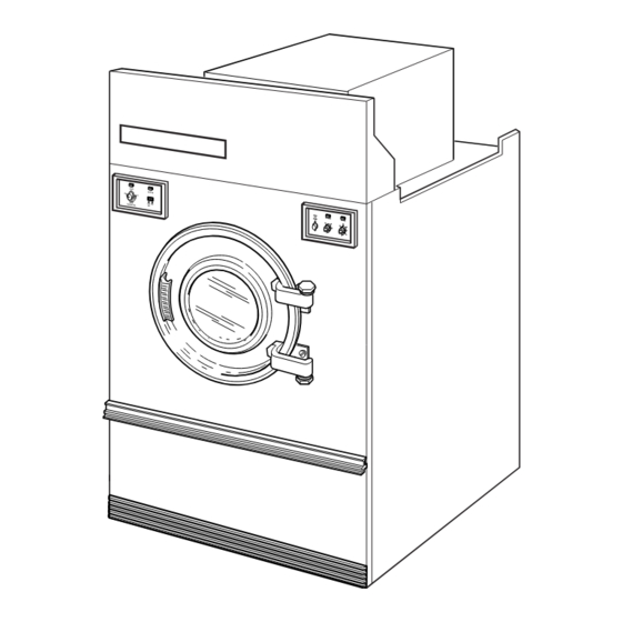
- Page 1 Drying Tumblers 120 Pound Capacity Refer to Page 5 for Model Numbers T021C Part No. M412982R1 www.comlaundry.com April 2002...
-
Page 2: Table Of Contents
All rights reserved. No part of the contents of this book may be reproduced or transmitted in any form or by any means without the expressed written consent of the publisher. © Copyright, Alliance Laundry Systems LLC – DO NOT COPY or TRANSMIT M412982... - Page 3 460-480 VAC, 60 Hertz, 3 Phase Steam ..73 DC, JC and SC Micro Control OM Models 380-415 VAC, 50 Hertz, 3 Phase Gas .....74 380-415 VAC, 50 Hertz, 3 Phase Steam ..75 © Copyright, Alliance Laundry Systems LLC – DO NOT COPY or TRANSMIT M412982...
-
Page 4: Section 1 - Safety Information
• Whenever ground wires are removed during servicing, these ground wires must be reconnected to ensure that the product is properly grounded and to reduce the risk of fire, electric shock, serious injury or death. W006R1 © Copyright, Alliance Laundry Systems LLC – DO NOT COPY or TRANSMIT M412982... -
Page 5: Locating An Authorized Service Person
Locating An Authorized Service Person Alliance Laundry Systems is not responsible for personal injury or property damage resulting from improper service. Review all service information before beginning repairs. Warranty service must be performed by an authorized technician, using authorized factory parts. If service is required after the warranty expires, Alliance Laundry Systems also recommends contacting an authorized technician and using authorized factory parts. -
Page 6: Section 2 - Introduction
Information in this manual is applicable to these models: Steam/Thermal Oil AT120FG AT120CSH DC120FG DC120CSH DT120FG DT120CSH JC120FG JC120CSH JT120FG JT120CSH SC120FG SC120AT ST120FG SC120CSH ST120AT ST120CSH © Copyright, Alliance Laundry Systems LLC – DO NOT COPY or TRANSMIT M412982... -
Page 7: Customer Service
When calling or writing about your product, be sure to mention model and serial numbers. Model and serial numbers are located on serial plate as shown. SERIAL PLATE JUNCTION BOX COVER TMB1497S © Copyright, Alliance Laundry Systems LLC – DO NOT COPY or TRANSMIT M412982... -
Page 8: Safety Warnings And Decals
• Loading door switch MUST be operational before putting tumbler into service. • Junction box cover MUST be reinstalled after inspection or servicing of tumbler is completed. © Copyright, Alliance Laundry Systems LLC – DO NOT COPY or TRANSMIT M412982... -
Page 9: Section 3 - Troubleshooting
Inoperative timer. • Test timer and replace if inoperative. Broken, loose or incorrect wiring. • Refer to wiring diagram located on back of tumbler or in literature packet. © Copyright, Alliance Laundry Systems LLC – DO NOT COPY or TRANSMIT M412982... -
Page 10: Motor Overload Protector Cycles Repeatedly
Incorrect wiring. • Refer to wiring diagram located on back of tumbler or in literature packet. Inoperative motor contactor. • Test motor contactor and replace if inoperative. © Copyright, Alliance Laundry Systems LLC – DO NOT COPY or TRANSMIT M412982... -
Page 11: Gas Burner Does Not Ignite
• Refer to wiring diagram located on back of tumbler or in literature packet. Improper fan rotation. • May be due to improper wiring resulting in low air flow. Refer to Installation Manual. © Copyright, Alliance Laundry Systems LLC – DO NOT COPY or TRANSMIT M412982... -
Page 12: Burner Ignites And Goes Out Repeatedly
• Refer to wiring diagram located on back of tumbler or in literature packet. Improper fan rotation. • May be due to improper wiring resulting in low air flow. Refer to Installation Manual. © Copyright, Alliance Laundry Systems LLC – DO NOT COPY or TRANSMIT M412982... -
Page 13: Burner Repeatedly Cycles Off On High Limit Thermostat
• Replace gas valve or disassemble and clean steam valve. valve from closing. Inoperative drying timer. • Replace timer. Incorrect wiring. • Refer to wiring diagram located on back of tumbler or in literature packet. © Copyright, Alliance Laundry Systems LLC – DO NOT COPY or TRANSMIT M412982... -
Page 14: Clothes Do Not Dry
Restricted or inadequate exhaust system. • Remove obstruction or lint build-up from exhaust ductwork. Refer to the Installation Manual (supplied with tumbler) for exhaust system requirements. Inoperative thermostat. • Replace thermostat. © Copyright, Alliance Laundry Systems LLC – DO NOT COPY or TRANSMIT M412982... -
Page 15: Burners Not Burning Properly - Gas Models
• Check operation of solenoid valve. Incorrect installation of check valve. • Check for inlet and outlet markings on check valve and invert if necessary. Clogged strainer. • Remove strainer and clean. © Copyright, Alliance Laundry Systems LLC – DO NOT COPY or TRANSMIT M412982... -
Page 16: Water In Steam Line - Steam Models
Trap functioning improperly. • Check trap for size and capacity. If trap is dirty or sluggish, clean thoroughly or replace. Check return line for high back pressure. © Copyright, Alliance Laundry Systems LLC – DO NOT COPY or TRANSMIT M412982... -
Page 17: Tumbler Will Not Start, Time On Drying Timer, Door Closed
VOLTS OUT OF SWITCH COIL PUSH-TO-START SWITCH. CHECK FOR CHECK FOR BROKEN WIRE BROKEN WIRE REPLACE OR POOR FROM CONTROL PUSH-TO-START CONNECTION AT RELAY TERMINAL 1 SWITCH HARNESS PLUG © Copyright, Alliance Laundry Systems LLC – DO NOT COPY or TRANSMIT M412982... -
Page 18: Motor Runs But Will Not Heat
GAS SHUT-OFF VALVE TURNED ON VALVE 120 VOLTS REPLACE PRESENT ON IEI CONTROL BLACK WIRE FROM IEI CONTROL CHECK GAS VALVE REPLACE COIL FOR OPEN GAS VALVE CIRCUIT © Copyright, Alliance Laundry Systems LLC – DO NOT COPY or TRANSMIT M412982... -
Page 19: Cylinder Turns, But Will Not Heat
TERMINAL OF STOVE HIGH LIMIT LOOSE WIRE TO RELAY THERMOSTAT 120 VOLTS PRESENT AT INPUT REPLACE STOVE HIGH LIMIT TERMINAL OF STOVE HIGH LIMIT THERMOSTAT THERMOSTAT (continued on following page) © Copyright, Alliance Laundry Systems LLC – DO NOT COPY or TRANSMIT M412982... - Page 20 TO FAN MOTOR CONTACT 120 VOLTS PRESENT ON INPUT TERMINAL OF FAN CONTACTOR AUX REPLACE FAN CONTACTOR CONTACT CHECK FOR BROKEN OR LOOSE JUMPER WIRE TO CONTACTOR CONTACTS © Copyright, Alliance Laundry Systems LLC – DO NOT COPY or TRANSMIT M412982...
-
Page 21: Section 4 - Grounding
To reduce the risk of electrical shock, de- energize the electrical circuit being connected to the tumbler before making any electrical connections. Never attempt to connect a live circuit. W070 © Copyright, Alliance Laundry Systems LLC – DO NOT COPY or TRANSMIT M412982... -
Page 22: Section 5 - Service Procedures
NOTE: Nylon washer must be in place above lower hinge bracket when reinstalling loading door. ACCESS PANEL ACCESS PANEL ATTACHING SCREWS THERMOSTAT TIMER BOX PANEL COVER TIMER PANEL TMB1498S TMB1498S Figure 1 © Copyright, Alliance Laundry Systems LLC – DO NOT COPY or TRANSMIT M412982... -
Page 23: Loading Door Hinges
Remove door switch actuator from upper hinge. TOP VIEW OF TUMBLER REAR IGNITION CONTROL NOTE: CONTROL FUSE BOX COVER HOLDER REMOVED. SIGNAL CONTROL BOX BUZZER COVER FRONT T217SE3B Figure 2 © Copyright, Alliance Laundry Systems LLC – DO NOT COPY or TRANSMIT M412982... -
Page 24: Front Panel
Set aside temperature graphic panel to prevent damage. FRONT PANEL LOADING ATTACHING DOOR SCREWS ASSEMBLY HINGE DOOR HANDLE DOOR HINGES ACTUATOR WASHER DOOR HINGES HINGE DOOR HINGE T248PZ3C BRACKETS TMB1496S Figure 3 © Copyright, Alliance Laundry Systems LLC – DO NOT COPY or TRANSMIT M412982... -
Page 25: Loading Door Switch
Disconnect wires from relay. e. Remove two screws holding relay to bracket. T315PE1A Refer to Figure 5. Figure 4 NOTE: Refer to wiring diagram when rewiring relay. © Copyright, Alliance Laundry Systems LLC – DO NOT COPY or TRANSMIT M412982... -
Page 26: Cooling And Drying Timers
TIMER WIRE LEADS COOLING LIGHT IGNITION RESET SWITCH GRAPHIC PANEL DRYING TIMER START SWITCH MOUNTING SCREW WIRE TIMER LEADS MOUNTING SCREW LIGHT TIMER KNOBS TMB1337P Figure 5 © Copyright, Alliance Laundry Systems LLC – DO NOT COPY or TRANSMIT M412982... -
Page 27: Reversing/Nonreversing Switch
Remove control box cover. Refer to Figure 2. Refer to Figure 7 d. Pull knob off thermostat. Refer to Figure 6. a. Remove micro control face plate. e. Disconnect wires from thermostat. © Copyright, Alliance Laundry Systems LLC – DO NOT COPY or TRANSMIT M412982... -
Page 28: Micro Control
Wrist strap, cord and alligator clip are designed to carry away any electrostatic charge from your body and to direct charge to an available ground. © Copyright, Alliance Laundry Systems LLC – DO NOT COPY or TRANSMIT M412982... - Page 29 P L A S IG IA L T IM S T O IN G T IM IA L IT IO TMB1326P MICRO CONTROL OM MODELS Figure 8 © Copyright, Alliance Laundry Systems LLC – DO NOT COPY or TRANSMIT M412982...
-
Page 30: Emergency Stop Button - Dc, Jc And Sc Models
Remove control box cover. Refer to Figure 2. or Figure 8. d. Disconnect buzzer wires. Refer to Figure 2. e. Remove screws holding buzzer to housing. © Copyright, Alliance Laundry Systems LLC – DO NOT COPY or TRANSMIT M412982... - Page 31 Section 5 Service Procedures SENSING PROBE LINT SCREEN THERMISTOR LINT TMB1746S SCREEN Figure 9 © Copyright, Alliance Laundry Systems LLC – DO NOT COPY or TRANSMIT M412982...
-
Page 32: Gas Valve
Remove two screws attaching igniter bracket to will be injected directly down the center of center burner tube. the burner. W269R1 40. IGNITION CONTROL a. Remove four screws holding access panel to cabinet. © Copyright, Alliance Laundry Systems LLC – DO NOT COPY or TRANSMIT M412982... -
Page 33: Stove High Limit Thermostat
Remove two screws holding thermostat to rear e. Disconnect wires to thermostat. of tumbler. Refer to Figure 14. f. Remove the two thermostat attaching screws. Refer to Figure 10. © Copyright, Alliance Laundry Systems LLC – DO NOT COPY or TRANSMIT M412982... -
Page 34: Steam Coils
Remove steam coils by lifting straight up and out of tumbler. NOTE: When removing or replacing steam coils, be careful not to damage fins on steam coils. TMB1740P Figure 12 © Copyright, Alliance Laundry Systems LLC – DO NOT COPY or TRANSMIT M412982... -
Page 35: Drive Guard Cover
Support drive guard cover and remove screws that hold guard to rear of tumbler. Refer to Figure 13. b. Reinstall drive guard. DRIVE GUARD ATTACHING SCREWS DRIVE GUARD COVER T245PE3B Figure 13 © Copyright, Alliance Laundry Systems LLC – DO NOT COPY or TRANSMIT M412982... -
Page 36: Cylinder Belt
Install new belts as a set of 3. ATTACHING BOLTS JACKSHAFT EYE BOLT ADJUSTING JACKSHAFT NUTS EYE BOLT JACKSHAFT ASSEMBLY LOAD CABINET READY HIGH LIMIT THERMOSTAT THERMOSTAT T316PE3A Figure 14 © Copyright, Alliance Laundry Systems LLC – DO NOT COPY or TRANSMIT M412982... -
Page 37: Drive Belt
T317PE1A screws. Refer to Figure 14. Figure 15 c. Rotate the adjusting nuts counterclockwise (approximately three turns). d. Slide jackshaft assembly upwards to loosen the cylinder belts. © Copyright, Alliance Laundry Systems LLC – DO NOT COPY or TRANSMIT M412982... -
Page 38: Motor Pulley
NOTE: After installing sheave, adjust belts. clear cabinet sides. NOTE: After reinstalling drive and cylinder belts, adjust belts. SETSCREW TAPERED MOTOR BUSHING PULLEY SCREWS T371PE1A Figure 16 © Copyright, Alliance Laundry Systems LLC – DO NOT COPY or TRANSMIT M412982... -
Page 39: Trunnion Bearings
BEARING MOUNTING REAR ADJUSTING SCREW MOUNTING BRACKET BEARING MOUNTING SCREW MOUNTING BRACKET ATTACHING SCREW SETSCREWS FRONT BEARING ASSEMBLY FRONT ADJUSTING SCREW REAR BEARING ASSEMBLY T533P Figure 17 © Copyright, Alliance Laundry Systems LLC – DO NOT COPY or TRANSMIT M412982... -
Page 40: Fan Motor And Fan Assembly
“d” into the threaded holes in the bushing. Turning the screws inward will force the bushing off of the fan. f. Remove fan from motor shaft. © Copyright, Alliance Laundry Systems LLC – DO NOT COPY or TRANSMIT M412982... -
Page 41: Trunnion Shaft Assembly
TRUNNION SHAFT MEASURE AT FOUR POINTS TAPE MEASURE TRUNNION CYLINDER T089SE1A Figure 19 © Copyright, Alliance Laundry Systems LLC – DO NOT COPY or TRANSMIT M412982... -
Page 42: Cylinder Drive Motor
Refer to Figure 20. ATTACHING MOTOR SCREW MOTOR PULLEY MOTOR MOUNTING BRACKET ATTACHING T237PE3E Figure 20 © Copyright, Alliance Laundry Systems LLC – DO NOT COPY or TRANSMIT M412982... -
Page 43: Reversing Timer
Remove transformer. NOTE: Refer to wiring diagram when rewiring reversing contactor. c. Remove screws holding reversing contactor to back wall of contactor box. d. Remove reversing contactor. © Copyright, Alliance Laundry Systems LLC – DO NOT COPY or TRANSMIT M412982... - Page 44 Section 5 Service Procedures Contactor Box REVERSING CONTACTOR REVERSING TRANSFORMER TIMER FAN MOTOR CONTACTOR TERMINAL BLOCK RAIL TERMINAL STRIP T341PE3B Figure 21 © Copyright, Alliance Laundry Systems LLC – DO NOT COPY or TRANSMIT M412982...
-
Page 45: Section 6 - Adjustments
Place a level on the rib. b. Check the side to side level by placing a level on access panel top and rear frame top angle. © Copyright, Alliance Laundry Systems LLC – DO NOT COPY or TRANSMIT M412982... -
Page 46: Main Gas Burner Air Inlet Shutters
Adjust the air shutter as follows: INSUFFICIENT AIRFLOW AIR SHUTTER ADJUSTING SCREW T197SE3C PROPER AIRFLOW AIR SHUTTER ADJUSTING SCREW T196SE3C NO AIRFLOW AIR SHUTTER ADJUSTING SCREW T195SE3C Figure 22 © Copyright, Alliance Laundry Systems LLC – DO NOT COPY or TRANSMIT M412982... -
Page 47: Airflow Switch
Close door and start tumbler, then slowly open Figure 24 loading door. Cylinder and heat system should shut off when door is open 2.75 inches (70 mm) maximum. © Copyright, Alliance Laundry Systems LLC – DO NOT COPY or TRANSMIT M412982... -
Page 48: Drive Belt Tension
Support drive guard cover and remove screws holding guard to rear of tumbler. Refer to Figure 13. SIDE BRACKET MOTOR BRACKET PIVOT SCREW MOTOR MOUNTING BRACKET ADJUSTING NUTS ADJUSTING TUBE T237PE3F Figure 25 © Copyright, Alliance Laundry Systems LLC – DO NOT COPY or TRANSMIT M412982... -
Page 49: Cylinder Belt
Turn both screws Figure 26 evenly to adjust top and bottom clearance. Turn one or the other adjusting screw in or out to adjust side clearance. © Copyright, Alliance Laundry Systems LLC – DO NOT COPY or TRANSMIT M412982... - Page 50 CYLINDER CYLINDER 8/32" ± 3/32" CYLINDER RIM / 9/32" ± 1/32" FRONT PANEL FLANGE CLEARANCE FRONT PANEL FLANGE (Top Shown) FORE / AFT CLEARANCE T218SE3A Figure 27 © Copyright, Alliance Laundry Systems LLC – DO NOT COPY or TRANSMIT M412982...
- Page 51 Section 6 Adjustments ADJUSTING SCREW LOCKNUT REAR ADJUSTING SCREW REAR BEARING MOUNTING SCREW TMB1500S FRONT FRONT ADJUSTING BEARING ASSEMBLY REAR SCREW COLLAR BEARING ASSEMBLY COLLAR Figure 28 © Copyright, Alliance Laundry Systems LLC – DO NOT COPY or TRANSMIT M412982...
-
Page 52: Section 7 - Wiring Schematics
W030 WIRING DIAGRAMS AND SCHEMATICS FOUND ON THE FOLLOWING PAGES ARE FOR MODELS COVERED IN THIS MANUAL. © Copyright, Alliance Laundry Systems LLC – DO NOT COPY or TRANSMIT M412982... -
Page 53: At, Dt, Jt And St Manual Timer Models 208-230 Vac, 60 Hertz, 3 Phase Gas
W030 AT, DT, JT AND ST MANUAL TIMER MODELS 208-230 VAC, 60 HERTZ, 3 PHASE GAS TUMBLER © Copyright, Alliance Laundry Systems LLC – DO NOT COPY or TRANSMIT M412982... -
Page 54: 380-415 Vac, 50 Hertz, 3 Phase Gas
W030 AT, DT, JT AND ST MANUAL TIMER MODELS 380-415 VAC, 50 HERTZ, 3 PHASE GAS TUMBLER © Copyright, Alliance Laundry Systems LLC – DO NOT COPY or TRANSMIT M412982... -
Page 55: 460 Vac, 60 Hertz, 3 Phase Gas
W030 AT, DT, JT AND ST MANUAL TIMER MODELS 460 VAC, 60 HERTZ, 3 PHASE GAS TUMBLER © Copyright, Alliance Laundry Systems LLC – DO NOT COPY or TRANSMIT M412982... -
Page 56: 208-230 Vac, 60 Hertz, 3 Phase Steam
W030 AT, DT, JT AND ST MANUAL TIMER MODELS 208-230 VAC, 60 HERTZ, 3 PHASE STEAM TUMBLER © Copyright, Alliance Laundry Systems LLC – DO NOT COPY or TRANSMIT M412982... -
Page 57: 380-415 Vac, 50 Hertz, 3 Phase Steam
W030 AT, DT, JT AND ST MANUAL TIMER MODELS 380-415 VAC, 50 HERTZ, 3 PHASE STEAM TUMBLER © Copyright, Alliance Laundry Systems LLC – DO NOT COPY or TRANSMIT M412982... -
Page 58: 460 Vac, 60 Hertz, 3 Phase Steam
W030 AT, DT, JT AND ST MANUAL TIMER MODELS 460 VAC, 60 HERTZ, 3 PHASE STEAM TUMBLER © Copyright, Alliance Laundry Systems LLC – DO NOT COPY or TRANSMIT M412982... -
Page 59: Dc, Jc And Sc Manual Timer Models 380-415 Vac, 50 Hertz, 3 Phase Gas
W030 DC, JC AND SC MANUAL TIMER MODELS 380-415 VAC, 50 HERTZ, 3 PHASE GAS TUMBLER © Copyright, Alliance Laundry Systems LLC – DO NOT COPY or TRANSMIT M412982... -
Page 60: 380-415 Vac, 50 Hertz, 3 Phase Steam
W030 DC, JC AND SC MANUAL TIMER MODELS 380-415 VAC, 50 HERTZ, 3 PHASE STEAM TUMBLER © Copyright, Alliance Laundry Systems LLC – DO NOT COPY or TRANSMIT M412982... -
Page 61: Micro Control Mm Models 208-240 Vac, 60 Hertz, 3 Phase Gas
Failure to install, maintain, and/or operate this machine according to the manufacturer's instructions may result in conditions which can produce bodily injury and/or property damage. W030 MICRO CONTROL MM MODELS 208-240 VAC, 60 HERTZ, 3 PHASE GAS TUMBLER © Copyright, Alliance Laundry Systems LLC – DO NOT COPY or TRANSMIT M412982... -
Page 62: 480 Vac, 60 Hertz, 3 Phase Gas
Failure to install, maintain, and/or operate this machine according to the manufacturer's instructions may result in conditions which can produce bodily injury and/or property damage. W030 MICRO CONTROL MM MODELS 480 VAC, 60 HERTZ, 3 PHASE GAS TUMBLER © Copyright, Alliance Laundry Systems LLC – DO NOT COPY or TRANSMIT M412982... -
Page 63: 208-240 Vac, 60 Hertz, 3 Phase Steam
Failure to install, maintain, and/or operate this machine according to the manufacturer's instructions may result in conditions which can produce bodily injury and/or property damage. W030 MICRO CONTROL MM MODELS 208-240 VAC, 60 HERTZ, 3 PHASE STEAM TUMBLER © Copyright, Alliance Laundry Systems LLC – DO NOT COPY or TRANSMIT M412982... -
Page 64: 480 Vac, 60 Hertz, 3 Phase Steam
Failure to install, maintain, and/or operate this machine according to the manufacturer's instructions may result in conditions which can produce bodily injury and/or property damage. W030 MICRO CONTROL MM MODELS 480 VAC, 60 HERTZ, 3 PHASE STEAM TUMBLER © Copyright, Alliance Laundry Systems LLC – DO NOT COPY or TRANSMIT M412982... -
Page 65: At, Dt, Jt And St Micro Control Om Models 208-230 Vac, 60 Hertz, 3 Phase Gas
W030 AT, DT, JT AND ST MICRO CONTROL OM MODELS 208-230 VAC, 60 HERTZ, 3 PHASE GAS TUMBLER © Copyright, Alliance Laundry Systems LLC – DO NOT COPY or TRANSMIT M412982... -
Page 66: 380-415 Vac, 50 Hertz, 3 Phase Gas
W030 AT, DT, JT AND ST MICRO CONTROL OM MODELS 380-415 VAC, 50 HERTZ, 3 PHASE GAS TUMBLER © Copyright, Alliance Laundry Systems LLC – DO NOT COPY or TRANSMIT M412982... -
Page 67: 460-480 Vac, 60 Hertz, 3 Phase Gas
W030 AT, DT, JT AND ST MICRO CONTROL OM MODELS 460-480 VAC, 60 HERTZ, 3 PHASE GAS TUMBLER © Copyright, Alliance Laundry Systems LLC – DO NOT COPY or TRANSMIT M412982... -
Page 68: 208-230 Vac, 60 Hertz, 3 Phase Steam
W030 AT, DT, JT AND ST MICRO CONTROL OM MODELS 208-230 VAC, 60 HERTZ, 3 PHASE STEAM TUMBLER © Copyright, Alliance Laundry Systems LLC – DO NOT COPY or TRANSMIT M412982... -
Page 69: 380-415 Vac, 50 Hertz, 3 Phase Steam
W030 AT, DT, JT AND ST MICRO CONTROL OM MODELS 380-415 VAC, 50 HERTZ, 3 PHASE STEAM TUMBLER © Copyright, Alliance Laundry Systems LLC – DO NOT COPY or TRANSMIT M412982... -
Page 70: 460-480 Vac, 60 Hertz, 3 Phase Steam
W030 AT, DT, JT AND ST MICRO CONTROL OM MODELS 460-480 VAC, 60 HERTZ, 3 PHASE STEAM TUMBLER © Copyright, Alliance Laundry Systems LLC – DO NOT COPY or TRANSMIT M412982... -
Page 71: Dc, Jc And Sc Micro Control Om Models 380-415 Vac, 50 Hertz, 3 Phase Gas
W030 DC, JC AND SC MICRO CONTROL OM MODELS 380-415 VAC, 50 HERTZ, 3 PHASE GAS TUMBLER © Copyright, Alliance Laundry Systems LLC – DO NOT COPY or TRANSMIT M412982... -
Page 72: 380-415 Vac, 50 Hertz, 3 Phase Steam
W030 DC, JC AND SC MICRO CONTROL OM MODELS 380-415 VAC, 50 HERTZ, 3 PHASE STEAM TUMBLER © Copyright, Alliance Laundry Systems LLC – DO NOT COPY or TRANSMIT M412982...
Need help?
Do you have a question about the AT120FG and is the answer not in the manual?
Questions and answers