Table of Contents
Advertisement
Available languages
Available languages
Quick Links
Sine wave Inverter, Battery charger, Transfersystem
Kombigerät mit Sinuswechselrichter Batterielader, Transferschaltung
Manuel d'utilisation et de montage
Onduleur, Chargeur de batterie, Système de transfert
XP-COMPACT - XPC 1400-12
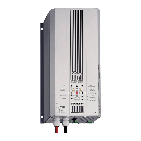
XP-COMPACT - XPC 2200-24
XP-COMPACT - XPC 2200-48
Temperature sensor, Temperatursonde, Sonde de temperature CT-35
Remote control, Fernsteuerung, Télécommande RCC-01
Solar charge regulator, Solarladeregler, Régulateur solaire Cxxxx-S
AC cable cover, Kabeleinführung, Capot pour câbles AC CFC-01
IP-23 top cover, Abdeckung, Capot C-IP23
STUDER INNOTEC
Rue des Casernes 57
CH – 1950 Sion
User's and installer's Manual
Betriebs- und Montageanleitung
TEL : ++41 (0)27 205 60 80
FAX : ++41 (0)27 205 60 88
E-MAIL :
info@studer-innotec.com
80527
Advertisement
Table of Contents

Related Manuals for Studer XP-COMPACT-XPC 1400-12


Summary of Contents for Studer XP-COMPACT-XPC 1400-12
- Page 1 Solar charge regulator, Solarladeregler, Régulateur solaire Cxxxx-S AC cable cover, Kabeleinführung, Capot pour câbles AC CFC-01 IP-23 top cover, Abdeckung, Capot C-IP23 STUDER INNOTEC TEL : ++41 (0)27 205 60 80 Rue des Casernes 57 FAX : ++41 (0)27 205 60 88 CH –...
-
Page 2: Table Of Contents
STUDER Innotec XP-COMPACT English description ........................5 General Information ..................5 Operating instructions ..................5 Quality and Warranty ..................5 Warranty Disclaimer ................... 5 Liability Disclaimer ....................6 Warning ........................ 6 Special precautions .................... 6 Introduction ......................7 Principle schematic .................... 7 Description of the main functions .............. - Page 3 STUDER Innotec XP-COMPACT Deutsche Beschreibung ....................... 29 Allgemeine Informationen ................29 Zu dieser Bedienungsanleitung ..............29 Qualität und Garantie ..................29 Garantieausschluss ..................29 Haftungsausschluss ..................30 Warnungen ......................30 Besondere Schutzmassnahmen ..............31 Einführung ......................32 Prinzip Schema ....................32 Beschreibung der Hauptfunktionen ...............
- Page 4 STUDER Innotec XP-COMPACT Instructions en français ......................55 Informations générales ................. 55 Manuel d’utilisation ................... 55 Qualité et garantie .................... 55 Exclusion de garantie ..................55 Exclusion de la responsabilité ................ 56 Avertissements ....................56 Mesures de protection particulière ..............56 Introduction ......................
-
Page 5: English Description
− Running liquid or oxidation through condensation in the appliance − Defects caused by force, physical or mechanical means − Changes not explicitly authorized by STUDER INNOTEC − Not or only partly tightened screws and nuts after change of fuses or cables connecting −... -
Page 6: Liability Disclaimer
Liability Disclaimer Respecting this manual, servicing and method of installation, functioning, application and maintenance of the appliance can not be controlled or supervised by STUDER INNOTEC. Hence we do not accept any liability and responsibility for damages, losses and costs which result through the use of this appliance or which result through incorrect installation, incorrect operation or wrong application and maintenance, or which by some other means maybe connected to each other. -
Page 7: Introduction
STUDER Innotec XP-COMPACT − If acid enters the eyes, you must thoroughly wash them with cold running water for at least 15 minutes. It is recommended that you immediately consult a medical doctor. − Baking powder neutralizes battery acid electrolyte. Always keep some at hand. -
Page 8: Description Of The Main Functions
STUDER Innotec XP-COMPACT (2) Remote control for remote adjustment of the input limit. (see chap. 4.6.3) Description of the main functions 2.2.1 The inverter The sine wave inverter XP-COMPACT generates a sinusoidal AC voltage with an exceptionally precise voltage and stabilized frequency. In order to start large electric motors, the user has the possibility to use a short surge power which is 3 times the nominal power of the XP-COMPACT. -
Page 9: Battery Connecting
STUDER Innotec XP-COMPACT Battery connecting Lead-acid batteries are normally available in blocks of 2V, 6V or 12V. In most cases, to generate the necessary operating voltage and the capacity of the batteries for the XP-COMPACT many batteries have to be connected together in parallel and or in series. -
Page 10: Mounting And Installing
STUDER Innotec XP-COMPACT Mounting and installing Installation place The location of the XP-COMPACT must be driven by the following criteria: − Protection from unauthorized handling − Dry dust free room, no condensation − Never install directly over the battery and never in a cabinet together with the batteries −... -
Page 11: Connection Plan
STUDER Innotec XP-COMPACT − All cables must be tightly screwed in place. For safety, a yearly control is recommended. In mobile installations control must be carried out more often. − Connecting must be done by qualified personnel. Material such as cable, connectors and distribution boxes, fuses etc. -
Page 12: Cabling
STUDER Innotec XP-COMPACT J ID Plate Identification plate with Technical data and Serial number K AC Output Connection terminal for AC-output L Caution… Caution: Check Polarity (+/-) before connecting the battery ! M Don’t… Do not open without disconnecting all terminals... - Page 13 STUDER Innotec XP-COMPACT 2.5mm2). Connections are marked as follows “N“ Neutral, “PE“ Earth (connected to the appliance enclosure), “L“ Live. Caution: High voltages can be there. Make sure that the XP-COMPACT is turned off (LED 13 lighting) before the connection.
-
Page 14: Control
STUDER Innotec XP-COMPACT Control Display and control parameters Display and control parameters on remote control panel (optional) COMPACT INVERTER - CHARGER TRANSFER AC IN AC OUT CHARGER INVERTER RESET SOLAR CHARGE ALARM (Select) Over Temp. EQUALIZE Overload Program Battery Low/High... -
Page 15: Light Emitting Diodes (Led)
STUDER Innotec XP-COMPACT Light Emitting Diodes (LED) Marking LED lit LED blinks Voltage A voltage outside the self-adjusted corresponding to values is at the AC IN input, or the XP- AC IN self-adjusted COMPACT is in synchronization values is at the AC phases IN input. -
Page 16: Push Buttons
STUDER Innotec XP-COMPACT Display the value of the output power in % of Pnom (in POWER Inverter Mode) and the charge current in Amps (in Charger MONITOR Mode). Push buttons Turning the XP-COMPACT on and off (Help Button for ON/OFF... -
Page 17: The Battery Charger
STUDER Innotec XP-COMPACT If the Inverter has been overloaded for a long time or it has been working in too high surrounding temperatures, it will switch off. The LED 10 „Over Temp.“ is lit and the LED 13 „OFF“ blinks. After cooling down, the inverter switches back on automatically. - Page 18 STUDER Innotec XP-COMPACT The charger functions are shown in the following diagram: 4.7.2 Default values for battery voltage thresholds Absorption Equalization Low voltage Float charge Absorption Equalization time time 24V 48V 12V 24V 48V 12V 24V 48V 12V 24V 48V...
-
Page 19: The Transfer System
STUDER Innotec XP-COMPACT The charging current is displayed on POWER MONITOR (25) of the front panel or on the Remote Control. 4.7.5 Battery Condition Built-in microprocessor with a specially developed algorithm calculates the actual state of charge of the battery and displays it on LED 15 – 18. The LED 14 is lit when the system is carrying out a charge cycle with equalization. -
Page 20: The Solar Charge Controller (Option)
STUDER Innotec XP-COMPACT Battery Charger is working, part of this power is used for charging according to the power sharing system. The Transfer system is protected against overload with a circuit breaker on the AC Input side of the XP-COMPACT. If the system has been overloaded, the button/pin of the fuse will pop out. -
Page 21: 4.10 The Multifunctional Contact
STUDER Innotec XP-COMPACT panels to be connected must match the actual operating voltage of the XP- COMPACT and never exceeds the max. rated value. Under no circumstances should any other systems such as wind-generator be connected at the input of the Solar Charge Controller. -
Page 22: The Remote Control Rcc-01
STUDER Innotec XP-COMPACT 4.11 The Remote Control RCC-01 As an option, a Remote Control can be connected to XP-COMPACT. operating controls displays except from level adjustment are available on Remote Control. Remote Control is supplied with a 20m long cable. It can as long as 40m. -
Page 23: Programming (Possible Only With The Remote Control Rcc-01)
STUDER Innotec XP-COMPACT Programming (possible only with the remote control RCC-01) The XP-COMPACT is equipped with a processor fitted out with a Flash Memory, which means that even when it is disconnected from the battery, the parameters that were programmed for the application remain after a new connection to the battery. -
Page 24: Auxiliary Contact
STUDER Innotec XP-COMPACT With the Push Button 19 (Change status) set the desired parameter (voltage or time) to modify (LED 14/ 15/16/17/18). Push Button 19 (Change status) to set the desired value according to the table 5.3.2. If desired, repeat the operation with any other parameter (voltage or time) to be changed. - Page 25 STUDER Innotec XP-COMPACT − With the Push Button 19 (Change status) confirm or change the status for this condition. If during 30 seconds no buttons are pushed, then the settled values are automatically stored and the XP-COMPACT switches back to normal operating condition.
-
Page 26: Disabling Some Of The Xp-Compact Functions
STUDER Innotec XP-COMPACT 5.4.6 Manual operating of Auxiliary Contact The Auxiliary Contact can be operated at any time with the Push Button 21 (AUX. CONTACT). The LED 6 „Contact manual“ lights up as information that the Contact is manually operated, and LED 5 „Contact active“ lights up when the Contact is active. -
Page 27: Installation Maintenance
Hereby we state that the products described in this user manual comply with the following standards: EN 61000-6-1, EN 61000-6-3, EN 55014, EN 55022, EN 61000-3-2, Dir. 89/336/EEC, LVD 73/23/EEC, EN 50091-2, EN 60950-1. CH - 1950 Sion, the 1st of March 2003 STUDER INNOTEC (R. Studer) XP-COMPACT V5.7 27/79... -
Page 28: Technical Data
STUDER Innotec XP-COMPACT Technical Data XP-COMPACT V5.7 28/79... -
Page 29: Deutsche Beschreibung
− Verpolung bei Batterieanschluss(+/- vertauscht) − In das Gerät eingelaufene Flüssigkeiten oder Oxydation durch Kondensation − Defekte durch mechanische Einflüsse − Nicht ausdrücklich von STUDER INNOTEC autorisierte Änderungen − Nicht oder nur teilweise festgezogene Schrauben und Muttern nach Wechseln von Sicherungen oder Anschlusskabeln. -
Page 30: Haftungsausschluss
Verletzung anderer Rechte Dritter, die aus der Verwendung dieses Gerätes entstehen. Der Einsatz und Betrieb von Geräten von STUDER INNOTEC obliegt in jedem Fall der Verantwortung des Kunden. Die in dieser Beschreibung erwähnten Geräte sind nicht für den Betrieb von lebenserhaltenden Systemen einzusetzen. -
Page 31: Besondere Schutzmassnahmen
STUDER Innotec XP-COMPACT weder Feuer entfacht noch Funken erzeugt werden. Die Batterien müssen in einem gut belüfteten Raum untergebracht sein, und sie müssen so untergebracht sein, dass aus Unachtsamkeit keine Kurzschlüsse auf deren Anschlüssen entstehen können. Versuchen Sie nie gefrorene Batterien zu laden. -
Page 32: Einführung
STUDER Innotec XP-COMPACT Einführung Der XP-COMPACT ist ein Sinuswechselrichter mit integriertem Batterielader mit vielen Zusatzfunktionen für Einsatz netzunabhängiges Wechselstromversorgungssystem oder als unterbrechungsfreie Stromversorgung entwickelt wurde. Prinzip Schema Bemerkung : Der Neutralleiter “N“ des XP-COMPACT ist in keiner Funktionsart mit dem Erdleiter “PE“ verbunden. Falls nötig und wenn es die jeweiligen gültigen Vorschriften verlangen kann die automatische Zuschaltung der Erde mit dem Neutralleiter mit dem Einbringen einer Brücke im Geräteinnern realisiert werden. -
Page 33: Batterie Verschaltungen
STUDER Innotec XP-COMPACT einstellbare Standby- oder Lasterkennungsschaltung sorgt für kleinsten Energieverbrauch und möglichst lange Lebensdauer der Batterie. 2.2.2 Der Transferschalter Der XP-COMPACT kann an eine Wechselstromquelle angeschlossen werden. Zum Beispiel Notstromgeneratoren oder öffentliche Netz. Über Transferschalter steht einerseits diese Wechselspannung am Ausgang für die angeschlossenen Verbraucher zur Verfügung. - Page 34 STUDER Innotec XP-COMPACT 2.3.2 Serieschaltung 2.3.3 Parallel- Serieschaltung XP-COMPACT V5.7 34/79...
-
Page 35: Montage Und Installation
STUDER Innotec XP-COMPACT Montage und Installation Ort der Montage Der Standort des XP-COMPACT muss nach folgenden Kriterien ausgewählt werden: − Geschützt vor unbefugtem Zugriff − Trockener, staubfreier Raum, keine Kondensation − Nie direkt über der Batterie montieren und auch nie in einem Schrank zusammen mit der Batterie −... -
Page 36: Anschlussplan
STUDER Innotec XP-COMPACT − Um die Batteriekabel zu schützen, muss direkt auf der Batterie eine dem Leiterquerschnitt entsprechende Sicherung montiert werden. − Sämtliche Kabel müssen gut festgeschraubt sein. Zur Sicherheit empfehlen wir eine jährliche Kontrolle. Bei mobilen Anlagen sollten die Anschlüsse öfter kontrolliert werden. -
Page 37: Verdrahtung
STUDER Innotec XP-COMPACT G Aux. Contact Anschlussklemmen für den Hilfskontakt H AC Input Anschlussklemmen für Wechselspannungseingang. Direkt über diesen Klemmen liegt der dazugehörige Sicherungsautomat. J Typ… Typenschild mit Leistungsdaten und Seriennummer K AC Output Anschlussklemmen für Wechselspannungsausgang L Caution… Vorsicht: Vor dem Anschliessen der Batterie unbedingt Polarität (+/-) kontrollieren! Faschanschluss kann den... - Page 38 STUDER Innotec XP-COMPACT Anschlüsse entfernt werden; auch die Batterie muss abgeklemmt werden. Arbeitet der XP-COMPACT nach dem Auswechseln der Sicherung und der Richtigstellung der Polarität nicht, ist das Gerät defekt und muss zur Reparatur gesandt werden. 3.6.2 Anschluss der 230Vac-Verbraucher (AC OUT) Die 230V Verbraucher müssen auf den Schraubklemmen AC OUT angeschlossen...
-
Page 39: Bedienung
STUDER Innotec XP-COMPACT Bedienung Anzeigen und Bedienelemente AC OUT AC IN Search mode CHARGER INVERTER Current adj. Standby adj. 100% Off / Alarm ON / Reset Temporary off Solar charge Batt 100% Absorption Equalize Batt undervolt. BATTERY Batt overvolt. Anzeigen und Bedienelemente für der Fernsteuerung (Remote... -
Page 40: Leuchtdioden (Led)
STUDER Innotec XP-COMPACT Leuchtdioden (LED) Bezeichnung LED leuchtet LED blinkt Eine Spannung Eine Spannung, ausserhalb entsprechend den der eingestellten Werte, eingestellten Werten liegt liegt am Eingang AC IN an, AC IN am Eingang AC IN an oder der XP-COMPACT befindet sich in... -
Page 41: Tasten
STUDER Innotec XP-COMPACT Ausgangsleistung in % der Nominalleistung (Betriebsart Power Monitor Wechselrichter) sowie Ladestrom in A (Betriebsart Batt.- Lader) Tasten Ein- bzw. Ausschalten des XP-COMPACT (Hilfstaste für ON/OFF Programm.) RESET ALARM Akustisches Signal aus (Hilfstaste für Programmierung) Manuelle Steuerung des Hilfskontakt (Hilfstaste für Aux. -
Page 42: Der Batterielader
STUDER Innotec XP-COMPACT automatisch ein. Die LED 13 leuchtet dauernd. Ein Wiedereinschalten muss durch Drücken der Taste 19 „ON/OFF“ erfolgen. 4.6.3 Überhitzung Wird der Wechselrichter zu lange überlastet oder wird er bei zu hoher Umgebungstemperatur betrieben, erfolgt seine Abschaltung. Die LED 10 „Over Temp.“... - Page 43 STUDER Innotec XP-COMPACT 4.7.2 Spannungsschwellen der Batterie (Grundeinstellung) Absorptions Egalisie- Unterspannung Schwebeladung Absorption Egalisierung -dauer rungsdauer 48V 12V 24V 48V 12V 24V 48V 12V 24V 48V 12/24/48V 12/24/48V 11.6 23.2 46.4 13.5 27.0 54.0 14.4 28.8 57.6 15.6 31.2 62.4 2 St.
-
Page 44: Der Umschaltautomat (Transferschalter)
STUDER Innotec XP-COMPACT Batteriekapazität eingestellt werden. Das heisst, dass der Ladestrom für eine Batterie mit 200Ah zwischen 20 – 40A eingestellt werden sollte. Der Ladestrom wird auf dem POWER MONITOR (25) und auf der Fernbedienung angezeigt. 4.7.5Batteriezustand Der jeweilige Ladezustand der Batterie wird vom eingebauten Mikroprozessor mit einem speziell dafür entwickelten Algorithmus errechnet und mit... - Page 45 STUDER Innotec XP-COMPACT (TRANSFER) und LED 8 (AC OUT) leuchten. Der Wechselrichter wird aus- und der Batterielader eingeschaltet. Diese Schaltung erfolgt immer automatisch, ausser wenn die Funktion Lader und oder Transfer durch entsprechende Programmierung gesperrt wurde. Der maximale Strom des Transferschalters beträgt 16A. Dass heisst, es können über diesen Schalter Werbraucher bis maximal 3700 Watt betrieben werden.
-
Page 46: Der Solarladeregler (Option)
STUDER Innotec XP-COMPACT usw., bewirkt einen kurzzeitigen Einbruch der Spannung. Da in solchen Fällen eine Umschaltung auf den Wechselrichter nicht sinnvoll ist, kann der Umschaltautomat mit einer Verzögerung programmiert werden. Wenn der Schiebeschalter (Transfer delay) in der Stellung „On“ steht, erfolgt die Umschaltung auf den Wechselrichter mit einer Verzögerung von 5 Sekunden. -
Page 47: Die Fernsteuerung Rcc-01
STUDER Innotec XP-COMPACT > 36Vdc / 3Amp. Das Programmieren des Hilfskontakts ist im Abschnitt Programmierung beschrieben. 4.11 Die Fernsteuerung RCC-01 Option kann eine Fernsteuerung COMPACT angeschlossen werden. Alle Bedienungselemente Anzeigen Ausnahme Pegeleinstellungen sind auf dieser Fernsteuerung vorhanden. Fernsteuerung einem 20m langen Kabel versehen. -
Page 48: Programmierung (Nur Mit Fernsteuerung Rcc-01 Möglich)
STUDER Innotec XP-COMPACT zu korrigieren, kann eine Temperatursonde am XP-COMPACT angeschlossen werden. Die Kompensation durch die Sonde beträgt –3mV/°C/Zelle. Bestellnummer: CT-35 Abmessungen: H x B x T / 58 x 51.5 x 22mm Programmierung (nur mit Fernsteuerung RCC-01 möglich) Hinweis: Der XP-COMPACT ist mit einem Flash-Prozessor mit EEPROM- Speicher ausgerüstet;... - Page 49 STUDER Innotec XP-COMPACT − Die Taste 21 (Programm) zusammen mit der Taste 19 (Change status) mind. 2 Sekunden lang drücken. − Mit Taste (select) ändernde Batterieschwelle oder Absorptionsdauer wählen. − Unterspannung LED 13 − Schwebeladung LED 12 − Absorption (Ladeschluss) LED 11 −...
-
Page 50: Hilfskontakt
STUDER Innotec XP-COMPACT 5.3.2 Liste der möglichen Spannungsschwellen und Zeiten Egali- Schwebeladun Absorp- Unterspannung Absorption Egalisierung sierungs- tionsdauer dauer LED 13 LED 12 LED 11 LED 10 LED 10/11 10/11/12/13 12/24/48 12/24/48 12.0 24.0 48.0 13.7 27.4 54.8 16.2 32.4 64.8 16.2 32.4 64.8 4 St. - Page 51 STUDER Innotec XP-COMPACT 5.4.3 Der Hilfskontakt für den Generatorstart Generatorstart entsprechend der Batteriekapazität Wenn die Batteriekapazität (LED 15 – 18) für die Programmierung des Hilfskontaktes verwendet werden soll, müssen folgende Bedingungen beachtet werden. Wenn bei einer bestimmten Restkapazität der Batterie mit dem Hilfskontakt eine Notstromversorgung gestartet werden soll, müssen zwei Batteriekapazitäten...
-
Page 52: Sperren Von Funktionen
STUDER Innotec XP-COMPACT 5.4.5 Der Hilfskontakt für Verbraucher 2. Priorität Oft ist es sinnvoll, dass Verbraucher mit grosser Leistung oder minderer Priorität nicht oder nur teilweise über den Wechselrichter (Batterie!) betrieben werden. Solche Verbraucher werden am besten mit dem Hilfskontakt zu- resp. abgeschaltet. -
Page 53: Wartung
Hiermit erklären wir, dass die in dieser Anleitung beschriebenen Produkte den folgenden Normen entsprechen: EN 61000-6-1, EN 61000-6-3, EN 55014, EN 55022, EN 61000-3-2, Dir. 89/336/EEC, LVD 73/23/EEC, EN 50091-2, EN 60950-1. CH-1950 Sion den 1. März 2003 STUDER INNOTEC (R. Studer) XP-COMPACT V5.7 53/79... -
Page 54: Technische Daten
STUDER Innotec XP-COMPACT Technische Daten XP-COMPACT V5.7 54/79... -
Page 55: Instructions En Français
− La présence accidentelle de liquides dans l’appareil ou une oxydation consécutive à la condensation − Les défauts consécutifs à des chutes ou à des chocs mécaniques − Des modifications réalisées sans l’autorisation explicite de STUDER INNOTEC XP-COMPACT V5.7 55/79... -
Page 56: Exclusion De La Responsabilité
Nous n'assumons aucune responsabilité pour les violations de droits de brevets ou d'autres droits de tiers résultant de l'utilisation de l’onduleur. STUDER INNOTEC se réserve le droit de toute modification sur le produit sans communication préalable. Avertissements Le présent manuel fait partie intégrante de l’appareil et doit être tenu à... - Page 57 STUDER Innotec XP-COMPACT − Lors de travaux avec des batteries, la présence d’une seconde personne est requise de manière à prêter assistance en cas de problème. − Il doit être gardé à portée de main suffisamment d’eau fraîche et de savon afin de permettre un lavage suffisant et immédiat de la peau ou des yeux entrés...
-
Page 58: Introduction
STUDER Innotec XP-COMPACT Introduction Le XP-COMPACT est un onduleur sinusoïdal avec chargeur de batterie. Il a été développé pour être utilisé comme installation en îlot pour la fourniture de courant AC (pas d’injection dans le réseau) ou comme alimentation sans coupure (UPS). -
Page 59: Câblage De La Batterie
STUDER Innotec XP-COMPACT à 20 watts, il permet la mise en veille de l’onduleur lorsque aucun consommateur n’est utilisé. 2.2.2 Le relais de transfert Le XP-COMPACT peut être raccordé à une source de tension alternative telle que génératrice ou réseau public. Lorsque le relais de transfert est activé, la tension présente à... -
Page 60: Montage Et Installation
STUDER Innotec XP-COMPACT 2.3.1 Raccordement en parallèle 2.3.2 Raccordement en série 2.3.3 Raccordement en série et en parallèle Montage et installation Lieu de montage Le lieu du montage du XP-COMPACT est important et doit satisfaire aux critères suivants : − A l’abri de toute personne non autorisée −... -
Page 61: Fixation
STUDER Innotec XP-COMPACT − Dans des applications mobiles il est important de tenir les vibrations au niveau le plus bas possible Fixation 3.2.1 Fixation du XP-COMPACT De manière générale le XP-COMPACT peut être installé dans n’importe quelle position. Le XP-COMPACT est fixé... -
Page 62: Coffret De Raccordement
STUDER Innotec XP-COMPACT 3.3.2 Capot de protection pour bornes de sorties CFC-01 (option) Un capot de protection avec passe câble est disponible en option (Réf. N° CFC-01). Il peut être requis lorsque l’appareil n’est pas monté dans un local à accès restreint. Il empêche tout contact accidentel sur les bornes Ac out (230 Vac) et les presse étoupes garantissent une bonne reprise des... -
Page 63: Câblage
STUDER Innotec XP-COMPACT J Plaquette signalétique Etiquette sur laquelle figure le type, le N° de série ainsi que les données principales de l’appareil K AC Output Bornes connexion pour la sortie de la tension AC L Caution… Notice d’avertissement : Vérifiez attentivement la polarité... - Page 64 STUDER Innotec XP-COMPACT 3.6.2 Raccordement des consommateurs sur la sortie 230 Vac (AC Output) Les consommateurs 230V doivent être connectés sur les bornes de raccordement « AC OUT » avec des fils d’une section à déterminer selon les normes. Les bornes sont marquées de la manière suivante : N = neutre, L = phase, PE = terre (raccordé...
-
Page 65: Commande
STUDER Innotec XP-COMPACT Commande Affichage et éléments de commande sur l’appareil AC OUT AC IN Search mode CHARGER INVERTER Current adj. Standby adj. 100% Off / Alarm ON / Reset Temporary off Solar charge Batt 100% Absorption Equalize Batt undervolt. -
Page 66: Indicateurs Lumineux (Led)
STUDER Innotec XP-COMPACT Indicateurs lumineux (LED) Inscription LED allumée LED clignotante Une tension AC correcte Une tension insuffisante mais de est présente sur l’entée AC fréquence correcte est présente AC IN sur l’entrée AC, ou le XP- COMPACT est en cours de... -
Page 67: Touches
STUDER Innotec XP-COMPACT Touches Touche de commande marche / arrêt du XP-COMPACT ON/OFF (touche de programmation) RESET Arrêt de l’avertisseur sonore (touche de programmation) ALARM Aux. Commande manuelle du contact auxiliaire (touche de Contact programmation) Bouton de réglage rotatif CHARGER Règle le courant maximum du chargeur... -
Page 68: Le Chargeur De Batterie
STUDER Innotec XP-COMPACT continue. L’onduleur devra dans ce cas être redémarré manuellement à l’aide du bouton ON/OFF (19) après suppression de la cause de l’arrêt. 4.6.3 Surchauffe Si l’onduleur est continuellement surchargé durant une longue période ou que la température environnante est trop élevée, il sera automatiquement arrêté. Dans ce cas la LED 10 «... - Page 69 STUDER Innotec XP-COMPACT 4.7.2 Valeur par défaut des seuils de batterie Tension de Tension Tension Temps Temps Sous-tension maintien d’absorption d’égalisation d’absorption d’égalisation 12V 24V 48V 12V 24V 48V 12V 24V 48V 12V 24V 48V 12/24/48V 12/24/48V 11.6 23.2 46.4 13.5 27.0 54.0 14.4 28.8 57.6 15.6 31.2 62.4 20’...
-
Page 70: Le Relais De Transfert
STUDER Innotec XP-COMPACT 4.7.4 Réglage du courant de charge de la batterie Le courant de charge maximal pour la batterie doit être réglé au moyen du bouton (22) « CHARGER ». Le courant de charge de la batterie devrait être réglé à env. 10–... - Page 71 STUDER Innotec XP-COMPACT AC Input » (1) s’allume. Le relais de transfert entre en fonction, reportant la tension d’entrée sur la sortie AC Output. Les LED « TRANSFER » (7) et « AC Output » (8) sont dès lors allumés. Les consommateurs en service sont alimentés par la source présente à...
-
Page 72: Le Régulateur De Charge Solaire (Option)
STUDER Innotec XP-COMPACT aux situations de sous-tension d’une durée inférieure à 5 secondes. Dans tous les cas, si la tension d’entrée est inférieure à 100Vac, la commutation s’effectue sans délai comme dans le mode non-retardé. Le régulateur de charge solaire (option) Le XP-COMPACT est équipé... -
Page 73: La Télécommande Rcc-01
STUDER Innotec XP-COMPACT 4.11 La télécommande RCC-01 En option, une télécommande peut être raccordée au XP- COMPACT via un câble de 20 mètres inclus. La longueur peut être portée à 40 m au maximum. Tous éléments commande et d’affichage sont disponibles télécommande à... -
Page 74: Programmation (Uniquement Avec La Télécommande Rcc-01)
STUDER Innotec XP-COMPACT COMPACT se déclenchera. Programmation (uniquement avec la télécommande RCC-01) Le XP-COMPACT est équipé d'un processeur équipé d’une mémoire Flash, ce qui signifie que même si il est déconnecté de la batterie, les paramètres qui ont été programmés pour l'application demeureront après une nouvelle connexion à... -
Page 75: Contact Auxiliaire
STUDER Innotec XP-COMPACT LED 10 (Overtemp) : Tension d’égalisation LED 10/11/12/13 (ensemble) : Durée d’absorption Passer du réglage d’un paramètre à l’autre en appuyant sur la touche 20 « RESET ALARM (select) ». Pour chaque paramètre, l’utilisateur dispose de 5 valeurs de réglage selon la tabelle ci-dessous. - Page 76 STUDER Innotec XP-COMPACT − Avec le Bouton Poussoir 20 (Select), choisir la valeur à laquelle il est souhaité que le contact soit activé. − Avec le Bouton Poussoir 19 (Change status) confirmer ou changer la valeur de cette condition. − Si cela est souhaité, avec le Bouton Poussoir 20 (Select) choisir une autre valeur à...
-
Page 77: Verrouillage Des Modes De Fonctionnement
STUDER Innotec XP-COMPACT auxiliaire est désactivé (LED (5) éteinte). À la troisième impulsion le contact auxiliaire est à nouveau commandé par le programme. La LED « Contact manual » s’éteint. Verrouillage des modes de fonctionnement Les fonctions Chargeur, Onduleur, et Transfert peuvent être verrouillées. -
Page 78: Déclaration De Conformité Ce
Les onduleurs et les accessoires décrits dans le présent manuel sont conformes aux normes suivantes: EN 61000-6-1, EN 61000-6-3, EN 55014, EN 55022, EN 61000-3-2, Dir. 89/336/EEC, LVD 73/23/EEC, EN 50091-2, EN 60950-1. CH -1950 Sion, le 1 mars 2003 STUDER INNOTEC (R. Studer) XP-COMPACT V5.7 78/79... -
Page 79: Données Techniques
STUDER Innotec XP-COMPACT Données techniques XP-COMPACT V5.7 79/79...
Need help?
Do you have a question about the XP-COMPACT-XPC 1400-12 and is the answer not in the manual?
Questions and answers