Hytera PD78X Series System Planner Manual
Digital mobile radio
Hide thumbs
Also See for PD78X Series:
- Upgrade manual (44 pages) ,
- Service manual (44 pages) ,
- Manual (42 pages)
Table of Contents
Advertisement
Quick Links
Advertisement
Table of Contents

Related Manuals for Hytera PD78X Series


Summary of Contents for Hytera PD78X Series
- Page 1 DMR System Planner...
-
Page 3: Software Version
Copyright Information Hytera is the trademark or registered trademark of Hytera Communications Co., Ltd. (the Company) in PRC and/or other countries or areas. The Company retains the ownership of its trademarks and product names. All other trademarks and/or product names that may be used in this manual are properties of their respective owners. - Page 4 Revision History Version Date Description Remarks R1.0 November 21, 2012 Initial release...
-
Page 5: Table Of Contents
Contents DMR Introduction....................5 Analog Communication VS Digital Communication......... 6 Hytera DMR Technology Introduction.............. 7 Hytera DMR Technology Highlights..............8 Brief Introduction of DMR Functions ..............9 Basic Parameter Introduction ................9 Voice Services....................11 2.2.1 Group Call ......................11 2.2.2 Private Call.....................11 2.2.3 All Call ...................... - Page 6 2.10 Back-to-Back....................74 2.10.1 Mobile Radio Accessory Pin ..............74 2.10.2 Repeater Accessory Pin ................75 2.11 Hytera DMR Application Protocol ..............77 2.11.1 Radio Registration Service (RRS) ............. 78 2.11.2 Positioning System(LP)................. 80 2.11.3 Radio Control Service(RCP) ..............82 2.11.4...
- Page 7 Hytera DMR System Planner 3.2.2 Basic Operations ................... 99 Repeater ..................... 103 3.3.1 Introduction ....................104 3.3.2 Basic Operations ..................106 RDAC (Repeater Diagnostics and Control) ..........110 3.4.1 Diagnose ......................111 3.4.2 Control......................112 3.4.3 Repeater Configuration ................113 DMR System Topologies..................117 Direct Mode....................118 4.1.1 Back-to-Back Mobile Radio Application in Direct Mode........119...
- Page 8 5.3.4 Priority Interrupt................... 163 5.3.5 Roaming...................... 165 5.3.6 IP Multi-site Connect ................... 166 5.3.7 Telemetry..................... 169 DMR System Documentation and Applications..........171 Documentation .................... 171 CPS......................172 Tuner ......................173 Appendix......................175 Abbreviation ....................175 Hytera Official Website ................176...
-
Page 9: Dmr Introduction
Hytera adopts the DMR technology and develops the digital radio compatible with analog work mode. Hytera DMR radios can convert analog signals into digital signals, and transmits both data and voice. -
Page 10: Analog Communication Vs Digital Communication
Hytera DMR System Planner 1.1 Analog Communication VS Digital Communication Analog communication has poor privacy protection. The signal transmitted by an analog radio can be received by any other analog radio on the same channel. Thus interference easily occurs in analog communication. However, digital communication employs some technologies such as color code, which significantly enhance the interference resistance. -
Page 11: Hytera Dmr Technology Introduction
Hytera adopts the DMR technology and makes developments in compliance with the ETSI DMR Tier II standards. Hytera DMR radio collects the audio signals at the microphone, converts the audio signals to analog signals, and then converts the analog signals to digital signals. In addition, the sampling signal should be strong enough to ensure high audio quality, so certain techniques are required to compress the signal. -
Page 12: Hytera Dmr Technology Highlights
With Hytera DMR radios, it becomes possible to use two slots simultaneously. For example, you can receive audio and data simultaneously on both slots, or transmit audio on one slot while receive signaling to realize special functions, such as Priority Interrupt, on the other slot. -
Page 13: Brief Introduction Of Dmr Functions
2 Brief Introduction of DMR Functions DMR digital communications system realizes voice services (such as group call, private call, all call, etc.), data services (such as text message, GPS data, ect.) and supplement services. This chapter mainly introduces some basic functions and their parameter configurations of DMR conventional system. - Page 14 Direct and Repeater modes. And in Repeater mode, the slot is alternative. Note: Pseudo Trunk is one of the Hytera patents. Generally, in Repeater mode, DMR standard protocol defines radios to transmit in the fixed slot. If the slot is occupied, the radio has to wait for it instead of another free slot, wasting the frequency band resources.
-
Page 15: Voice Services
Hytera DMR System Planner 2.2 Voice Services DMR voice services support group call, private call and all call. It means that you can make a call with a group, a person and all users in the system. 2.2.1 Group Call A group call is transmitted to a group by a user. -
Page 16: All Call
Hytera DMR System Planner call making. You may add the ID or alias of the contacts into the contact list via the CPS or the radio menu. Even if you do not add the ID or alias, you can also enter the call ID of a contact for calling. - Page 17 Hytera DMR System Planner Figure 2.2.4-1: Phone Network System via Local PSTN Gateway Figure 2..2.4-2: Phone Network System with Multi-site PSTN Gateway The Phone feature realizes the connection between the repeater and the PSTN network by transmitting a call and DTMF signaling, so as to achieve the communications between the radio and the phone.
- Page 18 Hytera DMR System Planner the repeater and the public switched telephone network (PSTN) respectively, achiving its communications with a specific phone. The call ends when the radio sends the de-access code or when the phone is hung up. Like the call between the radios, the call between the radio and the phone is subject to time limit.
- Page 19 Hytera DMR System Planner code directly. The repeater will transfer the received DTMF code to the PSTN gateway to connect the phone system for communications between the radio and the phone. When a call is received from the phone, the radio needs to send the DTMF code to put through the call.
-
Page 20: Data Service
However, you are not able to check or edit it through the radio. You can use a Hytera DMR radio to send text message to an individual user, a group or the control station, and reply or forward the message to other radios. -
Page 21: Gps
Hytera DMR System Planner The Tx Admit settings of private message are the same as those of private call. The same as group call, group message requires that all the members must be in the same slot on the same channel and have the consistent Tx and Rx frequency and color code. -
Page 22: General Services
Hytera DMR System Planner 2.4 General Services 2.4.1 Supplementary Service Hytera DMR has the same supplementary service feature mechanism with Motorola. Hence, these two brands of radios can communicate with each other. Hytera DMR radios have five supplementary services as follows:... - Page 23 Hytera DMR System Planner The target radio is stolen. You fail to use the radio properly. You need to have handsfree communications. There are two types of remote monitor: remote monitor and emergency remote monitor. You need to configure the corresponding parameters for the target radio via the CPS.
-
Page 24: One Touch Call
Hytera DMR System Planner Radio Enable This feature is used to revive a found radio which has been stolen or lost, as well as a radio which was disabled to release the channel. The Radio Enable command works with the Radio Disable operation. Besides selecting the “Radio Disable/Enable Decode”... -
Page 25: Encrypt
Hytera provides two types of encryption: basic encryption and advanced encryption. Only the communicating parties in the call know the encryption key. Advanced encryption provides two types of protocols: Hytera encryption and DMRA encryption. - Page 26 During the encryption key generation through the algorithm, Hytera will have extra processing, while DMRA encryption will directly generate the key, as even with the...
- Page 27 Meanwhile, the voice super frame will be embedded with some synchronous encryption information to prolong the system delay access time. Hytera encryption defines its own way in embedding the encryption parameter into the voice super frame, which is different from the DMRA encryption.
-
Page 28: Telemetry
The Telemetry feature can help users to realize the remote monitor on the devices any time. Currently, Hytera Telemetry feature is only available for conventional portable and mobile radios in digital mode, except repeaters. The telemetry feature allows you to monitor and control the status of GPIO pins for a mobile radio attached to the external device, which in turn can monitor this device remotely by another mobile radio. - Page 29 Hytera DMR System Planner Figure 2.4.4-1: Telemetry Principle The connection between the radio and the device is fulfilled by the third party who will determine the connection form. The portable radio supports one telemetry VIO (GPIO Pin1). The mobile radio supports 6 telemetry VIOs.
- Page 30 Hytera DMR System Planner Figure 2.4.4-2: GPIO Interface of Portable Radio GPIO Interface of Mobile Radio The mobile radio supports 6 telemetry VIOs. GPIO Pin3, Pin12, Pin 16, Pin20, Pin22 and Pin23 can be set to the telemetry VIO. See the following figure:...
- Page 31 Hytera DMR System Planner Voltage Range of GPIO Pin For mobile radio: High TTL: 3.6–5V; Low TTL: 0–2.4V GPIO Pin input: 0–1.2V (low); 2.0–5V (high). GPIO Pin output: 0–0.8V (low); 2.4–5V (high). For portable radio: GPIO Pin input: 0–0.3V (low); 0.7–3.3V (high).
-
Page 32: Vox
Hytera DMR System Planner 2.4.5 VOX The VOX (Voice-operated Transmit) feature indicates that you can trigger the voice transmission by voice directly rather than PTT. This brings more convenience to you in radio use. After this feature is enabled, when the microphone detects that your voice reaches the required volume to trigger the transmission, your voice will be transmitted automatically. - Page 33 Hytera DMR System Planner Note that the voice transmission via VOX is the same as holding down PTT in that the radio will also give a tone for available communication. During transmission, if no voice is detected, the radio will start VOX Hold Time counting. If the time is over without any voice detected, the transmission will terminate and the radio will enter the Call Hang Time.
-
Page 34: Emergency Alarm
Hytera DMR system provides four types of emergency alarms: Siren Only: The radio emits siren locally. Regular: The radio gives visible and audible indications during emergency state. -
Page 35: Alarm
Hytera DMR System Planner Alarm mode is used to inform the other radios in the system that you need help. Those radios will check the ID of the transmitting radio and take actions. This emergency mode can inform the other users that you are in danger, but it cannot tell your actual situation. -
Page 36: Emergency Call
Hytera DMR System Planner 2.5.2 Emergency Call This mode indicates that the radio will transmit the emergency call on the emergency channel, and then directly enter the emergency status instead of transmitting the emergency code and waiting for the ACK. You can transmit the emergency call by holding down PTT. -
Page 37: Lone Worker
Hytera DMR System Planner 2.5.4 Lone Worker Lone Worker emergency is used to ensure your safety. You can set a time period for your radio. If no keypad operation is made on the radio within this period, the radio will trigger the emergency alarm automatically. This feature is designed for people (such as police, firefighters, miners, etc.) in dangerous workplaces. -
Page 38: Man Down
Hytera DMR System Planner Lone Worker Process: Figure 2.5.4-1: Lone Worker Process 2.5.5 Man Down Man Down emergency is also used to protect you. When the radio tilts for over the predefined time, it will trigger the emergency alarm automatically. This feature is designed for users (such as police, firefighters, miners, etc.) in dangerous... - Page 39 Hytera DMR System Planner As the Man Down feature is more sensitive and timely to send emergency alarms, it should be used in appropriate occasions and defined reasonably. To use this feature, you need to configure its parameters via the CPS. The Trig Entry Delay Time is used to set the time period for activating the emergency alarm.
-
Page 40: Scan
Hang Time is up. Then the radio will continue detecting the channels repeatedly until it quits the Scan mode. Hytera DMR scan supports both digital channels and analog channels. - Page 41 To meet your needs, Hytera DMR provides the Scan Tx Mode configuration in the CPS, so you can designate a channel for the transmission during the scan.
-
Page 42: Scan List
Hytera DMR System Planner is: 0.5s to 7.5s. The shorter the set time, the faster the radio will return to the first channel for scanning, and the more the scanning of the priority channel. Thus the detection to the first channel activities will not be missed. -
Page 43: Scan Stay Condition
Hytera DMR System Planner 2.6.2 Scan Stay Condition The radio detects the signal and determines whether to stay on the channel during scanning. The CTCSS/CDCSS can be set as the scan stay condition for the analog channel. Generally, the voice transmission on the analog channel is accompanied by the CTCSS/CDCSS. -
Page 44: Channel Scan Order
Hytera DMR System Planner 2.6.3 Channel Scan Order The scan list can be edited via the radio menu or the CPS, to change the channel order in the channel list and to set the priority scan channel. Pay attention to the following information while editing the scan list: Make sure the Selected channel refers to a channel different from the other channels in the scan list. - Page 45 Hytera DMR System Planner Scenario 2: The scan list contains both the digital channels and analog channels. For example, CH1, CH3, CH5 and CH7 are digital channels, and CH2, CH4 and CH6 are analog channels. If the Selected channel is an analog channel and refers to a channel different from the other channels in the scan list, the channels in the scan list will be in this order: Selected, CH2, CH4, CH6, CH1, CH3, CH5 and CH7.
- Page 46 Hytera DMR System Planner 2.6.3.3 Two Priority Scan Channels Supposing CH1 and CH2 are set as the priority scan channels, the channels in the scan list will be in this order (Selected, CH1, CH2, CH3, CH4, CH5, CH6 and CH7), no matter whether they are analog channels or digital channels.
-
Page 47: Roaming
The Roaming feature, mainly used in the IP Multi-site Connect system, can bring users seamless communication within the area covered by multiple repeaters. Hytera DMR digital terminals are capable of auto roaming from one site to another within the IP Multi-site Connect system. -
Page 48: Roaming Methods
Hytera DMR System Planner When the mobile terminal is roaming, the corresponding status icon and the master site (channel) alias will be displayed on the LCD. Also you can determine whether the terminal is searching or staying on the site with the help of the LED. - Page 49 Hytera DMR System Planner Auto site roam is not triggered by one of the following events: The mobile terminal is transmitting The mobile terminal is receiving a call or data service The mobile terminal is in Emergency mode The mobile terminal is in good coverage...
- Page 50 Hytera DMR System Planner as short as possible. This ensures that the auto site roam finds a new site rapidly and disallows the user to initiate the active site roam. Note: roaming will not occur in the emergency mode if the active site roam is disabled.
-
Page 51: Configuring The Rssi Threshold
Hytera DMR System Planner 2.7.2 Configuring the RSSI Threshold The RSSI Threshold is a configurable parameter via the CPS. If the signal strength of the current master site is above the specified RSSI threshold, the terminal will stay on the site and will not roam. Once the signal strength falls below the threshold, the auto site roaming will occur to search for a site with higher signal strength. - Page 52 Hytera DMR System Planner account before setting the RSSI threshold. Generally, the following four site configurations are available for your reference. 2.7.2.1 Overlapping coverage This scheme is designed for a large city or an area where a large population is present.
- Page 53 Hytera DMR System Planner TX=F1 TX=F1 RX=F2 RX=F2 CC=1 CC=2 TX=F3 TX=F1 RX=F4 RX=F2 CC=3 CC=4 Figure 2.7.2.2-1:Non-overlapping Coverage 2.7.2.3 Linear coverage This scheme is designed for communication services along the road, railway, river or coastline. It involves multiple sites and overlapping coverage is present on a small scale.
- Page 54 Hytera DMR System Planner 2.7.2.4 Multilayer coverage This scheme is designed for a high-rise building or a deep well. It involves multiple sites standing close from each other and overlapping coverage is present on a large scale. Since the coverage of each site is limited due to unfavorable geology conditions, frequency reuse is seldom available, and quick signal attenuation occurs frequently.
-
Page 55: Setting Beacon Duration And Beacon Interval
Hytera DMR System Planner Please note that the above RSSI thresholds assume the outbound and inbound RF coverage of the system is balanced. In other words, when the terminal is within good outbound coverage of the repeater, the terminal’s inbound transmission can reach the repeater. - Page 56 Hytera DMR System Planner increased. If the beacon duration is very short, it may be difficult for the terminal to detect it. This is especially true if there are more sites. If the terminal detects a specific site at longer intervals, it is more likely for the terminal to miss the beacon. Typically, a user is within the coverage of no more than four sites at any given time.
- Page 57 Hytera DMR System Planner No. of Sites Beacon Duration[s] Beacon Interval[s] 0.72 1.92 3.12 4.32 5.52 6.72 7.92 9.12 10.32 11.52 12.72 13.92 15.12 16.32 If shared use is not a problem in the customer’s region, the beacon transmission ratio becomes less important. And it may be desirable to increase the beacon duration and decrease the beacon interval.
-
Page 58: Performance While Roaming
Hytera DMR System Planner 2.7.4 Performance while Roaming Please note that roaming may cause performance degradations. Therefore, the RSSI threshold and the terminal’s Site Lock must be set appropriately when not in mobile status. The degradations are similar to what the terminal will experience during scanning. -
Page 59: Hytera Patented Features
Pseudo Trunk is a function innovated by Hytera. This function is used to assign two time slots dynamically in direct mode. When one slot is busy, the subscriber will have communication on the other slot automatically. - Page 60 Hytera DMR System Planner Application in Direct Mode The bi-slotted operation is available in Direct mode once you have activated it on your desired channel. In Direct mode, Pseudo Trunk is usually applied in three instances: There are only the subscribers which are using Pseudo Trunk function.
- Page 61 Hytera DMR System Planner There are subscribers using Pseudo Trunk and a single time slot respectively. Figure 2.8.1-2:Pseudo Trunk Application in Direct mode 2 Pseudo Trunk supports the communication with non-Pseudo Trunk subscriber, which means that a subscriber with Pseudo Trunk can have normal communication with a subscriber with a conventional single time slot on the same channel.
- Page 62 Hytera DMR System Planner The analog carrier occurs in the channel. The occurrence of the analog carrier on the digital channel will be taken as that both slots are occupied, and the subscriber will determine whether to transmit according to TX Admit settings.
- Page 63 Hytera DMR System Planner status of the slots. If its Tx slot is designated, A will detect the status of the Tx slot first, and then determine whether to transmit according to TX Admit settings. If the channel is free, and Subscriber A doesn’t have a designated Tx slot, Slot 1 will be the default Tx slot for A to establish the communication with B.
- Page 64 Hytera DMR System Planner Admit settings. Comparatively, slot 2 will have small probability to be occupied, as it will only be selected by the subscriber using Pseudo Trunk when Slot 1 is busy, so we suggest you to designate Slot 2 for part of the pseudo-trunk subscribers.
- Page 65 Hytera DMR System Planner case of activities on the channel, the first used slot will be taken as Slot 1. When the subscriber receives the call in Slot 1, it will call back in Slot 1, too. If Slot 1 is occupied, the subscriber will determine whether to transmit according to TX Admit settings.
-
Page 66: Priority Interrupt
Hytera DMR System Planner When TX Admit is set to “Allow”, the subscriber will transmit on Slot 1. When TX Admit is set to “Color Code Free” or “Channel Free”, and Slot 1 is busy, the transmission will be refused. - Page 67 See the following schematic diagram of Priority Interrupt: Figure 2.8.2-1:Schematic Diagram of Priority Interrupt Hytera Priority Interrupt feature works in bi-slotted mode and requires a free slot for command transmission, but it accords with DMR standard, compatible with other...
- Page 68 Hytera DMR System Planner DMR features. When both slots are occupied, the subscriber will have an impolite transmission of Priority Interrupt command to increase its success rate. If the interruption fails, the system will give the prompt “Channel busy” or a request for random hold off.
- Page 69 Hytera DMR System Planner Shortcut Application Configuration Requirements: The interrupting subscriber, Subscriber B, must enable Priority Interrupt Encode on the current channel and set the programmable key corresponding to the function. e.g.: Set SK1 corresponding to Priority Interrupt. Subscriber A, the interrupted subscriber, must have the enabled Priority Interrupt Decode option on the current channel.
- Page 70 Hytera DMR System Planner Call Back Priority Interrupt Application Configuration Requirements: The interrupting subscriber, Subscriber B, must enable Priority Interrupt Encode on the current channel and set TX Admit to Always Allow. Subscriber A, the interrupted subscriber, must have the enabled Priority Interrupt Decode option on the current channel.
- Page 71 Hytera DMR System Planner Message Priority Interrupt Application Configuration Requirements: The interrupting subscriber, Subscriber B, must enable Priority Interrupt Encode on the current channel. Subscriber A, the interrupted subscriber, must have the enabled Priority Interrupt Decode option on the current channel.
- Page 72 Hytera DMR System Planner If B sends a message to C, A will receive the interrupt command and be interrupted after it decodes the command. Then it will be prompted “Call Interrupted”. C will be prompted that the call is over and get the message from...
- Page 73 Hytera DMR System Planner After receiving and decoding the Priority Interrupt command, Subscriber A will be interrupted and prompted “Call Interrupted” on its main interface. And then it will receive the Emergency Alarm from B. Subscriber C will be prompted that the call is over and get the alarm from B.
- Page 74 Hytera DMR System Planner Subscriber A is transmitting voice signals in communication with B and C in Group Call 1. Subscriber B initiates the Radio Disable, targeting at Subscriber A or another. The target subscriber must select Radio Disable Priority Interrupt option apart from setting the Priority Interrupt parameters.
- Page 75 Hytera DMR System Planner All Call Priority Interrupt Application Configuration Requirements: he interrupting subscriber, Subscriber B, must enable Priority Interrupt Encode on the current channel. ubscriber A, the interrupted subscriber, must have the Priority Interrupt Decode option and the Radio Disable Decode enabled on the current channel.
-
Page 76: Analog Function
20kHz and 25kHz. The analog channels adopt traditional frequency adjusting technologies. DMR radios in Analog mode support all the features of the analog radios. The supported features are as follows. To learn more details, please refer to Hytera DMR product function list. Analog voice and basic feature: Monitor Channel spacing(12.5kHz/20kHz/25kHz)... - Page 77 Hytera DMR System Planner Digital of Squelch (DOS) Five tone singling feature: User Mode (Advanced and Basic) Multi-call Address (manual dial) Multi-call Status (manual dial) Standard System of ZVEI1, ZVEI2, ZVEI3, CCIR1, CCIR2, CCIR3, EEA, EIA PTT ID Smart Call...
-
Page 78: Back-To-Back
2.10 Back-to-Back The “back-to-back” is a system solution based on accessory pin. It is used to achieve cross-band communication among analog and digital terminals. There are two methods of back-to-back solution provided by Hytera: Back-to-back Mobile Radio Back-to-back Repeaters 2.10.1 Mobile Radio Accessory Pin... -
Page 79: Repeater Accessory Pin
Hytera DMR System Planner Function Type Applicable Definition Mode Speaker Programmable Analog and When the speaker is detected Open Detect Digital unmuted, the mobile radio will output a valid level. However, it will output (for speaker an invalid level when the speaker is detection) muted. - Page 80 Hytera DMR System Planner Function Type Applicable Definition Mode Carrier Detect Programmable Analog Upon receiving the call request from an analog portable radio, the repeater will output a valid level if the carrier matches; when the portable radio stops the call, the repeater will output an invalid level for there is no carrier input.
-
Page 81: Hytera Dmr Application Protocol
Hytera Real-time Transport Service (Only for Repeater) These DMR applications are enough to meet general applications. For better using Hytera digital radio, we have extended platform of PC interface based on DMR application applications which enables you to use and control the radio over the extended platform. -
Page 82: Radio Registration Service (Rrs)
The radio terminal will send related registration message to the Dispatcher Station (Hytera radio equipment, e.g. Mobile) of the control center when it is turned on and off, the Dispatcher Station will transmit the protocol data packet to RRS Application through USB, and RRS Application will record the radio information after receiving the registration message. - Page 83 Application receives the logout message sent by the radio, it replies to the radio that it has received the logout message. For more information, please refer to the following files: Hytera DMR Application Protocol Specification Hytera DMR Application Programming Interface Hytera DMR ADK Development Guide...
-
Page 84: Positioning System(Lp
Hytera DMR System Planner 2.11.2 Positioning System(LP) The topological diagram of Hytera digital location service system is shown in figure below. This system is comprised of three parts: 1) GPS, 2) radio network, and 3) PC. Figure 2.11.2-1: Hytera Location System Diagram... - Page 85 PC and the radio regarding command and response. Figure 2.11.2-2: Location Protocol Architecture For more information, please refer to the following files: Hytera DMR Application Protocol Specification Hytera DMR Application Programming Interface Hytera DMR ADK Development Guide...
-
Page 86: Radio Control Service(Rcp
Hytera DMR System Planner 2.11.3 Radio Control Service(RCP) Hytera provides radio control protocol specification and API library based on PC to achieve radio system calling. Hytera digital radio is able to individual calling, group calling and all calling. You can integrate all these calling into user system by ADK and achieve calling from user’s application system. -
Page 87: Text Message Service (Tmp)
Hytera DMR System Planner 2.11.4 Text Message Service (TMP) Hytera Text Message ADK is a simple text message transmission protocol realized in radio system. In radio system, one-to-one text message transmission can be realized, as well as the function of one to multiple. Text Message ADK is an extension based on it enabling user to realize transmitting and receiving text message through ADK interface on PC. -
Page 88: Data Transmission Service (Dtp)
2.11.5 Data Transmission Service (DTP) The ADK of Hytera data transmission is a simple data transmission protocol achieved in the Hytera radio system. By the ADK of data transmission, Hytera provides a data transmission channel based on UDP/IP. You can transmit... -
Page 89: Telemetry Service (Tmp)
2.11.6 Telemetry Service (TMP) The ADK of Hytera telemetry provides a telemetry application system based on Hytera radio system on PC. PC application system can monitor Hytera radio input information and also control Hytera radio output information. For example, you can monitor radio GPIO input information and control GPIO output status. -
Page 90: Real-Time Transport Service (Rtp)
Hytera DMR System Planner 2.11.7 Real-time Transport Service (RTP) In radio wireless communication, the radio equipments communicate with each other via air interface. In DMR Systems, the voice is transmitted by encapsulating in DMR frames and encoded in AMBE (or SELP, or some other wireless communication speech coding algorithms). -
Page 91: Components Of Dmr System
3 Components of DMR System Our DMR communication system mainly consists of the portable radio, mobile radio, repeater and RDAC. These components provide different uses. The users can select them according to their actual requirements. This chapter describes function and performance of these components, facilitating the users to select proper devices for communication. -
Page 92: Portable Radio
Software (CPS). The conventional DMR features can be enabled or disabled via the programmable keys or the menu (for the display model only). Our DMR portable radios mainly consists of PD78X series, PD70X series and X1 series. They are available in the frequency bands described in the table below. -
Page 93: Product Overview
Hytera DMR System Planner 3.1.1 Product Overview Figure 3.1.1-1: Display Model Part Name Part Name SK1 (Side Key 1) LED Indicator PTT Key Antenna Radio On-Off/Volume SK2 (Side Key 2) Control Knob TK (Top Key) Accessory Jack Channel Selector Knob... - Page 94 Hytera DMR System Planner Figure 3.1.1-2: Non-display Model Part Name Part Name Radio On-Off/Volume SK1 (Side Key 1) Control Knob PTT Key Microphone SK2 (Side Key 2) Accessory Jack TK (Top Key) Battery Latch Channel Selector Knob Antenna Speaker Belt Clip...
- Page 95 Hytera DMR System Planner Programmable Keys For enhanced convenience, the keys SK1, SK2, and TK can be programmed as shortcuts to the functions listed below: Shortcut Key Description Zone Up To select a desired zone quickly Zone Down Keypad Lock...
-
Page 96: Basic Operations
Hytera DMR System Planner 5-Tone) To supervise remote devices Telemetry To enter or exit the DTMF keypad mode (In the DTMF Keypad DTMF Keypad mode, enter a number via the keypad to make a phone call.) Phone List To access the menu “Phone List” quickly... - Page 97 Hytera DMR System Planner appropriate indications. Group Call You may transmit a Group Call through any of the following methods. Transmitting a call to the preset contact In the home screen, hold down the PTT key to transmit a Group Call to the Group Call contact preset for the current channel.
- Page 98 Hytera DMR System Planner Menu Besides key operations, you can also set and operate the radio via the menu. The menu in our radio mainly includes the following items: Contact List Text Message Call Logs Scan Zone Settings Accessories For details, please refer to the corresponding owner’s manual.
-
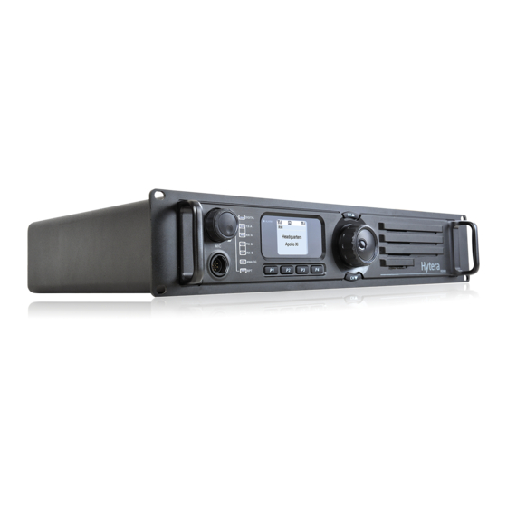
Page 99: Mobile Radio
Hytera DMR System Planner 3.2 Mobile Radio The mobile radio is designed to work in the vehicle and powered by the vehicle’s battery. It works at 13.6V ± 15% with negative end grounded. The product can operate in either analog or digital mode. Compared with the portable radio, the mobile radio extends the communication coverage. -
Page 100: Product Overview
Hytera DMR System Planner 3.2.1 Product Overview Front Panel 3.2.1-1 Front Panel Part Name Part Name Volume Control / Channel LED Indicator Selector Knob LCD Display OK/Menu Key Back Key Power On/Off Key Up Key Down Key Speaker Programmable Keys... - Page 101 Hytera DMR System Planner Rear Panel 3.2.1-2 Rear Panel Part Name Part Name RF Antenna Connector Power Inlet Accessory Jack GPS Antenna Connector Note: The GPS Antenna Connector is only available for some models. . Programmable Keys You can program the keys P1, P2, P3, P4,...
- Page 102 Hytera DMR System Planner Squelch Off To always unmute speaker no matter whether Squelch Off carrier is present or not Momentary To quickly return to the previous menu or home Home Screen screen Scan To receive signals on other channels...
-
Page 103: Basic Operations
Hytera DMR System Planner 3.2.2 Basic Operations Turning the Radio On/Off To turn the radio on, long press the Power On/Off key until the radio shows start-up screen and sounds an alert tone. Meanwhile, the LED flashes green. To turn the radio off, press the Power On/Off key. - Page 104 Hytera DMR System Planner Transmitting a call through Contact List or Call Logs Transmitting a call through Manual Dial Receiving and Responding to a Private Call After a Private Call is received, you may hold down the PTT key within the preset time period to call back.
- Page 105 Hytera DMR System Planner The LED indicator will help you easily identify the current radio status as described below. LED Indication Radio Status LED flashes green. Powering on LED glows red. Transmitting LED glows green. Receiving LED flashes orange slowly.
- Page 106 Hytera DMR System Planner interface for palm microphone (the Microphone Jack), with which users can perform operations such as call. Programmable Features (via Accessory Jack) For the mobile radio, you can program PIN3, PIN5, PIN6, PIN12, PIN20, PIN22 and PIN23 with features below:...
-
Page 107: Repeater
DMR digital repeater can work in analog mode. Hytera digital repeater can be configured via CPS; what’s more, to keep maintenance, it can be remotely configured via the RDAC. With this feature, the repeater used in remote areas, like forests or mountains can be easily monitored and configured, which enhances the work effectiveness. -
Page 108: Introduction
Hytera DMR System Planner 3.3.1 Introduction Front Panel The front panel Part Name Part Name Volume Control Knob/Power Accessory Jack Indicator Repeater Mode Indicator Analog Mode Indicator Slot 2 RX Indicator Slot 2 TX Indicator Digital Mode Indicator Slot 1 TX Indicator... - Page 109 Hytera DMR System Planner Rear Panel The rear panel Part Name Part Name TX Antenna Connector Optional Interface 1 RX/Duplex Antenna Connector Optional Interface 2 Monitor/Tuning Interface Accessory Jack DC Power Inlet Ethernet Interface Ground Screw Programmable Keys The P1, P2, P3, P4 can be programmed as shortcut to the following functions:...
-
Page 110: Basic Operations
Hytera DMR System Planner 3.3.2 Basic Operations Powering On/Off Connect the repeater to a DC source to turn the repeater on. During power-up process, the Power Indicator glows green and the repeater shows the power-on screen. To turn the repeater off, disconnect it from the DC source. - Page 111 The repeater is operating in Analog mode Digital Mode Indicator glows blue The repeater is operating in Digital mode Menu The customers can set and operate the terminal via menu. The menu of Hytera DMR repeater includes three 3 parts: Subscriber Parameters CH Information...
- Page 112 Hytera DMR System Planner External accessory jack In the rear part, the GPIO port uses a 26-pin board-to-board connector to connect with external device to get multiple features. The customers can program every pin port of the GPIO port. Apart from the 26-pin GPIO, a general network interface enables the customers to connect with the network to organize IP network.
- Page 113 Hytera DMR System Planner This function allows users to set which channel the Channel Steering 1-4 radio will switch to operate on. If an active level is detected, the Monitor feature will be Monitor Button enabled to unmute the speaker.
-
Page 114: Rdac (Repeater Diagnostics And Control)
Windows XP, Windows vista and Window 7 series 32-bit. RDAC is designed to by Hytera remotely diagnose and control the repeater. With RDAC, the repeater can work in normal state longer, and when any problem occurs, immediate maintenance will be carried out. -
Page 115: Diagnose
Hytera DMR System Planner 3.4.1 Diagnose RDAC can remotely supervise the operation state of the repeater. Once accidental event occurs, it will take measure immediately to ensure the repeater can work longer. Items would be diagnosed: PSU Voltage Monitor the voltage and alarm voltage in real time. -
Page 116: Control
Hytera DMR System Planner 3.4.2 Control RDAC can control the operation mode and state of the repeater. Restart the repeater Input the modified parameters. The following parameters can be modified. Current channel The TX power The state of repeater: to enable or disable the repeater Knockdown: to enable or disable the retransmitting function. -
Page 117: Repeater Configuration
Hytera DMR System Planner 3.4.3 Repeater Configuration To get normal communications, you can configure following parameters via RDAC to set the repeater in good performance. Basic setting: Powering on Designated power-up zone/channel Designate power-on channel Designate power-on zone Audio Priority... - Page 118 Hytera DMR System Planner Digital channel setting: Color Code Configure the channel color code (range: 1-15). IP Multi-site Connect Configure whether to retransmit the signal via IP network and specify a time slot. RX Frequency Configure the RX frequency. TX Frequency Configure the TX frequency.
- Page 119 Hytera DMR System Planner Transmitting Set the TX frequency. Set TX CTCSS/CDCSS type. Set CTCSS. Set CDCSS code Mixed channel setting: Channel Spacing Configure the bandwidth of the TX frequency and RX frequency. Carrier Squelch Level For better communications, you can set the squelch level of the repeater.
- Page 120 Hytera DMR System Planner Set CDCSS code Service setting: Group call hang time Set the duration the radio stays at in_call status after a group call transmission. You can call back the group directly without contact list selection. Private Call Hang Time Set the duration the radio stays at in_call status after a private call transmission.
-
Page 121: Dmr System Topologies
4 DMR System Topologies This section is intended to introduce the working mode and various application solutions. -
Page 122: Direct Mode
Hytera DMR System Planner 4.1 Direct Mode In direct mode, any radio can directly communicate with all of the other radios in the system within the communication coverage area. A Direct Mode system only requires radios for transmission and reception. As the TX power of the radio is low, its communication coverage distance is relatively short in direct mode. -
Page 123: Back-To-Back Mobile Radio Application In Direct Mode
Hytera DMR System Planner 4.1.1 Back-to-Back Mobile Radio Application in Direct Mode The “back-to-back” is a system solution on accessory pins. It is used to achieve cross-band communication among analog and digital radios. The back-to-back function realizes communication between analog and digital mobile radios. - Page 124 Hytera DMR System Planner 4.1.1.1 Back-to-Back Mobile Radio Connection The mobile radios can be connected in a back-to-back manner as below (Figure 2.15-2): Figure 4.1.1-2 Back-to-Back Mobile Radio Connection 1) Ground wire Connect Pin2 of mobile radio1 to that of mobile radio 2.
- Page 125 Hytera DMR System Planner encode the received audio data and transmit it as the digital signal. Thus the digital radios within the communication coverage area can receive the call. On the other hand, the analog mobile radio can transmit the received analog audio data to other mobile radios at other frequencies via the accessory pins, and then trigger the PTT of the analog mobile radio to transmit this analog signal.
- Page 126 Hytera DMR System Planner Figure 1-4 Analog-to-digital Conversion 2...
-
Page 127: Further Development Functions In Direct Mode
Hytera DMR System Planner 4.1.2 Further Development Functions in Direct Mode The mobile radio has available interface for further development in direct mode. Currently, the data services developed by the third party include GPS, text message, telemetry, radio control, data transmission and radio registration. The mobile radio can communicate with the computer via the USB port, and exchange data with other radios via the air interface. -
Page 128: Telemetry
Hytera DMR System Planner 4.1.3 Telemetry In direct mode, Telemetry is a function, which allows you to stay in control of your device remotely. To send the telemetry command properly, it shall satisfy these conditions: both TX and RX frequencies are consistent, the color codes are identical, and the radio is programmed properly. - Page 129 Hytera DMR System Planner 2) Controlling a remote equipment Controlling a remote device Source radio: 1) Send the control command to a radio or a group of radios. This command can cause the specified GPIO Pin to output active/inactive voltage, to toggle the voltage or to output pulse, enabling you to control the remote device.
- Page 130 Hytera DMR System Planner 3) Uploading the status of telemetry device Uploading the status of remote telemetry device Source radio: 1) Change in telemetry equipment status would cause the terminal GPIO status to change, which will trigger the source radio to upload its GPIO status.
-
Page 131: Repeater Mode
Hytera DMR System Planner 4.2 Repeater Mode The repeater mode means that the repeater is adopted during communication to extend the coverage area, due to geographical limitations such as mountains or man made obstructions. As for the digital repeater, an outstanding advantage is to detect and correct the error on the uplink during encoding and decoding, in order to ensure more accurate signal transmitted to the downlink. -
Page 132: Back-To-Back Repeaters
Hytera DMR System Planner In repeater mode, the following applications are available: Back-to-Back repeater application Dispatch Telemetry Phone application 4.2.1 Back-to-back Repeaters The back-to-back function realizes communication between analog and digital terminals. It works as below: 1) When the portable radio R1 transmits, the repeater 1 will retransmit the signals from R1 to the portable radio R2 and R3. - Page 133 Hytera DMR System Planner 4.2.1.1 Repeater Connection You can connect two repeaters using the accessory pin cable. The following sections give a general description on connection method. For any customized or expansion design, the method may vary. Analog-Digital Repeaters Figure 4.2.1.1-1: Connecting Analog-Digital Repeaters 1) Ground wire To connect PIN2 of analog repeater and that of digital repeater.
- Page 134 Hytera DMR System Planner Analog-Analog Repeaters Figure 4.2.1.1-2: Connecting Analog-Analog Repeaters 1) Ground wire To connect PIN2 of analog repeater 1 and that of analog repeater 2. 2) Activation of repeater transmission To connect PIN3 of analog repeater 1 and PIN16 of analog repeater 2.
- Page 135 Hytera DMR System Planner To connect PIN3 of digital repeater 1 and PIN16 of digital repeater 2. To connect PIN16 of digital repeater 1 and PIN3 of digital repeater 2. 3) Digital audio output To connect PIN24 or PIN25 of digital repeater 1 and PIN7 of digital repeater 2.
- Page 136 Hytera DMR System Planner Figure 4.2.1.1-5: Communication among Analog-Analog Repeaters 2 Communication among Analog-Digital Repeaters Figure 4.2.1.1-6: Communication among Analog-Digital Repeaters 1...
-
Page 137: Radio Dispatch
The RDS software developed by the third-party is tailed for dispatching, which is generally used in the Repeat mode. It can dispatch other terminals through the dispatch station. The SmartDispatch provided by Hytera is a PC-based intelligent dispatching application, which can meet your dispatching requirements. - Page 138 Hytera DMR System Planner Figure 4.2.3-1: Application of telemetry in Repeat mode The figure above shows three kinds of telemetry features: 1) Querying the status of remote telemetry device. The source terminal and the target terminal share the same frequency, and use the same slot (slot1) to transmit or and receive.
-
Page 139: Ip Multi-Site
TCP/IP-based network. In IP Multi-site Connect mode, DMR protocol is transported by TCP/IP protocol and a Hytera-owned protocol at Application Layer. Accordingly, it is reasonable to conclude that this mode only changes the DMR transmission media without affecting the services of DMR terminals. - Page 140 Hytera DMR System Planner For example, you can deploy multiple repeaters in a large building to ensure seamless communication. This can help fight the problems from unfavorable terrains. 3) To broadcast a message to all connected repeaters. For example, the dispatcher can send an instruction to all repeaters in IP Multi-site Connect mode in case of an emergency.
-
Page 141: Network Topology Of Ip Multi-Site Connect
Hytera DMR System Planner 4.3.1 Network Topology of IP Multi-site Connect The network topology of IP Multi-site Connect can operate with many networks or can connect all Wide Area Channels (WACH) via a physical network, depending upon the repeater location and the network connection. Typically, there are two... -
Page 142: Wide Area Network (Wan)
Hytera DMR System Planner IP Multi-site Connect Device Network IP Multi-site IP Multi-site Connect Device Connect Device IP Multi-site IP Multi-site Connect Device Connect Device IP Multi-site Connect Device Figure 4.3.2-1: IP Multi-site Connect Network Operating with LAN 4.3.3 Wide Area Network (WAN) - Page 143 Hytera DMR System Planner of bandwidth and time delay required by related devices. In addition, a sound understanding of bandwidth and time delay between two sites is also required, especially between two distant sites. In general, the time delay of satellite access across 5 continents is unacceptable, whereas this problem does not exist with cable communication.
-
Page 144: Wan And Lan
Hytera DMR System Planner 4.3.4 WAN and LAN Generally, WAN and LAN together constitute the network topology, for example, multiple remote sites or the LAN of two sites can be connected via an ISP. For WAN, its required bandwidth is related to the number of network devices in IP Multi-site Connect system, that is, the value shall be the sum of required bandwidth of each network device;... -
Page 145: Broadband Wireless Access
Hytera DMR System Planner IP Multi-site Connect Device Network Router IP Multi-site IP Multi-site Connect Device Connect Device 广域网 Router Router IP Multi-site IP Multi-site Connect Device Connect Device Router IP Multi-site Connect Device Figure 4.3.4-1: IP Multi-site Connect Network System Operating with WAN and LAN Note: the number of IP devices has an impact on the bandwidth requirement of WAN. - Page 146 Hytera DMR System Planner 4.3.5.1 Point-to-Point (PTP) and Ethernet Cable Figure 4.3.5.1-1: By Point-to-Point (PTP) and Ethernet Cable 4.3.5.2 Point-to-Point (PTP) and Local Area Network (LAN) Figure 4.3.5.2-1: By Point-to-Point (PTP) and Local Area Network (LAN)
- Page 147 Hytera DMR System Planner 4.3.5.3 Point-to-Point (PTP) Cluster and Local Area Network (LAN) Figure 4.3.5.3-1: By Point-to-Point (PTP) Cluster and Local Area Network (LAN) 4.3.5.4 Point-to-Point (PTP) and Wide Area Network (WAN) Figure 4.3.5.4-1:By Point-to-Point (PTP) and Wide Area Network (WAN)
- Page 148 Hytera DMR System Planner 4.3.5.5 Point-to-Multipoint (PMP) and Wide Area Network (WAN) Figure 4.3.5.5-1: By Point-to-Multipoint (PMP) and Wide Area Network (WAN) 4.3.5.6 Point-to-Multipoint (PMP) Cluster and Local Area Network (LAN) Figure 4.3.5.6-1: Point-to-Multipoint (PMP) Cluster and Local Area Network (LAN)
- Page 149 Hytera DMR System Planner 4.3.5.7 Point-to-Multipoint (PMP) Cluster and Wide Area Network (WAN) Figure 4.3.5.7-1: Point-to- Multipoint (PMP) Cluster and Wide Area Network (WAN)
-
Page 150: Digital Functions Supported In Ip Multi-Site Connect Mode
Hytera DMR System Planner 4.3.6 Digital Functions Supported in IP Multi-site Connect Mode Terminals (portable radio and mobile radio) are capable of providing a set of digital services (R3.0) in IP Multi-site Connect mode, as the following table shows. Functions... -
Page 151: Access Management
Hytera DMR System Planner 4.4 Access Management The Access Management is designed for the conventional communication system. It has two management types: Local Access Management and Multi-site Access Management. The former is to prevent the radio beyond the ID range from accessing the repeater, while the latter is to repeat the right data to the radio satisfying the predefined conditions over IP network. -
Page 152: Local Access Management
Hytera DMR System Planner 4.4.1 Local Access Management The Local Access Management feature is applicable to a local repeater. It ensures that access is granted to a radio whose ID is within the ID range only. See Figure as below: Figure 4.4.1-1: Local Access Management Example... -
Page 153: Multi-Site Access Management
Hytera DMR System Planner 4.4.2 Multi-site Access Management The Multi-site Access Management feature is used to repeat the satisfied data to the designated radio over IP Multi-site Connect. See Figure as below: Figure 4.4.2-1: Multi-site Access Management Example From above diagram, when both MS2 and MS3 make a private call (ID401) respectively, this call request will be transmitted to all repeaters in the system over IP Multi-site Connect. - Page 154 Hytera DMR System Planner Figure 4.4.2-2: Multi-site Access Management Example From above diagram, when MS1 makes a private call (ID301) to MS4, this call request will be transmitted to all repeaters in the system over IP Multi-site Connect. But only the repeater (BS4) will repeat it. That is because this private call ID is within the private call ID range of this repeater.
- Page 155 Hytera DMR System Planner Figure 4.4.2-3: Multi-site Access Management Example From above diagram, when MS1 makes a private call (ID301) to MS4, this call request will be transmitted to all repeaters in the system over IP Multi-site Connect. But only the repeater (BS4) will repeat it. That is because this private call ID is within the private call ID range of this repeater.
-
Page 156: Repeat Request Priority
When it receives both at the same time, which shall it transfer first? To solve this problem, Hytera DMR provides the Multi-site Priority feature, so you can define the priority to the signals or data to be transferred by the repeater. -
Page 157: Star Network Architecture
Hytera DMR System Planner 4.6.1 Star Network Architecture In this network, any Master Repeater can work as a Super Master, resulting in multiple Super Masters available. Figure 4.6.1-1: Super Master in the Star Network From the above diagram, when the Master Repeater A enables the Super Master... -
Page 158: Double-Layer Network Architecture
Hytera DMR System Planner 4.6.2 Double-layer Network Architecture In this network, there is only one Super Master available. Figure 4.6.2-1: Super Master in the Double-layer Network From the above diagram, you can see that the Master Repeater A works as a Super Master and has three Slave Repeaters including Master Repeater B, Master Repeater C and Master Repeater D. -
Page 159: Phone Interconnect
Hytera DMR System Planner 4.7 Phone Interconnect On the basis of the existing PSTN system, the Phone feature can enable communication between the mobile terminal and the phone by either connecting the local PSTN gateway via the repeater and then the phone system, or using the remote PSTN gateway via the IP Multi-site Connect feature. - Page 160 Hytera DMR System Planner Dial the phone number. Methods available for dialing the required phone number: Dial the phone number manually via the Live Dial or Buffer Dial method. Select a phone number from the Phone List and dial it.
- Page 161 Hytera DMR System Planner 4.7.1.2 Call from Phone to Terminal Figure 4.7.1.2-1: Call from Phone to Terminal Call process: 1. The phone dials a preset number. The terminal receives a call from the repeater, and hears an alert indicating the phone is waiting to be answered.
-
Page 162: Phone Applications In Ip Multi-Site Connect Mode
Hytera DMR System Planner 4.7.2 Phone Applications in IP Multi-site Connect Mode The Phone feature can be used in the IP Multi-site Connect mode. See Figure below: Figure 4.7.2-1: Call from Terminal to Phone in IP Multi-site Connect Mode Figure 47.2-2: Call from Phone to Terminal in IP Multi-site Connect Mode The procedures and process for using the Phone feature are the same in the IP Multi-site Connect mode and the local mode. -
Page 163: Dmr System Considerations
5 DMR System Considerations This chapter introduces the System software version Compatible and function interaction. 5.1 Important notes of R4.0 update 5.1.1 Subscriber 1. Please note that the SELP version of R3.5 and R4.0 software are not interoperable. As such, it is recommended to have all the system (subscriber and repeaters) upgraded to the same release if interoperability is required as only same versions of the vocoder is able to encode/decode the voice correctly. -
Page 164: Interaction Between Subscriber And Repeater
Hytera DMR System Planner 5.1.3 Interaction between Subscriber and Repeater 1. Please note that to achieve better call performance under interference, R4.0 subscriber shall only be used with R4.0 repeater. Note that R4.0 subscriber will not perform optimally with R3.5 repeater. However, using a R3.5 subscriber will be able to work properly with a R4.0 repeater. -
Page 165: Function Interaction
Hytera DMR System Planner 5.3 Function interaction 5.3.1 Phone Interconnect To use the Phone feature, you need to enable it for the terminal in the CPS and set appropriate Access Code and De-Access Code. To call the phone, please send the Access Code to access the phone system first. -
Page 166: Encryption
5.3.2 Encryption Can both encryption mechanisms apply to one terminal? Yes, but each channel supports one mechanism only.Hytera. Hytera provide three options: 40 bits, 128 bits and 256 bits. Will encryption affect the communication coverage and voice quality? No at all. -
Page 167: Priority Interrupt
Hytera DMR System Planner 5.3.4 Priority Interrupt Pseudo Trunk is a bi-slotted work mode allowing the subscriber to work in two slots, while Priority Interrupt is a function only working in Pseudo Trunk mode. The interrupting subscriber can only use one slot to transmit the voice signals, leading to the misunderstanding that Pseudo Trunk cannot support bi-slotted work mode with Priority Interrupt. - Page 168 Hytera DMR System Planner Interaction with the repeater: Priority Interrupt is supported within Call Hold of the repeater. If the repeater is transferring voice signals or term and detects Priority Interrupt data in the other slot, Call Hold in the Tx slot of the repeater will be interrupted, and the repeater will enter channel hold time and send information to the channel that it is free.
-
Page 169: Roaming
Hytera DMR System Planner 5.3.5 Roaming The Roaming and Scan features can not be set for the same channel. The Scan feature is mainly used in direct mode or Repeater mode to scan channels in the scan list, while the Roaming feature is mainly used in the IP Multi-site Connect network to scan channels in the Roam list. -
Page 170: Ip Multi-Site Connect
Hytera DMR System Planner 5.3.6 IP Multi-site Connect How to select frequency and color code in IP Multi-site Connect network? You can select the proper networking scheme as per your actual needs. In the overlapping area, it is recommended that the frequency of the repeater be different, but the color code can be the same or varied. - Page 171 Hytera DMR System Planner The network establishment and configuration are determined by the devices and IP network. You’d better get help from the network administrator due to the complicate networking environments. Some common factors are listed below: 1) Ensure that there is no conflicting IP address, which can break off communication.
- Page 172 16 in R3.0 to 22 in R3.5! Please note that the Hytera RND team is still optimizing the slave amount and is continually researching to increase the slave amount to be close to 30, promising more delighters to customer upcoming.
-
Page 173: Telemetry
Hytera DMR System Planner In IP Multi-site Connect mode, the repeater will add a silent frame as compensation to the voice or data packet lost during transmission. Accordingly, the communication with a terminal will be discontinuous. In case two voice and data packets are lost consecutively, the repeater will judge the call as abnormal and abort it automatically. - Page 174 Hytera DMR System Planner For your notes...
-
Page 175: Dmr System Documentation And Applications
6 DMR System Documentation and Applications This document introduces a list of documentation provided by Hytera to help you better understand the product. It also describes the standard applications for servicing radios. 6.1 Documentation Currently, Hytear can provide the following documents:... -
Page 176: Cps
Hytera DMR System Planner HDAP ADK Hytera DMR ADK Development Guide R1.00 Hytera DMR Application Programming Interface R1.00 Hytera DMR Application Protocol Specification R1.00 Hytera DMR ADK Overview R1.00 You can visit our website to download the above documents, or contact us or your local dealer to obtain them. -
Page 177: Tuner
Hytera DMR System Planner 2. Shortcuts: It provides the useful shortcuts for actions you perform frequently. When you move the cursor over an icon, its function will be displayed. 3. Tab Name: When you open a tab, the corresponding tab name will appear. When you open multiple tabs, you can directly click one tab to access the configuration interface. - Page 178 Hytera DMR System Planner For your notes...
-
Page 179: Appendix
Data Operated Squelch Data Delivery Service Digital Mobile Radio Data Transmit Protocol Geography Information System GPIO General Purpose Input/Output Global Position System HDAP Hytera DMR Application Protocol HRNP Hytera Radio Network Protocol Location Protocol Internet Protocol Microphone Application Partnership Program... -
Page 180: Hytera Official Website
Real-time Transport Protocol Telemetry Protocol Text Message Protocol UART Universal Asynchronous Receiver/Transmitter User Datagram Protocol Universal Serial Bus A.2 Hytera Official Website You can make an order or obtain product information by visiting our official website at: http://www.hytera.com, or contacting your dealer.
Need help?
Do you have a question about the PD78X Series and is the answer not in the manual?
Questions and answers