FLIR K Series User Manual
Hide thumbs
Also See for K Series:
- Getting started (122 pages) ,
- Getting started manual (74 pages) ,
- Notice to end users (4 pages)
Table of Contents
Advertisement
Advertisement
Table of Contents

Related Manuals for FLIR K Series


Summary of Contents for FLIR K Series
- Page 1 User’s manual Flir K series...
- Page 2 User’s manual Flir K series #T559811; r. AE/ 9082/9150; en-US...
-
Page 3: Table Of Contents
Customer help ..................6 General .................. 6 Submitting a question ..............6 Downloads ................6 Important information about Flir K series service ........7 What is the Flir K series? ..............8 Quick start guide ................9 Parts lists ..................10 Scope of delivery ..............10 List of accessories and services.......... - Page 4 14.1.3 Procedure ..............27 14.2 Infrared lens ................27 14.2.1 Liquids............... 27 14.2.2 Equipment ..............27 14.2.3 Procedure ..............27 About Flir Systems ................28 15.1 More than just an infrared camera ..........29 15.2 Sharing our knowledge ............29 15.3 Supporting our customers............
-
Page 5: Legal Disclaimer
The purchaser ZL201030595931.3; ZL201130442354.9; ZL201230471744.3; shall promptly report any defect to Flir Systems or this warranty will not apply. ZL201230620731.8 Flir Systems will, at its option, repair or replace any such defective product free of charge if, upon inspection, it proves to be defective in material or work- 1.8 EULA Terms... -
Page 6: Warnings & Cautions
Applicability: Cameras with one or more batteries. Do not attach the batteries directly to a car’s cigarette lighter socket, unless Flir Systems supplies a spe- cific adapter to connect the batteries to a cigarette lighter socket. Damage to the batteries can occur. - Page 7 Warnings & Cautions CAUTION Applicability: Cameras with one or more batteries. Do not make holes in the battery with objects. Damage to the battery can occur. CAUTION Applicability: Cameras with one or more batteries. Do not hit the battery with a hammer. Damage to the battery can occur. CAUTION Applicability: Cameras with one or more batteries.
- Page 8 CAUTION Do not use the Flir K series camera without the correct training. If the persons that operate the camera do not have the correct training, an incorrect analysis of the infrared images can occur. Thus, incorrect decisions during the firefighting can be made.
-
Page 9: Notice To User
3.7 Important note about this manual Flir Systems issues generic manuals that cover several cameras within a model line. This means that this manual may contain descriptions and explanations that do not apply to your particular camera model. -
Page 10: Customer Help
• The communication protocol, or method, between the camera and your device (for ex- ample, HDMI, Ethernet, USB, or FireWire) • Device type (PC/Mac/iPhone/iPad/Android device, etc.) • Version of any programs from Flir Systems • Full name, publication number, and revision number of the manual 4.3 Downloads On the customer help site you can also download the following: •... -
Page 11: Important Information About Flir K Series Service
• Flir Systems reserves the right to charge the full cost for the decontamination of con- taminated cameras that are shipped to our service department. -
Page 12: What Is The Flir K Series
• Easy-to-use, and in a gloved firefighter’s hand. An intuitive and simple user inter- face allows you to focus on the job. The Flir K series can be controlled by just three large buttons on top of the unit and one trigger. Ideal for a gloved firefighter’s hand. -
Page 13: Quick Start Guide
Moving an image using a drag-and-drop operation does not delete the image in the camera. • Move the image to the computer using Flir Tools. A download card for Flir Tools is included in the transport case. In Flir Tools you can analyze the images and create PDF reports. -
Page 14: Parts Lists
• USB cable. • User documentation CD-ROM. Note FLIR Systems reserves the right to discontinue models, parts or accessories, and other items, or to change specifications at any time without prior notice. 8.2 List of accessories and services • 1910423 USB cable Std A to Mini-B. -
Page 15: System Parts
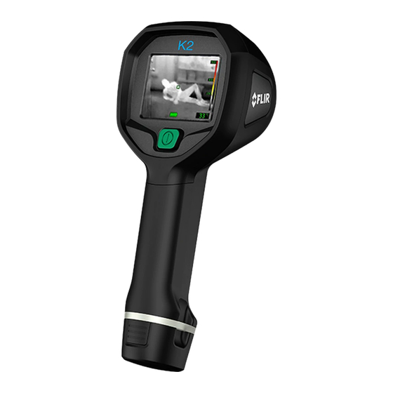
9.1 Camera 9.1.1 Figure 9.1.2 Explanation 1. USB Mini-B connector: Connect to a computer to download images using Flir Tools. 2. Attachment point for lanyard strap/neck strap (left and right side). 3. Eccentric latch to secure the battery. 4. On/off button. This button has two functions: •... -
Page 16: Lanyard Strap + Retractable Lanyard
System parts 9.2 Lanyard strap + retractable lanyard 9.2.1 Figure 9.2.2 Explanation The lanyard strap is attached at position 2 on the camera (see section 9.1 Camera, page 11). The retractable lanyard is then connected to the lanyard strap. 9.3 Neck strap 9.3.1 Figure 9.3.2 Explanation The neck strap is attached at position 2 on the camera (see section 9.1 Camera, page... -
Page 17: Screen Elements
Screen elements 10.1 Figure 10.2 Explanation 1. Heat detection mode. Optimized for searching hotspots during overhaul after the fire is out. 2. Search and rescue mode. Optimized for maintaining high contrast in the infrared im- age while searching for people. 3. -
Page 18: Operation
Operation 11.1 Removing the battery 11.1.1 Procedure Follow this procedure: 1. Pull the eccentric latch. 2. Pull out the battery from the battery compartment. 11.2 Charging the battery 11.2.1 General Charge the battery for 4 hours before starting the camera for the first time, or until the blue battery condition LED glows continuously. -
Page 19: Selecting Camera Modes
Operation 11.3 Selecting camera modes 11.3.1 General The Flir K series features five different camera modes. You select camera mode by push- ing the Mode button. The five different camera modes are: 1. NFPA firefighting mode. (NFPA = National Fire Protection Association, an internation- al non-profit organization. - Page 20 Operation 11.3.2.2 Black and white firefighting mode Figure 11.2 Black and white firefighting mode. The black and white firefighting mode is an NFPA standardized firefighting mode. It is a multipurpose mode for the initial fire attack with life rescuing operation and control of the fire.
- Page 21 Operation 11.3.2.4 Search and rescue mode Figure 11.4 Search and rescue mode. The search and rescue mode is optimized for maintaining high contrast in the infrared image while searching for people in landscapes, buildings, or traffic accident scenes. • High sensitivity range only. •...
-
Page 22: Saving An Image
Operation 11.4 Saving an image 11.4.1 General You can save images to the camera’s image archive. Note The maximum number of images that can be saved in the image archive is 200. When the number of images exceed 200, images are deleted on a first-in, first-out basis, i.e., the 201st image will delete the 1st image, the 202nd image will delete the 2nd image, and so on. -
Page 23: Connecting The Camera To A Computer
You can connect the camera to a computer, using the USB cable. Once connected, you can move the images from the camera’s image archive to the computer. You can also im- port the images into our Flir Tools software. A download card for Flir Tools is included in the transport case. - Page 24 • Move the images to the computer using a drag-and-drop operation. Note Moving an image using a drag-and-drop operation does not delete the image in the camera. • Move the images to the computer using Flir Tools. #T559811; r. AE/ 9082/9150; en-US...
-
Page 25: Viewing Saved Images
Operation 11.6 Viewing saved images 11.6.1 General When you save an image, the image is stored in the camera’s image archive. To display the image again, you can recall it from the archive. 11.6.2 Procedure Follow this procedure: 1. Push and hold the Mode button, then push the Zoom button. This will display the screen below. -
Page 26: Changing Settings
Operation 11.7 Changing settings 11.7.1 General You can change a variety of settings. These settings include the following: • Temperature unit. • Temperature indication. • Date. • Time. • Factory default settings. 11.7.2 Procedure Follow this procedure: 1. Push and hold the Mode button, then push the Zoom button. This will display the screen below. -
Page 27: In-Truck Charger (Optional Accessory)
12.1 Introduction Thank you for choosing the Flir K series in-truck charger from Flir Systems. The in-truck charger is intended to be mounted on a flat surface in the cab, in one of the equipment lockers, or in another suitable compartment on the fire engine. The in-truck charger has five ports for cable routing—one through the rear of the metal bracket and... -
Page 28: Choosing A Suitable Position
In-truck charger (optional accessory) 4. Connectors in the cradle. 5. Connector to power the charger using a standard Flir Systems power supply. 6. Hole for attaching the charger housing to the metal bracket. 7. LED indicator for the battery charger. -
Page 29: Charging A Battery Separately
In-truck charger (optional accessory) 12.7 Charging a battery separately Flir K series batteries can be charged separately using the battery charger at the lower front of the unit. Follow this procedure: 1. Pull the eccentric latch on the bottom of the camera. -
Page 30: Technical Data
For technical data on this product, refer to the product catalog and/or technical data- sheets on the User Documentation CD-ROM that comes with the product. The product catalog and the datasheets are also available at http://support.flir.com. #T559811; r. AE/ 9082/9150; en-US... -
Page 31: Cleaning The Camera
Cleaning the camera 14.1 Camera housing, cables, and other items 14.1.1 Liquids Use one of these liquids: • Warm water • A weak detergent solution 14.1.2 Equipment A soft cloth 14.1.3 Procedure Follow this procedure: 1. Soak the cloth in the liquid. 2. -
Page 32: About Flir Systems
—together with a worldwide network of agents and distributors—support our internation- al customer base. Flir Systems is at the forefront of innovation in the infrared camera industry. We anticipate market demand by constantly improving our existing cameras and developing new ones. -
Page 33: More Than Just An Infrared Camera
10 L (2.6 US gallon) jar with liquid nitrogen. To the left of the oscilloscope the Polaroid attachment (6 kg/13 lb.) can be seen. RIGHT: Flir i7 from 2012. Weight: 0.34 kg (0.75 lb.), including the battery. -
Page 34: A Few Images From Our Facilities
About Flir Systems 15.4 A few images from our facilities Figure 15.3 LEFT: Development of system electronics; RIGHT: Testing of an FPA detector Figure 15.4 LEFT: Diamond turning machine; RIGHT: Lens polishing Figure 15.5 LEFT: Testing of infrared cameras in the climatic chamber; RIGHT: Robot used for camera testing and calibration #T559811;... -
Page 35: History Of Infrared Technology
History of infrared technology Before the year 1800, the existence of the infrared portion of the electromagnetic spec- trum wasn't even suspected. The original significance of the infrared spectrum, or simply ‘the infrared’ as it is often called, as a form of heat radiation is perhaps less obvious to- day than it was at the time of its discovery by Herschel in 1800. - Page 36 History of infrared technology When Herschel revealed his discovery, he referred to this new portion of the electromag- netic spectrum as the ‘thermometrical spectrum’. The radiation itself he sometimes re- ferred to as ‘dark heat’, or simply ‘the invisible rays’. Ironically, and contrary to popular opinion, it wasn't Herschel who originated the term ‘infrared’.
- Page 37 History of infrared technology Figure 16.4 Samuel P. Langley (1834–1906) The improvement of infrared-detector sensitivity progressed slowly. Another major break- through, made by Langley in 1880, was the invention of the bolometer. This consisted of a thin blackened strip of platinum connected in one arm of a Wheatstone bridge circuit upon which the infrared radiation was focused and to which a sensitive galvanometer re- sponded.
- Page 38 A note on the technical production of this publication This publication was produced using XML — the eXtensible Markup Language. For more information about XML, please visit http://www.w3.org/XML/ A note on the typeface used in this publication This publication was typeset using Linotype Helvetica™ World. Helvetica™ was designed by Max Miedinger (1910–1980) LOEF (List Of Effective Files) T501016.xml;...
- Page 39 F o r mo r e i n f o r ma t i o n c o n t a c t : 6 6 2 0 Or c h i d L a k e R d . N e w P o r t R i c h e y , F L . 3 4 6 5 5 - 1 1 1 1 ( 7 2 7 ) 8 4 8 - 2 4 2 4 - ( 8 0 0 ) 3 6 7 - 9 0 5 4 - f a x ( 7 2 7 ) 8 4 5 - 5 9 4 1 www.
Need help?
Do you have a question about the K Series and is the answer not in the manual?
Questions and answers