Table of Contents
Advertisement
Advertisement
Table of Contents

Related Manuals for FLIR K33


Summary of Contents for FLIR K33
- Page 1 User’s manual FLIR Kx3 series...
- Page 3 User’s manual FLIR Kx3 series #T810170; r. AE/41948/41948; en-US...
-
Page 5: Table Of Contents
Customer help ..................8 General ..................8 Submitting a question ..............8 Downloads ................9 Important information about FLIR Kx3 series service......10 Quick start guide ................11 Quick start guide, FLIR K33 ............11 Quick start guide, FLIR K53 ............11 List of accessories and services ............ - Page 6 Table of contents 11.4.3 Procedure ..............22 11.5 Recording a video clip (FLIR K53) ..........22 11.5.1 General................ 22 11.5.2 Figure................22 11.5.3 Procedure ..............22 11.6 Continuous video recording (FLIR K53) ......... 23 11.6.1 General................ 23 11.7 Freezing the image..............23 11.7.1 General................
- Page 7 Table of contents 19.2 Sharing our knowledge .............. 56 19.3 Supporting our customers............56 History of infrared technology............. 57 #T810170; r. AE/41948/41948; en-US...
-
Page 9: Legal Disclaimer
FLIR Systems will, at its option, repair or replace any such defective product free of charge if, upon inspection, it proves to be defective in material or work- 1.8 EULA Terms manship and provided that it is returned to FLIR Systems within the said one- year period. •... -
Page 10: Safety Information
Applicability: Cameras with one or more batteries. Do not attach the batteries directly to a car’s cigarette lighter socket, unless FLIR Systems supplies a spe- cific adapter to connect the batteries to a cigarette lighter socket. Damage to the batteries can occur. - Page 11 Safety information CAUTION Applicability: Cameras with one or more batteries. Do not make holes in the battery with objects. Damage to the battery can occur. CAUTION Applicability: Cameras with one or more batteries. Do not hit the battery with a hammer. Damage to the battery can occur. CAUTION Applicability: Cameras with one or more batteries.
- Page 12 This includes the compartments for data storage, batteries, and connectors. CAUTION Do not change the standard fire-fighting procedures when you use a FLIR K series camera. The FLIR K series camera is not a replacement technology. #T810170; r. AE/41948/41948; en-US...
- Page 13 Safety information CAUTION Do not use the FLIR K series camera without the correct training. If the persons that operate the camera do not have the correct training, an incorrect analysis of the infrared images can occur. Thus, incorrect decisions during the firefighting can be made.
-
Page 14: Notice To User
3.5 Important note about this manual FLIR Systems issues generic manuals that cover several cameras within a model line. This means that this manual may contain descriptions and explanations that do not apply to your particular camera model. -
Page 15: Note About Authoritative Versions
Notice to user 3.6 Note about authoritative versions The authoritative version of this publication is English. In the event of divergences due to translation errors, the English text has precedence. Any late changes are first implemented in English. #T810170; r. AE/41948/41948; en-US... -
Page 16: Customer Help
Customer help 4.1 General For customer help, visit: http://support.flir.com 4.2 Submitting a question To submit a question to the customer help team, you must be a registered user. It only takes a few minutes to register online. If you only want to search the knowledgebase for existing questions and answers, you do not need to be a registered user. -
Page 17: Downloads
• The communication protocol, or method, between the camera and your device (for ex- ample, SD card reader, HDMI, Ethernet, USB, or FireWire) • Device type (PC/Mac/iPhone/iPad/Android device, etc.) • Version of any programs from FLIR Systems • Full name, publication number, and revision number of the manual 4.3 Downloads... -
Page 18: Important Information About Flir Kx3 Series Service
• FLIR Systems reserves the right to charge the full cost for the decontamination and dis- infection of contaminated cameras that are shipped to our service department. -
Page 19: Quick Start Guide
4. To freeze the image, pull and hold the trigger. 5. To return to the live image, release the trigger. Note The function of the trigger is configured by a setting in FLIR Tools, see section 11.10.2 The User interface tab, page 27. -
Page 20: List Of Accessories And Services
List of accessories and services Product name Part no. Battery charger, incl. power supply with multi plugs T198125 (Exx, Kxx) Battery Li-ion 3.6 V, 4.4 Ah, 16 Wh T199368ACC Carabiner strap T129915ACC Cigarette lighter adapter kit, 12 VDC, 1.2 m/3.9 ft. T198509 In-truck charger T198322ACC... -
Page 21: System Configuration Overview
System configuration overview 8.1 Figure 8.2 Explanation 1. FLIR P/N: 1910423, USB cable Std A <-> Mini-B 2. FLIR P/N: T127724ACC, Neck strap 1. The inclusion of this item is dependent on model. #T810170; r. AE/41948/41948; en-US... - Page 22 4. FLIR P/N: T198457ACC, Tripod Adapter, Kxx 5. FLIR P/N: T198125, Battery charger, incl. power supply with multi plugs 6. FLIR P/N: T198509, Cigarette lighter adapter kit, 12 VDC, 1.2 m/3.9 ft 7. FLIR P/N: T198310ACC, Li-Ion Battery pack 3.6 V 16 Wh 8.
-
Page 23: System Parts
9.1 Camera parts 9.1.1 Figure 9.1.2 Explanation 1. USB Mini-B connector: Connect to a computer to download images (FLIR K53 only) and change settings using FLIR Tools. 2. Attachment point for the lanyard strap/neck strap (left and right sides). 3. Eccentric latch to secure the battery. -
Page 24: Lanyard Strap And Retractable Lanyard
System parts 9.2 Lanyard strap and retractable lanyard 9.3 Handle strap and retractable lanyard #T810170; r. AE/41948/41948; en-US... -
Page 25: Neck Strap
System parts 9.4 Neck strap #T810170; r. AE/41948/41948; en-US... -
Page 26: Screen Elements
Screen elements 10.1 Figure 10.2 Explanation 1. Low-sensitivity mode indicator. The indicator is displayed when the camera identifies a hot area and automatically switches to the low-sensitivity mode. 2. Overheating indicator. The indicator provides a visual warning to the user that the ther- mal imager is about to shut down due to internal overheating. -
Page 27: Operation
Operation CAUTION Do not use the FLIR K series camera without the correct training. If the persons that operate the camera do not have the correct training, an incorrect analysis of the infrared images can occur. Thus, incorrect decisions during the firefighting can be made. -
Page 28: Turning On And Turning Off The Camera
Operation 11.1.1.1 General Charge the battery for 4 hours before starting the camera for the first time, or until the blue battery condition LED glows continuously. 11.1.1.2 Procedure Follow this procedure: 1. Put the battery in the standalone battery charger. 2. -
Page 29: Automatic Temperature Range Selection
11.3.1.3 Explanation 1. LCD area. 2. Area activating the automatic range change. 11.4 Saving an image (FLIR K53) 11.4.1 General You can save images to the camera’s archive. Note The maximum number of images that can be saved in the archive is 200. When the number of images exceeds 200, images are deleted on a first-in, first-out basis, i.e.,... -
Page 30: Figure
Operation 11.4.2 Figure 11.4.3 Procedure Note The function of the trigger is configured by a setting in FLIR Tools, see section 11.10.2 The User interface tab, page 27. Follow this procedure: 1. Aim the camera toward an object of interest. -
Page 31: Continuous Video Recording (Flir K53)
Follow this procedure: 1. Aim the camera toward an object of interest. 2. Depending on the Trigger button setting in FLIR Tools, do one of the following to start the recording: • With the Rec. on/off setting, pull the trigger. -
Page 32: Changing The Temperature Unit
• Change the camera settings using the FLIR Tools software. See section 11.10 Chang- ing settings in FLIR Tools, page 26. • Applicable to FLIR K53: Move the images and video clips from the camera’s archive to the computer. • Applicable to FLIR K53: Import the images into the FLIR Tools software. -
Page 33: Procedure
Operation 11.9.2 Procedure Follow this procedure: 1. Fold up the rubber cover at the top of the camera. 2. Hold the metal ring firmly. 3. Rotate the ring about 90° counter-clockwise. 4. Pull out the plastic insert. CAUTION The plastic insert has an O-ring seal. Do not damage the O-ring seal. 5. -
Page 34: Changing Settings In Flir Tools
Windows Explorer. Note Moving an image using a drag-and-drop operation does not delete the im- age in the camera. • Move the images to the computer using FLIR Tools. 11.10 Changing settings in FLIR Tools 11.10.1 The General settings tab 11.10.1.1 Figure... -
Page 35: The User Interface Tab
The recording will stop when you release the trigger. • Rec. on/off, No action (not applicable to the FLIR K33): Select to make the camera start a recording when you press the trigger and stop the recording when you press the trig- ger again. - Page 36 Operation Gain mode area: • Auto gain mode: Select to make the camera automatically switch between the high- sensitivity range and the low-sensitivity range, depending on the scene temperature. The temperature level at which the camera switches between the two modes is 150°C (302°F).
-
Page 37: In-Truck Charger (Optional Accessory)
The in-truck charger can also be powered using a standard FLIR Systems power supply, and has a battery charger located at the lower front of the unit. -
Page 38: Parts And Functions
3. Hole for attaching the charger housing to the metal bracket. 4. Connectors in the cradle. 5. Connector to power the charger using a standard FLIR Systems power supply. 6. Hole for attaching the charger housing to the metal bracket. -
Page 39: Recommended Cable Area And Fuse
The charging of the camera has now started, and is finished when the blue light glows continuously. Charging a fully depleted camera takes approximately 4 hours. 12.7 Charging a battery separately FLIR Kx3 series batteries can be charged separately using the battery charger at the lower front of the unit. Follow this procedure: 1. -
Page 40: Cleaning
The in-truck charger can be cleaned using warm water or a weak detergent solution. Do not use solvents or similar liquids. 12.9 Customer support Should you experience any problems, do not hesitate to contact our Customer Support at http://support.flir.com. #T810170; r. AE/41948/41948; en-US... -
Page 41: Technical Data
13.2 Note about technical data FLIR Systems reserves the right to change specifications at any time without prior notice. Please check http://support.flir.com for latest changes. -
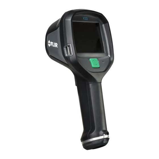
Page 42: Flir K33
Easy-to-use—also in a gloved firefighter’s hand: An intuitive and simple user interface allows you to fo- cus on the job. The FLIR K33 can be controlled by just one large button on top of the unit. Ideal for a gloved firefighter’s hand. - Page 43 Local adaptation of units, date and time formats Languages English Video streaming Non-radiometric IR video streaming Uncompressed colorized video using USB USB Mini-B Compatibility Compatible with FLIR software FLIR Tools Data communication interfaces Interfaces • Update from PC devices • Data transfer to and from PC...
- Page 44 Technical data Environmental data Humidity (operating and storage) IEC 60068-2-30/24 h 95% relative humidity +25°C to +40°C (+77°F to +104°F) / 2 cycles Relative humidity 95% relative humidity +25°C to +40°C (+77°F to +104°F) non-condensing Directives Designed to meet NFPA 1801:2013 specification: •...
- Page 45 Technical data Supplies & accessories: • 1910423; USB cable Std A <-> Mini-B • T198509; Cigarette lighter adapter kit, 12 VDC, 1.2 m/3.9 ft. • T198125; Battery charger, incl. power supply with multi plugs (Exx, Kxx) • T198310ACC; Li-Ion Battery pack 3.6 V 16 Wh •...
-
Page 46: Flir K53
Easy-to-use—also in a gloved firefighter’s hand: An intuitive and simple user interface allows you to fo- cus on the job. The FLIR K53 can be controlled by just one large button on top of the unit. Ideal for a gloved firefighter’s hand. - Page 47 IR only File formats Standard JPEG Image annotations Report generation Separate software (FLIR Tools) Video recording in camera Non-radiometric IR video recording MPEG-4 to internal flash memory Storage capacity 200 files in total, with a maximum duration of 5 mi- nutes each.
- Page 48 Technical data Power system Battery type Li Ion Battery voltage 3.6 V Battery capacity 4.4 Ah, at +20°C to +25°C (+68°F to +77°F) Battery operating time Approx. 4 hours at +25°C (+77°F) ambient temper- ature and typical use Charging system •...
- Page 49 Technical data Physical data Tripod mounting UNC ¼"-20 (adapter needed) Material • PPSU • Silicon rubber • Aluminium, cast • Flame-resistant magnesium alloy Shipping information List of contents • Infrared camera • Battery (2 ea.) • Battery charger • Hard transport case •...
-
Page 50: In-Truck Charger
Technical data 13.6 In-truck charger P/N: T198322 Rev.: 28825 Power system Charging time < 4 hours Charging temperature 0°C to +45°C (+32°F to +113°F) External power, connector type Screw terminal or HRS_UK60-3PT DC operation 12/ 24 V DCnominal (11.1 - 28.0 V DC) Power Max 36 Watts or 3000 mA at 12 VDC (5 amps fuse) - Page 51 Technical data Shipping information UPC-12 845188005368 Estonia Country of origin Compatible with the following products • 72201-0106; FLIR K45 • 72201-0206; FLIR K55 • 72202-0303; FLIR K65 #T810170; r. AE/41948/41948; en-US...
-
Page 52: Mechanical Drawings
Mechanical drawings [See next page] #T810170; r. AE/41948/41948; en-US... - Page 55 6,02 7,08 ±0,04 ±0,04 ±1 ±1 Mounting hole 10x ø5,0 Mounting hole 6x ø6,3 Konstr/Drawn Datum/Date Kontr/Check Material P. MARCUS 2013-04-08 MABR Ytjämnhet/Roughness Ytbehandling/Surface treatment Ändrad av/Modified by Ändrad/Modified P. MARCUS 2013-04-08 µm Skala/Scale Blad/Sheet Där ej annat anges/Unless otherwise stated Benämning/Denomination 1(1) ISO 2768-mK...
-
Page 56: Ce Declaration Of Conformity
CE Declaration of conformity [See next page] #T810170; r. AE/41948/41948; en-US... -
Page 58: Cleaning, Decontamination And Disinfection
Cleaning, decontamination and disinfection 16.1 Cleaning 16.1.1 Camera housing, cables, and other items 16.1.1.1 Liquids Use one of these liquids: • Warm water • A weak detergent solution 16.1.1.2 Equipment A soft cloth 16.1.1.3 Procedure Follow this procedure: 1. Soak the cloth in the liquid. 2. -
Page 59: Decontamination And Disinfection
• FLIR Systems reserves the right to charge the full cost for the decontamination and dis- infection of contaminated cameras that are shipped to our service department. -
Page 60: Maintenance, Inspection, And Service
5. Verify the function of all buttons and triggers. 6. Inspect the attachment point for the lanyard strap/neck strap, and the attachment point for the retractable lanyard. 17.3 Service For contact details to our service departments, use the following link: http://support.flir.com/service #T810170; r. AE/41948/41948; en-US... -
Page 61: Storage Conditions
Storage conditions The following storage conditions apply. Storage temperature range –40°C to +85°C (–40°F to +185°F) Storage humidity IEC 60068-2-30/24 h 95% relative humidity +25°C to +40°C (+77°F to +104°F) / 2 cycles #T810170; r. AE/41948/41948; en-US... -
Page 62: About Flir Systems
• Prox Dynamics (2016) Figure 19.1 Patent documents from the early 1960s FLIR Systems has three manufacturing plants in the United States (Portland, OR, Boston, MA, Santa Barbara, CA) and one in Sweden (Stockholm). Since 2007 there is also a... -
Page 63: More Than Just An Infrared Camera
19.1 More than just an infrared camera At FLIR Systems we recognize that our job is to go beyond just producing the best infrared camera systems. We are committed to enabling all users of our infrared camera systems to work more productively by providing them with the most powerful camera–software... -
Page 64: Sharing Our Knowledge
Although our cameras are designed to be very user-friendly, there is a lot more to thermog- raphy than just knowing how to handle a camera. Therefore, FLIR Systems has founded the Infrared Training Center (ITC), a separate business unit, that provides certified training courses. -
Page 65: History Of Infrared Technology
History of infrared technology Before the year 1800, the existence of the infrared portion of the electromagnetic spectrum wasn't even suspected. The original significance of the infrared spectrum, or simply ‘the in- frared’ as it is often called, as a form of heat radiation is perhaps less obvious today than it was at the time of its discovery by Herschel in 1800. - Page 66 History of infrared technology Moving the thermometer into the dark region beyond the red end of the spectrum, Her- schel confirmed that the heating continued to increase. The maximum point, when he found it, lay well beyond the red end – in what is known today as the ‘infrared wavelengths’. When Herschel revealed his discovery, he referred to this new portion of the electromag- netic spectrum as the ‘thermometrical spectrum’.
- Page 67 History of infrared technology Figure 20.4 Samuel P. Langley (1834–1906) The improvement of infrared-detector sensitivity progressed slowly. Another major break- through, made by Langley in 1880, was the invention of the bolometer. This consisted of a thin blackened strip of platinum connected in one arm of a Wheatstone bridge circuit upon which the infrared radiation was focused and to which a sensitive galvanometer re- sponded.
- Page 68 A note on the technical production of this publication This publication was produced using XML — the eXtensible Markup Language. For more information about XML, please visit http://www.w3.org/XML/ A note on the typeface used in this publication This publication was typeset using Linotype Helvetica™ World. Helvetica™ was designed by Max Miedinger (1910–1980) LOEF (List Of Effective Files) T501215.xml;...
- Page 70 Disclaimer Specifications subject to change without further notice. Models and accessories subject to regional market considerations. License procedures may apply. Products described herein may be subject to US Export Regulations. Please refer to exportquestions@flir.com with any questions. Publ. No.: T810170...
Need help?
Do you have a question about the K33 and is the answer not in the manual?
Questions and answers