Moxa Technologies NPort 5100 Series User Manual
Advanced, 1-port rs-232/422/485 serial device servers
Hide thumbs
Also See for NPort 5100 Series:
- Tech note (5 pages) ,
- Quick installation manual (2 pages) ,
- User manual (194 pages)
Table of Contents
Advertisement
Quick Links
Advertisement
Table of Contents

Related Manuals for Moxa Technologies NPort 5100 Series


Summary of Contents for Moxa Technologies NPort 5100 Series
- Page 2 NPort 5100 Series User’s Manual Second Edition, December 2007 www.siesamx.com www.moxa.com/product Moxa Inc. Tel: +886-2-8919-1230 Fax: +886-2-8919-1231 Web: www.moxa.com MOXA Technical Support Worldwide: support@moxa.com The Americas: support@usa.moxa.com...
-
Page 3: Copyright Notice
Information provided in this manual is intended to be accurate and reliable. However, MOXA Technologies assumes no responsibility for its use, or for any infringements on the rights of third parties that may result from its use. -
Page 4: Table Of Contents
Package Checklist ......................1-2 Product Features......................... 1-2 Product Specifications......................1-3 Chapter 2 Getting Started..................2-1 Panel Layout of NPort 5100 Series ..................2-2 Connecting the Hardware....................2-2 Connecting the Power ..................... 2-2 Connecting to the Network ..................2-3 Connecting to a Serial Device................. 2-3 LED Indicators...................... - Page 5 Auto Warning Settings ..................... 5-29 Auto warning: Email and SNMP trap ..............5-29 Event Type ......................5-30 Monitor..........................5-31 Monitor Line ......................5-31 Monitor Async ...................... 5-32 Monitor Async-Settings ..................5-32 Change Password ......................5-32 Load Factory Default ....................... 5-33 Chapter 6 Configuring NPort Administrator............6-1 Overview ..........................
-
Page 6: Chapter 1 Introduction
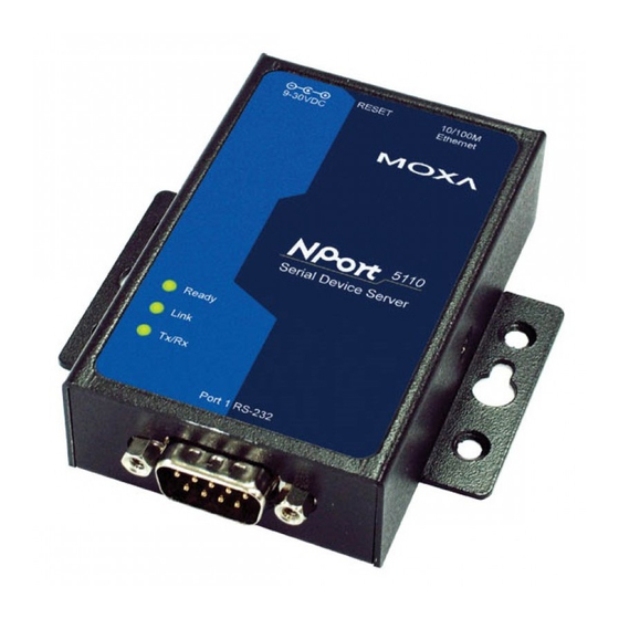
Introduction Chapter 1 NPort 5100 and NPort 5110-T are advanced, 1-port RS-232/422/485 serial device servers that make it easy to network-enable serial devices. The following topics are covered in this chapter: Overview Package Checklist Product Features Product Specifications... -
Page 7: Overview
Introduction Overview NPort 5100 series device servers are designed to make your industrial serial devices Internet ready instantly, and are well-suited for POS security market applications. The compact size of NPort 5100 device servers makes them the ideal choice for connecting your RS-232/422/485 serial... -
Page 8: Product Specifications
NPort 5100 Series User’s Manual Introduction Product Specifications Ethernet 10/100 Mbps, RJ45 Protection Built-in 1.5 KV magnetic isolation NPort 5110 Serial Interface Interface RS-232 No. of Ports Port Type Male DB9 Transmission Speed 230.4 Kbps Signals TxD, RxD, RTS, CTS, DTR, DSR, DCD, GND... - Page 9 NPort 5100 Series User’s Manual Introduction Software Features Protocols ICMP, IP, TCP, UDP, DHCP, BOOTP, Telnet, DNS, SNMP, HTTP, SMTP Utilities NPort Administrator for Windows 95/98/ME/NT/2000/XP/2003 OS Drivers Support Windows 95/98/ME/NT/2000/XP/2003/XP x64/2003 x64/COM driver/Linux Real TTY driver/SCO Unix/SCO OpenServer 5/UnixWare 7/Unix Ware 2.1.x/SVR4.2/QNX...
-
Page 10: Chapter 2 Getting Started
Getting Started Chapter 2 This chapter includes information about installing NPort 5100. The following topics are covered: Panel Layout of NPort 5100 Series Connecting the Hardware Connecting the Power Connecting to the Network Connecting to a Serial Device LED Indicators... -
Page 11: Panel Layout Of Nport 5100 Series
NPort 5100 Series User’s Manual Getting Started Panel Layout of NPort 5100 Series Rear Panel View RJ45 10/100M Ethernet port Reset button Power input Top Panel View RESET 10/100M 12-48 VDC Ethernet DIN-Rail screw hole 5110 Serial Device Server Wallmount... -
Page 12: Connecting To The Network
NPort 5100 Series User’s Manual Getting Started Connecting to the Network Connect one end of the Ethernet cable to NPort 5100’s 10/100M Ethernet port and the other end of the cable to the Ethernet network. NPort 5100 will indicate a valid connection to the Ethernet in... - Page 13 NPort 5100 Series User’s Manual Getting Started ATTENTION Do not use the 1 KΩ setting on the NPort 5150/5130 when using the RS-232 interface. Doing so will degrade the RS-232 signals and shorten the maximum allowed communication distance. NPort 5150/5130 Jumpers...
-
Page 14: Chapter 3 Initial Ip Address Configuration
Initial IP Address Configuration Chapter 3 When setting up your NPort 5100 for the first time, you should first configure the IP address. This chapter introduces the method to configure the device server’s IP address. For more details about network settings, see the Network Settings section from Chapter 5, Web Console Configuration. The following topics are covered in this chapter: Initializing the NPort 5100’s IP Address Factory Default IP Address... -
Page 15: Initializing The Nport 5100'S Ip Address
NPort 5100 Series User’s Manual Initial IP Address Configuration Initializing the NPort 5100’s IP Address 1. Determine whether your NPort 5100 needs to use a Static IP or Dynamic IP (either DHCP or BOOTP application). 2. If the NPort 5100 is used in a Static IP environment, you can use NPort 5100 Administration Suite, ARP, Web Console, Telnet Console, or Serial Console to configure the new IP address. -
Page 16: Telnet Console
NPort 5100 Series User’s Manual Initial IP Address Configuration Take the following steps to use ARP to configure the IP address: 1. Obtain a valid IP address for your NPort 5100 from your network administrator. 2. Obtain the NPort 5100’s MAC address from the label on its bottom panel. - Page 17 NPort 5100 Series User’s Manual Initial IP Address Configuration 4. Type 2 to select Network settings, and then press Enter. 5. Type 1 to select IP address and then press Enter. 6. Use the Backspace key to erase the current IP address, type in the new IP address, and then...
- Page 18 NPort 5100 Series User’s Manual Initial IP Address Configuration 7. Press any key to continue. 8. Type m and then press Enter to return to the main menu. 9. Type s and then press Enter to Save/Restart the system. 10. Type y and then press Enter to save the new IP address and restart the NPort 5100.
-
Page 19: Serial Console (19200, N, 8, 1)
NPort 5100 Series User’s Manual Initial IP Address Configuration Serial Console (19200, n, 8, 1) You may use the RS-232/422/485 console port to set up the IP address for NPort 5100. We suggest using PComm Terminal Emulator, which is available free of charge as part of the PComm Lite program suite (found on the Software CD that comes with the product), to carry out the installation procedure, although other similar utilities may also be used. - Page 20 NPort 5100 Series User’s Manual Initial IP Address Configuration 7. NPort 5100 will receive the “ ` ” string continuously and then auto switch from data mode to console mode. 8. Input the password when prompted. Note that this page will only appear when the NPort 5100 has been set up for password protection.
-
Page 21: Choosing The Proper Operation Mode
Choosing the Proper Operation Mode Chapter 4 In this section, we describe the various NPort 5100 operation modes. The options include Real COM Mode, which uses a driver installed on the host computer, and operation modes that rely on TCP/IP socket programming concepts. After choosing the proper operation mode in this chapter, refer to Chapter 5 for detailed configuration parameter definitions. -
Page 22: Overview
NPort 5100 Series User’s Manual Choosing the Proper Operation Mode Overview NPort 5100 serial device servers network-enable traditional RS-232/422/485 devices, in which a serial device server is a tiny computer equipped with a CPU, real-time OS, and TCP/IP protocols that can bi-directionally translate data between the serial and Ethernet formats. Your computer can access, manage, and configure remote facilities and equipment over the Internet from anywhere in the world. -
Page 23: Tcp Server Mode
NPort 5100 Series User’s Manual Choosing the Proper Operation Mode One of the major conveniences of using Real COM Mode is that Real COM Mode allows users to continue using RS-232/422/485 serial communications software that was written for pure serial communications applications. -
Page 24: Tcp Client Mode
NPort 5100 Series User’s Manual Choosing the Proper Operation Mode TCP Client Mode In TCP Client Mode, the NPort 5100 can actively establish a TCP connection with a pre-determined host computer when serial data arrives. After the data has been transferred, the NPort... -
Page 25: Ethernet Modem Mode
NPort 5100 Series User’s Manual Choosing the Proper Operation Mode Ethernet Modem Mode Ethernet Modem Mode is designed for use with legacy operating systems, such as MS-DOS, that do not support TCP/IP Ethernet. By connecting one of NPort 5100’s serial ports to the MS-DOS computer’s serial port, it is possible to use legacy software originally designed to transmit data via... -
Page 26: Web Console Configuration
Web Console Configuration Chapter 5 The Web Console is the most user-friendly method available to configure NPort 5100. In this chapter, we introduce the Web Console function groups and function definitions. The following topics are covered in this chapter: Opening Your Browser Basic Settings Network Settings Serial Settings... -
Page 27: Opening Your Browser
NPort 5100 Series User’s Manual Web Console Configuration Opening Your Browser 1. Open your browser with the cookie function enabled. (To enable your browser for cookies, right click on your desktop Internet Explorer icon, select Properties, click on the Security tab, and then select the three Enable options as shown in the figure below.) - Page 28 NPort 5100 Series User’s Manual Web Console Configuration 4. The NPort 5100 homepage will open next. On this page, you can see a brief description of the Web Console’s nine function groups. ATTENTION If you can’t remember the password, the ONLY way to start configuring the NPort 5100 is to load factory defaults by using the Reset button located near the NPort 5100’s RJ45 Ethernet port.
-
Page 29: Basic Settings
NPort 5100 Series User’s Manual Web Console Configuration Basic Settings Server name Setting Factory Default Necessity 1 to 39 characters NP[model name]_[Serial No.] Optional This option is useful for specifying the location or application of different NPort 5100s. Web/Telnet Console The “Disable”... -
Page 30: Network Settings
NPort 5100 Series User’s Manual Web Console Configuration Network Settings You must assign a valid IP address to the NPort 5100 before it will work in your network environment. Your network system administrator should provide you with an IP address and related settings for your network. - Page 31 NPort 5100 Series User’s Manual Web Console Configuration Netmask Setting Factory Default Necessity E.g., 255.255.255.0 255.255.255.0 Required A subnet mask represents all of the network hosts at one geographic location, in one building, or on the same local area network. When a packet is sent out over the network, the NPort 5100 will use the subnet mask to check whether the desired TCP/IP host specified in the packet is on the local network segment.
-
Page 32: Snmp Settings
NPort 5100 Series User’s Manual Web Console Configuration SNMP Settings Community name Setting Factory Default Necessity 1 to 39 characters public Optional A community name is a plain-text password mechanism that is used to weakly authenticate queries to agents of managed network devices. -
Page 33: Serial Settings
NPort 5100 Series User’s Manual Web Console Configuration Serial Settings Click Serial Settings, located under Main Menu, to display serial port settings for port 1. To modify serial settings for a particular port, click either Port 1 under Serial Settings, located under Main Menu on the left side of the browser window. -
Page 34: Operating Settings
NPort 5100 Series User’s Manual Web Console Configuration Stop bits Setting Factory Default Necessity 1, 1.5, 2 Required Stop bits will be set to 1.5 when Data bits is set to 5 bits. Parity Setting Factory Default Necessity None, Even, Odd, Space, Mark... -
Page 35: Real Com Mode
NPort 5100 Series User’s Manual Web Console Configuration Real COM Mode TCP alive check time Setting Factory Default Necessity 0 to 99 min 7 min Optional 0 min: TCP connection is not closed due to an idle TCP connection. 1 to 99 min: NPort 5100 automatically closes the TCP connection if there is no TCP activity for the given time. - Page 36 NPort 5100 Series User’s Manual Web Console Configuration ATTENTION When Max connection is set to 2, 3, or 4, this means that the NPort 5100 will be using a “multi connection application” (i.e., 2, 3, or 4 hosts are allowed access to the port at the same time).
- Page 37 NPort 5100 Series User’s Manual Web Console Configuration ATTENTION Delimiter 2 is optional. If left blank, then Delimiter 1 alone trips clearing of the buffer. If the size of the serial data received is greater than 1 KB, the NPort 5100 will automatically pack the data and send it to the Ethernet.
-
Page 38: Tcp Server Mode
NPort 5100 Series User’s Manual Web Console Configuration TCP Server Mode TCP alive check time Setting Factory Default Necessity 0 to 99 min 7 min Optional 0 min: TCP connection is not closed due to an idle TCP connection. 1 to 99 min: The NPort 5100 automatically closes the TCP connection if there is no TCP activity for the given time. - Page 39 NPort 5100 Series User’s Manual Web Console Configuration ATTENTION The Inactivity time should at least be set larger than that of Force transmit timeout. To prevent the unintended loss of data due to the session being disconnected, it is highly recommended that this value is set large enough so that the intended data transfer is completed.
- Page 40 NPort 5100 Series User’s Manual Web Console Configuration Delimiter 2 Setting Factory Default Necessity 00 to FF None Optional Once the NPort 5100 receives both delimiters through its serial port, it immediately packs all data currently in its buffer and sends it out the NPort 5100’s Ethernet port.
-
Page 41: Tcp Client Mode
NPort 5100 Series User’s Manual Web Console Configuration If the user wants to send a series of characters in the same packet, the serial device attached to NPort 5100 should send that series of characters during a time interval less than the Force transmit timeout for NPort 5100, and the total length of data must be less than or equal to NPort 5100’s... - Page 42 NPort 5100 Series User’s Manual Web Console Configuration TCP alive check time Setting Factory Default Necessity 0 to 99 min 7 min Optional 0 min: TCP connection is not closed due to an idle TCP connection. 1 to 99 min: NPort 5100 automatically closes the TCP connection if there is no TCP activity for the given time.
- Page 43 NPort 5100 Series User’s Manual Web Console Configuration Delimiter 1 Setting Factory Default Necessity 00 to FF (hex) None Optional Delimiter 2 Setting Factory Default Necessity 00 to FF (hex) None Optional Once the NPort 5100 receives both delimiters through its serial port, it immediately packs all data currently in its buffer and sends it to the NPort 5100’s Ethernet port.
- Page 44 NPort 5100 Series User’s Manual Web Console Configuration If the user wants to send a series of characters in the same packet, the serial device attached to NPort 5100 should send that series of characters during a time interval less than the Force transmit timeout for NPort 5100, and the total length of data must be less than or equal to NPort 5100’s...
-
Page 45: Udp Mode
NPort 5100 Series User’s Manual Web Console Configuration Connect/Disconnect Description Startup/None A TCP connection will be established on startup, and will remain active (default) indefinitely. A TCP connection will be established when any character is received Any Character/None from the serial interface, and will remain active indefinitely. - Page 46 NPort 5100 Series User’s Manual Web Console Configuration Delimiter 1 Setting Factory Default Necessity 00 to FF None Optional Delimiter 2 Setting Factory Default Necessity 00 to FF None Optional Once the NPort 5100 receives both delimiters through its serial port, it immediately packs all data currently in its buffer and sends it out the NPort 5100’s Ethernet port.
-
Page 47: Pair Connection Mode
NPort 5100 Series User’s Manual Web Console Configuration If the user wants to send a series of characters in the same packet, the serial device attached to NPort 5100 should send that series of characters during a time interval less than the Force transmit timeout for NPort 5100, and the total length of data must be less than or equal to NPort 5100’s... -
Page 48: Pair Connection Slave Mode
NPort 5100 Series User’s Manual Web Console Configuration TCP alive check time Setting Factory Default Necessity 0 to 99 min Required 7 min 0 min: TCP connection is not closed due to an idle TCP connection. 1 to 99 min: The NPort 5100 closes the TCP connection automatically if there is no TCP activity for the given time. -
Page 49: Ethernet Modem Mode
NPort 5100 Series User’s Manual Web Console Configuration Ethernet Modem Mode Dial-in NPort 5100 listens for a TCP/IP connection request from the remote Ethernet modem or host. NPort 5100’s response depends on the ATS0 value, as outlined below. ATS0=0 (default): NPort 5100 will temporarily accept the TCP connection and then send the “RING”... - Page 50 NPort 5100 Series User’s Manual Web Console Configuration AT Commands NPort 5100 supports the following common AT commands used with a typical modem: No. AT command Description Remarks Answer manually ATD <IP>:<Port> Dial up the IP address: Port No. ATE0=Echo OFF...
-
Page 51: Reverse Telnet Mode
NPort 5100 Series User’s Manual Web Console Configuration S Registers No. S Register Description & default value Remarks Ring to auto-answer (default=0) Ring counter (always=0) no action applied Escape code character (default=43 ASCII “+”) Return character (default=13 ASCII) Line feed character (default=10 ASCII) -
Page 52: Disabled Mode
NPort 5100 Series User’s Manual Web Console Configuration TCP alive check time Setting Factory Default Necessity 0 to 99 min 7 min Optional 0 min: TCP connection is not closed due to an idle TCP connection. 1 to 99 min: NPort 5100 automatically closes the TCP connection if there is no TCP activity for the given time. -
Page 53: Accessible Ip Settings
NPort 5100 Series User’s Manual Web Console Configuration Accessible IP Settings The NPort 5100 uses an IP address based filtering method to control access to itself. Accessible IP Settings allows you to add or block remote host IP addresses to prevent unauthorized access. -
Page 54: Auto Warning Settings
NPort 5100 Series User’s Manual Web Console Configuration Auto Warning Settings Auto warning: Email and SNMP trap Mail Server Mail server Setting Factory Default Necessity IP Address or Domain Name None Optional User name Setting Factory Default Necessity 1 to 15 characters... -
Page 55: Event Type
NPort 5100 Series User’s Manual Web Console Configuration ATTENTION Consult your Network Administrator or ISP for the proper mail server settings. The Auto warning function may not work properly if it is not configured correctly. NPort 5100 SMTP AUTH supports LOGIN, PLAIN, CRAM-MD5 (RFC 2554). -
Page 56: Monitor
NPort 5100 Series User’s Manual Web Console Configuration DCD changed The DCD (Data Carrier Detect) signal has changed, also indicating that the modem connection status has changed. For example, a DCD change to high also means “Connected” between local modem and remote modem. If the DCD signal changes to low, it also means that the connection line is down. -
Page 57: Monitor Async
NPort 5100 Series User’s Manual Web Console Configuration Monitor Async Click Async under Monitor to show the current status of the serial port. Monitor Async-Settings Click Async Setting under Monitor to show the run-time settings for the serial port. Change Password Input the “Old password”... -
Page 58: Load Factory Default
NPort 5100 Series User’s Manual Web Console Configuration Load Factory Default This function will reset all of NPort 5100’s settings to the factory default values. Be aware that previous settings will be lost. 5-33... -
Page 59: Configuring Nport Administrator
Configuring NPort Administrator Chapter 6 The following topics are covered in this chapter: Overview Installing NPort Administrator Configuration Broadcast Search Unlock Password Protection Configuring the NPort 5100 Upgrading the Firmware Export Configuration Import Configuration Monitor Port Monitor COM Mapping On-line COM Mapping Off-line COM Mapping IP Address Report... -
Page 60: Overview
Configuring NPort Administrator Overview Device Server Administrator lets you install and configure your NPort 5100 Series products easily over the network. Five function groups are provided to ease the installation process, allow off-line COM mapping, and provide monitoring and IP location server functions. - Page 61 NPort 5100 Series User’s Manual Configuring NPort Administrator 3. Click Next to install the program using the default program name, or select a different name. 4. Click Install to proceed with the installation. 5. The Installing window reports the progress of the installation.
-
Page 62: Configuration
NPort 5100 Series User’s Manual Configuring NPort Administrator 6. Click Next to proceed with the installation. 7. Click Finish to complete the installation of NPort 5100 Administration Suite. Configuration The Administrator-Configuration window is divided into four parts. • The top section contains the function list and online help area. (Windows NT does not support this .chm file format.) -
Page 63: Broadcast Search
NPort 5100 Series User’s Manual Configuring NPort Administrator Broadcast Search The Broadcast Search function is used to locate all NPort 5100s that are connected to the same LAN as your computer. Since the Broadcast Search function searches by MAC address and not IP address, all NPort 5100s connected to the LAN will be located, regardless of whether or not they are part of the same subnet as the host. -
Page 64: Unlock Password Protection
NPort 5100 Series User’s Manual Configuring NPort Administrator 2. The Broadcast Search window will open and display the Model, IP Address, MAC Address, and Progress of the search for that particular device. 3. When the search is complete, the Broadcast Search window will close, and the NPort 5100s that were located will be displayed in the right pane of the Administrator window. - Page 65 NPort 5100 Series User’s Manual Configuring NPort Administrator 1. Select the NPort 5100 with “Lock” status, click the right mouse button, and then select Unlock. 2. After inputting the correct password, the Administrator will display an “Unlock ok” message. 3. The “Lock” status will change to “Unlock,” and the Administrator utility will keep this NPort 5100 in the Unlock status throughout this Administrator session.
-
Page 66: Configuring The Nport 5100
NPort 5100 Series User’s Manual Configuring NPort Administrator Unlock The NPort 5100 is password protected, “Broadcast Search” was used to locate it, and the password has been entered from within the current Administrator session. Henceforth during this Administrator session, activating various utilities for this NPort 5100 will not require re-entering the server password. -
Page 67: Upgrading The Firmware
NPort 5100 Series User’s Manual Configuring NPort Administrator 3. The progress bar shows that Administrator is retrieving configuration information from the specific NPort 5100. 4. Refer to Chapter 5 for each parameter’s function definition. To modify the configuration, you must first click in the modify box to activate the parameter setting box. - Page 68 NPort 5100 Series User’s Manual Configuring NPort Administrator 2. Unlock the NPort 5100 you wish to configure if it is password protected. Right click a specific NPort 5100 and select the Upgrade Firmware function to start upgrading the firmware. 3. Select the correct ROM file to download.
-
Page 69: Export Configuration
NPort 5100 Series User’s Manual Configuring NPort Administrator Export Configuration To export the configuration of an NPort 5100, right click the NPort 5100, select Export Configuration, and then follow the onscreen instructions. The Export Configuration function is a handy tool that can be used to produce a text file containing the current configuration of a particular NPort 5100. -
Page 70: Monitor
NPort 5100 Series User’s Manual Configuring NPort Administrator ATTENTION You can simultaneously import the same configuration file into multiple NPort 5100s that are of the same model. To select multiple NPort 5100s, hold down the Ctrl key when selecting an additional NPort 5100, or hold down the Shift key to select a block of NPort 5100s. - Page 71 NPort 5100 Series User’s Manual Configuring NPort Administrator Monitor Add Target Rescan 1. Click Monitor under Function. 2. Click Monitor Add Target from the menu bar, or click the right mouse button and select Add Target. 3. Click Rescan. 6-13...
- Page 72 NPort 5100 Series User’s Manual Configuring NPort Administrator 4. Select your targets from the list, and then click OK. Once the Monitor function is running: 1. The NPort 5100 list will appear on the Monitor screen. 2. Right click the panel and select Settings.
- Page 73 NPort 5100 Series User’s Manual Configuring NPort Administrator 3. Select or de-select Monitor Items. Use the single arrowhead buttons to move highlighted items from one box to the other. Use the double arrowhead buttons to move all items in one box to the other.
- Page 74 NPort 5100 Series User’s Manual Configuring NPort Administrator 5. On the Advanced Settings page, select Display warning message for new event and/or Play warning music for new event. In the second case, you must enter the path to the WAV file that you want to be played.
- Page 75 NPort 5100 Series User’s Manual Configuring NPort Administrator 8. When one of the NPort 5100s loses connection with the Monitor program, a warning alert will display automatically. The warning music will be played at the same time. 9. In the Monitor screen, you can see that the NPort 5100s that are “Not Alive” are shown in red color.
-
Page 76: Port Monitor
NPort 5100 Series User’s Manual Configuring NPort Administrator Port Monitor The process described here is the same as in the previous “Monitor” section. The only difference is that you can select more items under Port Monitor than under Monitor. Select or de-select Monitor Items. Use the single arrowhead buttons to move highlighted items from one box to the other. -
Page 77: On-Line Com Mapping
NPort 5100 Series User’s Manual Configuring NPort Administrator 2. Off-line COM Mapping: Map COMs to your host Apply Change Connect the NPort 5100 to the network Configure NPort 5100’s IP address. On-line COM Mapping 1. Broadcast Search for NPort 5100s on the network. - Page 78 NPort 5100 Series User’s Manual Configuring NPort Administrator 5. Select COM Settings to modify COM No., default setting, etc. 6. Select the COM Number. COM ports that are “In use” or “Assigned” will also be indicated in this drop-down list. If you select multiple serial ports or multiple NPort 5100s, remember to check the “Auto...
- Page 79 NPort 5100 Series User’s Manual Configuring NPort Administrator function, the NPort driver will keep querying the NPort’s firmware several times to make sure there is really no data queued in the NPort firmware buffer, rather than just flushing the local buffer. This kind of design is used because of some special considerations.
- Page 80 NPort 5100 Series User’s Manual Configuring NPort Administrator 9. After setting the COM Mapping, remember to select Apply Change to save the information in the host system registry. The host computer will not have the ability to use the COM port until after Apply Change is selected.
-
Page 81: Off-Line Com Mapping
NPort 5100 Series User’s Manual Configuring NPort Administrator Off-line COM Mapping 1. Add a target by inputting the IP address and selecting the Model Name without physically connecting the NPort 5100 to the network. 2. Modify the port settings as needed. -
Page 82: Ip Address Report
When NPort 5100 is used in a dynamic IP environment, users must spend more time with IP management tasks. NPort 5100 Series products help out by periodically reporting their IP address to the IP location server, in case the dynamic IP has changed. - Page 83 NPort 5100 Series User’s Manual Configuring NPort Administrator 4. Click Go to start receiving the Auto IP address report from the NPort 5100. 6-25...
-
Page 84: Ip Serial Lib
IP Serial LIB Chapter 7 The following topics are covered in this chapter: Overview IP Serial LIB Function Groups Example Program... -
Page 85: Overview
NPort 5100 Series User’s Manual IP Serial LIB Overview What is IP Serial Library? IP Serial Library is a Windows library with frequently used serial command sets and subroutines. IP Serial Library is designed to reduce the complexity and poor efficiency of serial communication over TCP/IP. -
Page 86: Ip Serial Lib Function Groups
NPort 5100 Series User’s Manual IP Serial LIB IP Serial LIB Function Groups Server Control Port Control Input/Output Data Port Status Miscellaneous Inquiry nsio_init nsio_open nsio_read nsio_lstatus nsio_break nsio_end nsio_close nsio_SetReadTimeouts nsio_data_status nsio_break_on nsio_resetserver nsio_ioctl nsio_write nsio_break_off nsio_checkalive nsio_flowctrl nsio_SetWriteTimeouts... -
Page 87: Appendix A Pinouts And Cable Wiring
Pinouts and Cable Wiring Appendix A The following topics are covered in this appendix: Port Pinout Diagrams Ethernet Port Pinouts NPort 5110 Serial Port Pinouts NPort 5130 Serial Port Pinouts NPort 5150 Serial Port Pinouts Cable Wiring Diagrams Ethernet Cables... -
Page 88: Port Pinout Diagrams
NPort 5100 Series User’s Manual Pinouts and Cable Wiring Port Pinout Diagrams Ethernet Port Pinouts Signal NPort 5110 Serial Port Pinouts DB9 Male RS-232 Port Pinouts for NPort 5110/5110-T RS-232 NPort 5130 Serial Port Pinouts DB9 Male RS-422/485 Port Pinouts for NPort 5130/5130-T... -
Page 89: Cable Wiring Diagrams
NPort 5100 Series User’s Manual Pinouts and Cable Wiring Cable Wiring Diagrams Ethernet Cables Straight-Through Cable RJ45 Plug Pin 1 Cable Wiring Cross-Over Cable RJ45 Plug Pin 1 Cable Wiring... -
Page 90: Appendix B Well Known Port Numbers
Well Known Port Numbers Appendix B In this appendix, which is included for your reference, we provide a list of Well Known port numbers that may cause network problems if you set NPort 5100 to one of these ports. Refer to RFC 1700 for Well Known port numbers, or refer to the following introduction from the IANA. - Page 91 NPort 5100 Series User’s Manual Well Known Port Numbers TCP Socket Application Service Network News Transfer Protocol (NNTP) Network Time Protocol 160 – 223 Reserved for future use UDP Socket Application Service Reserved Management Utility Echo Discard Active Users (systat)
- Page 92 SNMP Agents with MIB II & Appendix C RS-232/422/485 Link Groups NPort 5100 has built-in SNMP (Simple Network Management Protocol) agent software that supports SNMP Trap, RFC1317 RS-232/422/485 like groups and RFC 1213 MIB-II. The following table lists the standard MIB-II groups, as well as the variable implementation for NPort 5100.
- Page 93 NPort 5100 Series User’s Manual SNMP Agents with MIB II & RS-232/422/485 Link groups System MIB Interfaces MIB IP MIB ICMP MIB ipAdEntReasmMaxSize IcmpOutAddrMasks IpNetToMediaIfIndex IcmpOutAddrMaskReps IpNetToMediaPhysAddress IpNetToMediaNetAddress IpNetToMediaType IpRoutingDiscards UDP MIB TCP MIB SNMP MIB UdpInDatagrams tcpRtoAlgorithm snmpInPkts UdpNoPorts...
- Page 94 NPort 5100 Series User’s Manual SNMP Agents with MIB II & RS-232/422/485 Link groups RFC1317: RS-232/422/485 MIB objects Generic RS-232/422/485-like RS-232/422/485-like General RS-232/422/485-like Group Port Table Asynchronous Port Group rs232Number rs232PortTable rs232AsyncPortTable rs232PortEntry rs232AsyncPortEntry rs232PortIndex rs232AsyncPortIndex rs232PortType rs232AsyncPortBits rs232PortInSigNumber rs232AsyncPortStopBits...
-
Page 95: Appendix D Auto Ip Report Protocol
Auto IP Report Protocol Appendix D NPort Series provides several ways to configure Ethernet IP addresses. One of them is DHCP Client. When you set up the NPort to use DHCP Client to configure Ethernet IP addresses, it will automatically send a DHCP request over the Ethernet to find the DHCP Server. And then the DHCP Server will send an available IP address to the NPort. - Page 96 NPort 5100 Series User’s Manual Auto IP Report Protocol Auto IP Report Format “MOXA”, 4 bytes Info[0] Info[1] … Info[n] Info [n] Field Length Data Length Variable, Length is “Length Field” ID List ID Value Description Length Note Server Name...
- Page 97 Soporte en Ingeniería y Equipos, S.A de C.V ¡SOLUCIONES! Para el ahorro y control de la energía eléctrica AGUASCALIENTES (MATRIZ) Priv. Cerro de la bufa No. 105 Fracc. Lomas del Campestre Aguascalientes, Ags. C.P. 20129 Tel: (449) 145 6701 Fax:(449) 145 6703 GUADALAJARA Siempre Viva No.
Need help?
Do you have a question about the NPort 5100 Series and is the answer not in the manual?
Questions and answers