
Related Manuals for Siemens Gigaset M 101 Data


Summary of Contents for Siemens Gigaset M 101 Data
- Page 1 The cordless V.24/RS232 interface for PCs, modems and other equipment Operating instruction Please read the safety precautions outlined in these operating instructions before putting the unit into service.
- Page 2 The most important menus Starting the program Registering a Gigaset M101 Data Setting the operating mode...
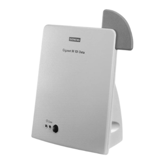
- Page 3 Overview Legend Front Operating LED, illuminated when power supply is active, see "LEDs and buttons" on page 2. Data LED, illuminated during data transfer operations 3. Reset key 1 2 3 Back 4. Port for the V.24/RS232 cable 1 = male 2 = female 5.
-
Page 4: Table Of Contents
Contents Updates and news on the Internet ....................5 Approval and conformity ........................ 6 Notes on PC and modem operation ....................6 Notes on Gigaset Repeater ......................6 Introduction ..........................7 What is a Gigaset M101 Data? ...................... 7 Safety precautions ........................7 Putting into service ........................ -
Page 5: Updates And News On The Internet
Notes on sending faxes directly from the PC ................34 Configuration management ....................35 Problems with application programs: ..................35 Hardware problems (PC, modem, ISDN TA.): ............... 36 Miscellaneous ........................37 Updates and news on the Internet Visit our site at: www.siemens.com/pc-communication-support (always under construction) -
Page 6: Approval And Conformity
Approval and conformity Your Siemens Gigaset M101 Data has been certified by the Ger- man Federal Office of Telecommunication Approval (BZT). This equipment has been approved in accordance with the EU direc- tive 91/263/EC Telecommunication Terminals. This data terminal complies with the requirements of the EU di-... -
Page 7: Introduction
Introduction Introduction What is a Gigaset M101 Data? Your Gigaset M101 Data is a cordless V.24/RS232 serial inter- face consisting of two stations: the lokalen Station and the Part- nerstation. The station connected to the PC is known as the "lokale Station". The "Partnerstation"... -
Page 8: Putting Into Service
Putting into service Putting into service Follow the step-by-step instructions described below for putting the equipment into service: Check the contents of the package 2. Install the configuration program 3. Connect the station 4. Conclude commissioning by performing an initial configura- tion, see "Initial configuration"... -
Page 9: Installing The Program Package
Putting into service Installing the program package Prerequisites for installation For installation, you need: an IBM-compatible PC with the following configuration: – Win 95, Win 98 or Win NT operating system – 2 MB free hard disk memory – 1 free V.24/RS232 serial interface as COM port the diskette/CD-ROM containing the installation program Installation... -
Page 10: Connecting Stations
Putting into service Connecting stations To avoid damaging your Gigaset M101 Data and the PC, the V.24/RS232 cable should only be connected when the pow- er supply is switched off. Connect a Gigaset M101 Data to the V.24/RS232 interface of the PC (COM port). Some V.24 plugs have a plastic pro- trusion and cannot be properly arrested. -
Page 11: Initial Configuration
Initial configuration Initial configuration The purpose of initial configuration is to register the Teilnehmer station at the Basis station. You can only perform initial configu- ration with the configuration program. The Gigaset M101 Data can be operated at other PCs/operating systems once you have completed initial configuration. -
Page 12: Configuration Program Options
Configuration program options Configuration program options General You will rarely need the majority of configuration options for the simple implementation of two Gigaset M101 Data units for cord- less modem operation. A range of settings is available for future developments. Starting the configuration program Under Start, select Programs followed by Gigaset M101 Data and finally Set Gigaset. -
Page 13: Connection" Tab
Configuration program options "Connection" tab Upper section: connecting to the PC You can set the COM port of the PC at which the lokale Station is connected in the upper section of the tab. It is easiest to leave the option No automatic detection deacti- vated (as shown). -
Page 14: Operating Mode" Tab
Configuration program options "Operating mode" tab Important: If one station is set to "AT commands, local" or "AVM/Eumex commands, local", the other station must switch to the corre- sponding "AT commands, remote" or "AVM/Eumex commands, remote" operating mode. And if one station is switched to "Di- rect connection", the other station must also be switched to this mode. -
Page 15: Special Settings For "Direct Connection" Mode
Configuration program options AVM / Eumex Automatic emulation of the AVM / Eumex Partnerstation transmission parameters based on the val- (device) ues received from the PC at the Partner- station. Special settings for "Direct connection" mode In the Direct connection setting, the fields are activated in the lower section of the dialog box: you can set the transmission pa- rameters for the COM port at the PC: Select the masked-in setting if you have no reason to reject it. - Page 16 Configuration program options Changing a station type Normally, a Teilnehmer station is operated at the PC and the Ba- sis station is operated at a peripheral device. Other constella- tions, however, are possible in which both stations are connect- ed to another PC, in order to create a cordless data connection between two PCs.
-
Page 17: Registering An Extension Station
Configuration program options Registering an Teilnehmer station Both stations are powered. A Gigaset M101 Data is connected to the PC. Select the Local station tab. The following dialog box appears: An existing registered device in the "Registered stations" win- dow must first be deleted. This is done in the "Partner station" tab, see "Resetting the device to the factory default"... -
Page 18: De-Registering A Extension Station
Configuration program options The Teilnehmer station now searches for the Basis station and automatically registers at it. If registration is not possible (Basis station not in "logon mode" or not powered, incorrect PIN), the system will indicate the nec- essary steps for resolving this problem. De-registering a Teilnehmer station De-registration is only possible by resetting the Gigaset M101 Data unit to the factory default, see "Resetting the device to the... -
Page 19: Leds And Buttons
LEDs and buttons LEDs and buttons There are two LEDs and a black button on the front of the Gigas- et M101 Data unit. Both button functions Setting a Basis to logon mode Press the button on a powered base-type device for 10 seconds. The two LEDs blink in sequence, thus indicating that the device is in logon mode. -
Page 20: What Happens If
Gigaset M101 Data units to the factory defaults, see page 19. If the malfunction persists, call the hotline at 0180 5 333 220. Internet: www.siemens.de/gigaset Notes on installation and operation Place of installation There must be a 220/230 V AC 50 Hz power socket in the vicin- ity. -
Page 21: Temperature And Ambient Conditions
What happens if... Temperature and ambient conditions The Gigaset M101 Data is designed for operation in protected rooms with a temperature range from +5°C to +45°C. Do not set up the Gigaset M101 Data in damp environments, such as a bathroom or laundry room. Do not expose it to direct sunlight or other heat sources, such as radiators. -
Page 22: The V.24 Interface
The V.24 interface Name Based on CCITT Meaning Std. Pin Assign. 25-pin 9-pin 109 = Data Carrier Detect Data carrier signal 106 = Clear To Send Clear to send signal 107 = Data Send Ready Data send ready 108 = Data Terminal Ready Data terminal ready 102 = Signal Ground Signal ground... -
Page 23: Why Set A Mode? Technical Background
Why set a mode? Technical background Serial interfaces are more than plug-in connections. They have an integrated data flow control, control lines, data lines and an adjustable speed function. Serial interfaces are used for trans- porting data in various formats. Modems are usually controlled with AT commands or company- specific protocols commands that they receive via their serial in- terface. -
Page 24: Tips & Tricks, Settings
Tips & tricks, settings Tips & tricks, settings This section describes settings, implementation options and programming methods. Operating from a local station with two remote stations: Please note that Only one connection can be active. Only one "Teilnehmer" station type can be registered at a base that is ready for registration. -
Page 25: Pc - Pc Direct Cable Connection: Via Rs232/V.24 Interface
Tips & tricks, settings To switch from Gigaset 2 to 3, simply click Change station type on the Local Station tab. Teilnehmer Basis Teilnehmer Basis V.24 V.24-DECT PC with configuration program Gigaset 1 Gigaset 64 kbit/s Switch M101 the connection Base Extension by changing the... -
Page 26: Setting The Direct Connection To The Correct Baud Rate
Tips & tricks, settings Setting the direct connection to the correct baud rate Open the terminal program The first step is to open a terminal program on both PCs (e.g. Win95 HyperTerminal via Hypertrm.exe) and to ensure that the correct COM port is being accessed, Set up a direct connection via COMx (COM 1 is selected in the example). - Page 27 Tips & tricks, settings The baud rate (max. 115,200) and HW handshake (default setting) are set in this mask. If you are able to transmit data from one PC to the other, proceed now to the second step. 2. Set direct cable connection parameters Exit the terminal program at one of the PCs.
- Page 28 Tips & tricks, settings You will find maximum speed setting in the Modem tab; this should be set to 115,200 bps. Activate Hardware under Use flow control in the Settings - Advanced tab. Click OK to exit each window. 3. Test the baud rate setting Open the direct cable connection program via Start Programs...
- Page 29 Tips & tricks, settings Select Modify under Settings and activate Guest. Enter the port, e.g. “Null-Modem Cable at COM 1” . To enable access by the other PC, the host (controlling) and guest (accessing), as well as the file and print sharing option must be activated.
- Page 30 Tips & tricks, settings Click File and Print Sharing in the sub-window. Set the parameters here. If a modification was made, new drivers are loaded and Windows must be restarted. If file and print sharing was already activated, the computer does not need to be restarted.
- Page 31 Tips & tricks, settings If the computer was not restarted, the following window ap- pears: If file/printer sharing has not yet been activated, you can activate this feature, see "Sharing files" on page 32. In the final window, select Finish and click OK to answer the questions.
-
Page 32: Sharing Files
Tips & tricks, settings Sharing files Since the Windows information given in the previous mask is somewhat confusing, and since no references are made to the File Manager/Explorer, here is the correct procedure. Once file sharing has been activated and the PC restarted, you can re- lease files for processing by the other PC via the File Manager/ Explorer. -
Page 33: Pc - Pc Direct Cable Connection Problems: Examples
Tips & tricks, settings PC - PC direct cable connection problems: examples Other modem drivers installed continue to operate at the same COM port (special ISDN TA drivers, CAPI modem drivers or sim- ilar software are often the cause of the problem). Once successfully put into service, you can start up the direct cable connection at both PCs. -
Page 34: Support
Hayes commands. Support Updates and news on the Internet www.siemens.com/pc-communication-support Notes on sending faxes directly from the PC You may encounter problems if your PC program uses Class 1 fax mode. Class 1 does not support any delays in signal runt- imes which are necessary for switching to radio mode. -
Page 35: Configuration Management
Tips & tricks, settings Configuration management Fault Cause Solution Configuration program displays The COM port used is being Close the application that is us- the message "A Gigaset M101 used by another program. ing the COM port. Data could not be found". Configuration on an Apple Mac- The Mac interface is an RS422 Configure Gigaset M101 Data... -
Page 36: Hardware Problems (Pc, Modem, Isdn Ta.)
Tips & tricks, settings Fault Cause Solution The modem parameter request Windows is not respecting the None function is not working or is not AT Hayes conditions. correct. Technically specified time de- None For example, under Win 95 with lays that are not supported by <Start><Settings><Control the modem’s driver software. -
Page 37: Miscellaneous
M101 Data further away and thus produces a humming from the sound card/loudspeak- sound. ers. Issued by © Siemens AG 1999. All rights reserved. Information and Communication Products Subject to availability. Hofmannstraße 51, D-81359 München Right of modification reserved. Siemens Aktiengesellschaft Ref.
Need help?
Do you have a question about the Gigaset M 101 Data and is the answer not in the manual?
Questions and answers