Table of Contents
Advertisement
AUTO WASHER
AUTO WASHER
WASHER
AUTO WASHER
AUTO WASHER
AUTO WASHER
AUTO WASHER
WASHER
AUTO WASHER
AUTO WASHER
AUTO WASHER
AUTO WASHER
WASHER
AUTO WASHER
AUTO WASHER
AUTO WASHER
AUTO WASHER
WASHER
AUTO WASHER
AUTO WASHER
AUTO WASHER
AUTO WASHER
AUTO WASHER
AUTO WASHER
AUTO WASHER
AUTO WASHER
AUTO WASHER
AUTO WASHER
AUTO WASHER
AUTO WASHER
AUTO WASHER
AUTO WASHER
C C o o n n t t e e n n t t s s
1. SPECIFICATIONS....................................................................................................................2
2. INSTALLATION ........................................................................................................................3
Removing transit bolts ......................................................................................................3
Installation place requirement...........................................................................................4
BS Plug Safety Details (For U.K. User)............................................................................4
Connecting inlet hose .......................................................................................................5
Installation of drain hose...................................................................................................6
Level adjustment...............................................................................................................7
3. MAINTENANCE .......................................................................................................................8
Cleaning your washer .......................................................................................................8
Cold condition ...................................................................................................................8
Cleaning the water inlet filter ............................................................................................9
Cleaning the drain pump filter...........................................................................................9
Cleaning the detergent case...........................................................................................10
Cleaning the washing drum ............................................................................................10
4. DIRECTION FOR DISASSEMBLY ........................................................................................11
5. EXPLODE VIEW AND PARTS LIST .....................................................................................14
6. FUNCTIONS OF THE CONTROL PANEL ............................................................................22
7. FUNCTIONS OF THE CONTROLLER..................................................................................24
8. FUNCTION OF THE CONVENIENT SERVICE.....................................................................26
9. TROUBLESHOOTING GUIDE ..............................................................................................27
10. WIRING DIAGRAM ..............................................................................................................30
AUTO WASHER
AUTO WASHER
AUTO WASHER
AUTO WASHER
AUTO WASHER
AUTO WASHER
AUTO WASHER
AUTO WASHER
AUTO WASHER
AUTO WASHER
AUTO WASHER
AUTO WASHER
AUTO WASHER
AUTO WASHER
AUTO WASHER
AUTO WASHER
AUTO WASHER
AUTO WASHER
AUTO WASHER
AUTO WASHER
AUTO WASHER
AUTO WASHER
AUTO WASHER
AUTO WASHER
AUTO WASHER
AUTO WASHER
AUTO WASHER
AUTO WASHER
AUTO WASHER
AUTO WASHER
AUTO WASHER
AUTO WASHER
AUTO
AUTO WASHER
AUTO
AUTO WASHER
AUTO
AUTO WASHER
AUTO
AUTO WASHER
Advertisement
Table of Contents

Subscribe to Our Youtube Channel
Related Manuals for Daewoo DWD-F101(1~3)


Summary of Contents for Daewoo DWD-F101(1~3)
-
Page 1: Table Of Contents
AUTO WASHER AUTO WASHER AUTO WASHER AUTO WASHER AUTO WASHER AUTO WASHER AUTO WASHER AUTO WASHER AUTO WASHER AUTO WASHER AUTO WASHER AUTO WASHER AUTO WASHER AUTO WASHER AUTO WASHER AUTO WASHER AUTO WASHER AUTO WASHER AUTO WASHER AUTO WASHER AUTO WASHER AUTO WASHER AUTO WASHER... -
Page 2: Specifications
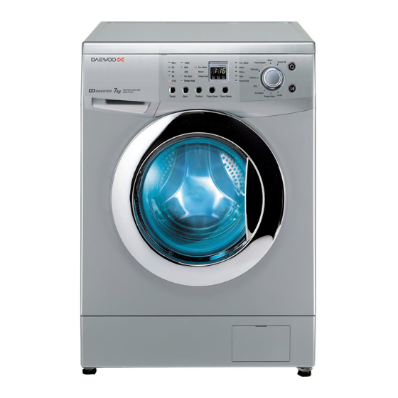
1. SPECIFICATIONS INLET HOSE DETERGENT CASE POWER CORD CONTROL PANEL DOOR HOSE DRAIN ADJUSTABLE LEG LOWER COVER DWD-F101(1~3) / F121(1~3) POWER SOURCE 220-240V, 50Hz DiMENSION (WXDXH) 595mm x 540mm x 850mm WEIGHT 64kg WATER CONSUMPTION POWER CONSUMPTION 2000W MAXIMUM MASS WASH OF TEXTILE SPIN... -
Page 3: Installation
2. INSTALLATION Transit bolts Transit bolts The appliance is fitted with transit bolts to prevent internal damage during transport. The appliance is fitted with transit bolts to prevent internal damage during transport. Removing transit bolts Removing transit bolts 1. To prevent internal damage during trnasport, the 2. -
Page 4: Installation Place Requirement
Installation place requirement Level floor : Allowable slope under entire washer is 1° Power outlet : Must be with 1,5 meters of entire side of location of washer. Do not overload the outlet with more than one appliance. Additional Clearance : For wall, door and floor modeling is required. -
Page 5: Connecting Inlet Hose
Connecting inlet hose In using only one water tap or in case of only one water inlet valve, connect the inlet hose to the cold water inlet valve. Option : Be careful not to confuse hot water inlet and cold water inlet. FOR ORDINARY TAP 1 Pull down the collar 2 Loosen the four... -
Page 6: Installation Of Drain Hose
Installation of drain hose Installation of drain hose • When installing the drain hose in sink, secure it tightly with a string. • Proper securing of the drain hose will protect the floor from damage due to water leakage. • The drain hose should not be placed higher than 100cm above the floor. -
Page 7: Level Adjustment
Level adjustment 1. Adjustmaent the washing machine level properly prevents excessive noise and vibration. Install the appliance on a solid and level floor sur- face, preferably in a corner of the room. 2. If the floor is uneven, adjust the adjustable feet as requireed. -
Page 8: Maintenance
3. MAINTENANCE Before cleaning the washer interior, unplug the electrical power cord avoid electrical shock hazards. Cleaning your washer 1. Exterior Proper care of your washer can extend its life. The outside of the machine can be cleaned with warm water and a neutral non abrasive houshold detergent. Immediately wipe off any spills. -
Page 9: Cleaning The Water Inlet Filter
Cleaning the water inlet filter Cleaning the water inlet filter • "IE" error message will blink on the control panel when water does not enter the detergent drawer. • "IE" error message will blink on the control panel when water does not enter the detergent drawer. •... -
Page 10: Cleaning The Detergent Case
Cleaning the detergent case Cleaning the detergent case After a while detergents and fabric softeners leave a deposit in the detergent case. After a while detergents and fabric softeners leave a deposit in the detergent case. • It should be cleaned from time to time with a jet of running water. •... -
Page 11: Direction For Disassembly
4. DIRECTION FOR DISASSEMBLY DOOR LOCK SWITCH 1) Open the door and remove the gaske clamp. 2) Remove the gasket from the front cabinet. 3) Remove two screws, and remove the door lock switch. HEATER AND THERMISTOR 1) Remove four screws on the back cover, and 2) Remove connectors and the earth terminal. - Page 12 3) Remove the nut by using a box wrench, and 4) Loosen the nut by using a box wrench, and pull out remove the earth terminal. the heater. UNIVERSAL MOTOR 1) remove the belt from the pulley. 2) Lay the right side of the washer on the floor, and remove the connector.
-
Page 13: Drain Pump
DRAIN PUMP 1) Lay the right side of the washer on the floor, and 2) Remove connectors. remove the lower panel by pressing six sanp fits. 3) Remove the screw, and remove the drain pump from 4) Remove the drain hose. the lower frame. -
Page 14: Explode View And Parts List
5. EXPLODE VIEW AND PARTS LIST BOX INLET AS PART NAME PART CODE SPECIFICATION Q'TY REMARK HANDLE CASE 3612608700 CASE DETERGENT 3611140300 CAP SOFTENER 3610916600 BOX INLET 3610526500 NOZZLE AS 3618103500 NOZZLE TOP + UNDER SCREW TAPPING 7122401411 T2S TRS 4X14 MFZN CLAMP AS 3611203200 ID=60,WIRE+BOLT+NUT... - Page 15 PANEL F ASS'Y PART NAME PART CODE SPECIFICATION Q'TY REMARK PANEL F 3614282700 BUTTON POWER 3616603600 WINDOW DIAL 3615503100 ABS-TR BUTTON SELECT 3616603500 WINDOW LED 3615503000 ABS-TR PRPSSW4D10 DWD-F1011~3N,M,L 1000RPM PCB ASS'Y PRPSSW4D20 DWD-F1211~3N,M,L 1200RPM HOLDER LED 3613049700 CASE PCB 3611140200 HIPS HOLDER DIAL...
- Page 16 CABINET FRONT ASS'Y PART NAME PART CODE SPECIFICATION Q'TY REMARK 3610811200 SECD(EGI)-2 0.8t CABINET FRONT 3610811210 PCM 0.8t SWITCH DOOR LOCK 3619046800 BM(BI-METAL,ROLD,ITALY) SCREW TAPPING 7122401608 T2S TRS 4X16 SUS PLATE HINGE SUPPORT 3614531900 SGCC(GI) 1.6t HINGE DOOR 3612902800 ZnDC, Zn COATING CAP HINGE DOOR 3610916500 SCREW TAPPING...
- Page 17 TUB ASS’Y EXPLODE VIEW AND PARTS LIST...
- Page 18 PART NAME PART CODE SPECIFICATION Q'TY REMARK BALANCER WEIGHT AS-F 3616106300 FRONT, 6.Okg SPECIAL SCREW 3616029400 SWCH 8.5X30 GASKET 3612321400 EPDM CLAMP GASKET AS 3611204500 HSW3 D=1.8 L=1072 TUB FRONT 3618821000 FRPP SPECIAL SCREW 3616029800 SWCH 6.5X30 FIXTURE HEATER 3612007300 SUS T0.7 45x110 DRUM SUS AS 3617004000...
- Page 19 CABINET ASS’Y EXPLODE VIEW AND PARTS LIST...
- Page 20 PART NAME PART CODE SPECIFICATION Q'TY REMARK CABINET 3610811100 SGCC, T0.8, PAINTING SPECIAL SCREW FRAME UPPER 3612205800 SECC T1.2 55X580 SCREW TAPPING 3616029950 TTS"S" HEX F/L 4X8 FRAME TOP-L 3612205600 SECC T1.6 52x500 FRAME TOP-R 3612205700 SECC T1.6 52x500 STOPPER SPRING 3615202200 COVER BACK 3611425500...
- Page 21 PLATE T AS + PANEL LOWER AS PLATE T AS + PANEL LOWER AS PART NAME PART CODE SPECIFICATION Q'TY REMARK FRAME PLATE F 3612205300 PLATE T 3614532000 WOOD FRAME PLATE R 3612205400 SCREW TAPPING 7122401411 T2S TRS 4X14 MFZN PANEL LOWER 3614282800 COVER PUMP FILTER...
-
Page 22: Functions Of The Control Panel
6. FUNCTIONS OF THE CONTROL PANEL Power Switch Press this buton to turn the power ON or OFF. Start/Hold This button is use to start wash cycle or stop temporarily. When you want to change program in operating, press this button. Temperature Button This button can be used to adjust temperature of water according to types of the load to be washed. - Page 23 Child Lock Button If you want to protect any accident occuring from handling of washer by a child, use this function. Child Lock can be set by pressing "Time Save" and "Time Delay" buttons simulta- neously. *When Child Lock is set, no button functions except Power button. To cancel Chid Lock, press "Time Save"...
-
Page 24: Functions Of The Controller
7. FUNCTIONS OF THE CONTROLLER SEQUENCE CHART Cotton Synthetic Division Progress Time Sensing 20sec. Water Supply 2min. 10min. Pre Wash 8min. Drain 1min. B-Spin 1min. Middle Spin 3min. Sensing 20sec. Water Supply 2min. 90min. 35min. Wash 1 30min. (Heating) 20min. 15min. - Page 25 Wool Delicate Hand Wash Quick 30 Rinse+Spin Division Progress Time Soak 30min. Water Supply 2min. 60min. 50min. Wash 1 35min. (Heating) 30min. 15min. 37min. Wash 2 32min. 27min. Drain 1min. B-Spin 1min. Middle Spin 4min. Water Supply 2min. Rinse 1 3min.
-
Page 26: Function Of The Convenient Service
8. FUNCTION OF THE CONVENIENT SERVICE The test mode of the load movement You can check the PCB ASS'Y and the condition of each load movement simply. • The method to enter 1 Press the Power switch button. 2 Press the Option button 3 times while press the Temp button. At this time, the version is displayed on the Custom LED 3 Each load makes a movement as follows, whenever the Time Delay button is pressed a time. -
Page 27: Troubleshooting Guide
9. TROUBLESHOOTING GUIDE This wahing machine is equipped with automatic safety function which detect and diagnose faults at an early stage and react appropriately. When the machine does not function properly or does not fuction at all, check the following points. SYMPTOM CAUSE SOLUTION... - Page 28 SYMPTOM CAUSE SOLUTION Washer does not start. Electronical power cord may not be Make sure plug fits tightly in wall outlet. plugged in or connection may be loose. House fuse blown, circuit breker Reset circuit breaker or replace fuse. tripped, or a power outage has Do not increase fuse capacity.
- Page 29 MESSAGE CAUSE SOLUTION The water tap is closed. Open the water tap The filter of the water inlet is clogged. Clean the filter of the water inlet. The water inlet vlave is normal, but the water level Change the water level sensor. sensor is inferior.
-
Page 30: Wiring Diagram
10. WIRING DIAGRAM WIRING DIAGRAM... - Page 31 DAEWOO ELECTRONICS CORP. 686, AHYEON-DONG MAPO-GU SEOUL, KOREA C.P.O. BOX 8003 SEOUL, KOREA TELEX: DWELEC K28177-8 CABLE: “DAEWOOELEC” PRINTED DATE: Mar. 2005 S/M No. :...
-
Page 32: Service Manual
: In this Manual, some parts can be changed for improving, their performance without notice in the parts list. So, if you need the latest parts information, please refer to PPL(Parts Price List) in Service Information Center (http://svc.dwe.co.kr). DAEWOO ELECTRONICS CORP. http : //svc.dwe.co.kr Mar. 2005... - Page 33 ABOUT THIS MANUAL ABOUT THIS MANUAL VISION CREATIVE, INC.
Need help?
Do you have a question about the DWD-F101(1~3) and is the answer not in the manual?
Questions and answers