
Related Manuals for Amprobe AMB-110


Summary of Contents for Amprobe AMB-110
- Page 1 AMB-110 10000V Insulation Resistance Tester Users Manual • Mode d’emploi • Bedienungshandbuch • Manual d’Uso • Manual de uso GlobalTestSupply www. .com Find Quality Products Online at: sales@GlobalTestSupply.com...
- Page 2 AMB-110 10000V Insulation Resistance Tester Users Manual June 2011 , Rev.1 ©2011 Amprobe Test Tools. All rights reserved. Printed in China GlobalTestSupply www. .com Find Quality Products Online at: sales@GlobalTestSupply.com...
- Page 3 Limited Warranty and Limitation of Liability Your Amprobe product will be free from defects in material and workmanship for 1 year from the date of purchase, unless local laws require otherwise. This warranty does not cover fuses, disposable batteries or damage from accident, neglect, misuse, alteration, contamination, or abnormal conditions of operation or handling.
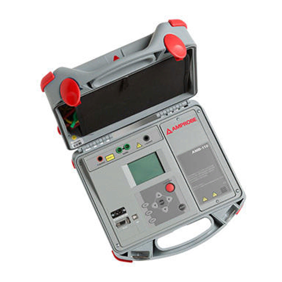
- Page 4 AMB-110 10000V Insulation Resistance Tester Battery Display cover START/STOP key to start or stop any measurement. ON/OFF key to switch the instrument ON or OFF. MEM key to store, recall and erase results. SELECT key to enter set-up mode for the selected function or to select the active parameter to be set.
-
Page 5: Table Of Contents
AMB-110 10000V Insulation Resistance Tester CONTENTS SYMBOLS ..............................3 SAFETY INFORMATION ..........................3 MEANING OF SYMBOLS ...........................3 GENERAL PRECAUTIONS ..........................3 BATTERIES ..............................3 EXTERNAL VOLTAGES ..........................4 WORKING WITH THE INSTRUMENT ......................4 HANDLING WITH CAPACITIVE LOADS ....................4 UNPACKING AND INSPECTION ........................4 FEATURES ..............................5 OPERATION ...............................6 Performing measurements ........................6... - Page 6 Usb Communication ..........................35 Clock ..............................35 MAINTENANCE ............................36 Inserting and charging batteries for the first time ................36 Replacing and charging batteries ......................36 Cleaning ..............................37 Calibration ............................37 AMB-55 AND AMB-110 PC SOFTWARE INSTRUCTION MANUAL ............38 GlobalTestSupply www. .com Find Quality Products Online at: sales@GlobalTestSupply.com...
-
Page 7: Symbols
SYMBOLS Refer to the explanation in this Double Insulated or Reinforced � Manual insulation Risk of electric shock Earth Ground Alternating Current Fuse � Direct Current Complies with EU directives Do not dispose of this product as Conform to relevant Australian �... -
Page 8: External Voltages
• Never touch the measured object during the testing until it is totally discharged. • Maximum external voltage between any two leads is 600 V (CAT IV environment). UNPACKING AND INSPECTION Your shipping carton should include: AMB-110 Meter Test Leads Aligator Clips (Red, Black, Green) Power Supply Cord Set... -
Page 9: Features
FEATURES This Tester is a portable battery / mains powered test instrument intended for the testing of Insulation Resistance by using high test voltages of up to 10kV. The instrument is designed and produced with the extensive knowledge and experience acquired through many years of of working in this sector. -
Page 10: Operation
Auto-calibration prevents the reduction in accuracy when measuring very low currents. It compensates the effects caused by ageing, temperature and humidity changes etc. A new auto-calibration is recommended when the temperature changes by more than 5 °C. AMB-110 10kV Fig. 1 First introduction Fig. 2 Auto-calibration Fig. -
Page 11: Mains Powered Instrument Operation
Mains powered instrument operation If you connect instrument to the mains supply when instrument is turned OFF, internal charger will begin to charge the batteries but instrument will remain turned OFF. In button left angle of LCD, flashing battery indicator will appear to indicate that the batteries are charging. Note: If batteries are defective or missing, the charger will not work. -
Page 12: To Clear All Memory Locations
To clear all memory locations: 1. Select Configuration from the main menu 2. Highlight the Memory Clear option using and arrows. 3. Press the SELECT key, (“Press MEM to confirm!” message will be displayed). 4. Press the MEM key to clear all memory locations or ESC to cancel the activity. Fig. -
Page 13: Dc Vs. Ac Testing Voltage
DC vs. AC testing voltage Testing with a DC voltage is widely accepted as being useful as testing with AC and / or pulsed voltages. DC voltages can be used for breakdown tests especially where high capacitive leakage currents interfere with measurements using AC or pulsed voltages. DC is mostly used for insulation resistance measurement tests. -
Page 14: Basic Insulation Resistance Test
Itest C i s o R i s o R i s s Fig. 6 The Fig. 6 shows typical currents for that circuit. = overall test current (I test test RISO RISS = polarization absorption current = actual insulation current RISO = surface leakage current RISS... -
Page 15: Polarisation Index
POLARISATION INDEX The purpose of this diagnostic test is to evaluate the influence of the polarization part of insulation (Rpi, Cpi). After applying a high voltage to an insulator the electric dipoles distributed in the insulator align themselves with the applied electrical field. This phenomenon is called polarization. As the molecules polarize, a polarization (absorption) current lowers the overall insulation resistance of the material. -
Page 16: Withstanding Voltage Test
Withstanding voltage test Some standards allow the use of a DC voltage as an alternative to AC withstanding voltage testing. For this purpose the test voltage has to be present across the insulation under test for a specific time. The insulation material only passes if there is no breakdown or flash over. Standards recommend that the test starts with a low voltage and reaches the final test voltage with a slope that keeps the charging current under the limit of the current threshold. -
Page 17: Filter Options
where: Ut ... Test voltage IL .... Leakage current (resulted by surface dirt and moisture) IM ... Material current (resulted by material conditions) IA.... A-meter current • Result without using GUARD terminal: RINS = Ut / IA = Ut / (IM + IL) …incorrect result. •... -
Page 18: Example
Example: • A noise current of 1 mA / 50 Hz adds approximately 15 % distribution to the measured result when measuring 1 GOhm • By selecting FIL1 option the distribution will reduce to less than 2 %. • In general using FIL2 and FIL3 will further improve the noise reduction. Voltage measurement Selecting this function displays the following states (initial state and state with results after completion of the measurement, see the Fig. -
Page 19: Measurement Procedure
The Fig. 10 shows states when Graph R(t) is enabled. After taking a measurement, you can switch back and forth between numerical mode display and graphical mode display by pressing or keys. graphical mode numerical mode Note • It is not possible to switching mode of presentation when measurement running!!! Initial display - Display with results - numerical mode... -
Page 20: Setting Up Parameters For Insulation Resistance
Displayed symbols: INSULATION RESISTANCE Name of selected function Off fil0 (Fil1, Fil2, Fil3) Filter type enabled, see the section of Configuration 5000V Set test voltage U=5323V Actual test voltage – measured value I=266nA Actual test current – measured value 19.9Ge Insulation Resistance –... -
Page 21: Enable/Disable The Graph R(T) And Set-Up The Graph R(T) Parameters In The Insulation Resistance Function
Displayed symbols: INSULATION RESISTANCE Name of selected function SETTING PARAMETERS: Unominal 5000 V Set test voltage –25 V steps Timer 5min 00s Duration of the measurement Timer on/off ON: timer enabled, OFF: timer disabled Time1 01min 00s Time to accept and display first Rmin and Rmax results Graph R(t) Enable/Disable Graph R(t) Timer and Time1 are independent timers. -
Page 22: Diagnostic Test
Diagnostic test Selecting this function displays the following states (initial state and state with results after the completion of the measurement). The Fig. 14 shows states when Graph R(t) is disabled. Initial display – numerical mode Display with results – numerical mode Fig. -
Page 23: Dielectric Absorption Ratio (Dar)
DIELECTRIC ABSORPTION RATIO (DAR) DAR is ratio of Insulation Resistance values measured after 15s and after 1 minute. The DC test voltage is present during the whole period of the test (also an Insulation Resistance measurement is continually running). At the end, the DAR ratio is displayed: Some applicable values: DAR value Tested material status... -
Page 24: Dielectric Discharge Testing (Dd)
Note • When determining Riso (1min) pay close attention to the capacitance of the object under test. It has to be charged-up in the first time section (1 min). Approximate maximum capacitance using: where: t ....period of first time unit (e.g. 1min) U .... -
Page 25: Setting Up The Parameters Of The Diagnostic Test
Displayed symbols: DIAGNOSTIC TEST Name of selected function Fil0 (Fil1, Fil2, Fil3) Filter type enabled, see the section of Configuration 5000V Set test voltage – step 25 V U=5295 Actual test voltage – measured value I=55.6nA Actual test current – measured value 10.5Ge Insulation Resistance –... -
Page 26: Enable/Disable The Graph R(T) And Set-Up The Graph R(T) Parameters In The Diagnostic Test Function
DD on/off ON: DD enabled, OFF: DD disabled Graph R(t) Enable/Disable Graph R(t) Time1, Time2 and Time3 are timers with the same start point. The value of each presents the duration from the start of the measurement. The maximum time is 99 min. The following Fig.17 shows the timer relationships. -
Page 27: Step Voltage Insulation Resistance Testing
Step Voltage Insulation Resistance testing Selecting this function displays the following states (initial state and state with results after the completion of the measurement). The Fig. 20 shows states when Graph R(t) is disabled. Initial display Display with results Fig. 20 Step Voltage function display states - Graph R(t) enabled The Fig.21 shows states when Graph R(t) is enabled. -
Page 28: Measurement Procedure
In this test, the insulation is measured in five equal time periods with test voltages from one fifth of the final test voltage up to full voltage (see the Fig. 22). This function illustrates the relationship of a materials Insulation resistance and its applied voltage. Measurement procedure: •... -
Page 29: Setting Up The Parameters Of The Diagnostic Test
• A high-voltage warning symbol appears on the display during the measurement to warn the operator of a potentially dangerous test voltage. • The value of capacitance is measured during the final discharge of test object. Setting up the parameters of the Diagnostic Test: •... -
Page 30: Withstanding Voltage
�Warning! • Refer to Warnings chapter for safety precautions! Withstanding voltage This function offers Withstanding Voltage test of insulation material. It covers two types of tests: a) Breakdown voltage testing of high voltage device, e.g. transient suppressors and b) DC withstanding voltage test for insulation coordination purposes. Both functions require breakdown current detection. -
Page 31: Measuring Procedure
Displayed symbols: WITHSTANDING VOLTAGE DC Name of selected function 2000V Start test voltage 7000V Stop test voltage 7221V Actual test voltage – measured value I=0.002mA Actual test current – measured value tm:01min 00s Timer information Measuring procedure: • Connect the test leads to the instrument and to the measured object. •... -
Page 32: Working With Your Results
Fig. 28 Set-up menu in Withstanding Voltage function Tstep and Tend are independent timers. The maximum time for each timer is 99 minutes. Tend begins after the completion of the ramp period. Ramp period can be calculated from: Tramp Tstep . (Ustop – Ustart) / 25 V If Tstep is set to 00min 00s, then the ramp voltage increases by approximately 25 V every 2s. - Page 33 Recall measurement without the graph R(t): Recall: 0006 Recall measurement with the graph R(t): Recall: 0007 G “0006” and “0007” represents the serial number of the stored results. G letter means the graph R(t), if added. Results can be scrolled through by using the and keys. To see the Graph R(t) press the SELECT key, to go back to the numerical measurement result press the ESC key.
- Page 34 Function name Last measured insulation resistance Set test voltage Actual test voltage - measured value Actual test current - measured value Capacitance of the tested object Duration of the complete test Insulation Resistance value taken afterT1 Diagnostic test Insulation Resistance value taken afterT2 Insulation Resistance value taken afterT3 DAR value PI value...
-
Page 35: Transferring Data To A Pc
Note • *Date and time of storing the test result are transferred to PC while date and time of recalling are displayed when recalling results. TRANSFERRING DATA TO A PC Stored results can be transferred to a PC. The communication program can identify the instrument and download the data. - Page 36 Measuring range Riso: 0.12 Me up to 10 Te*) Display range Riso Resolution Accuracy 0 - 999 ke 1 ke 1.00 - 9.99 Me 10 ke 10.0 - 99.9 Me 100 ke 100 - 999 Me 1 Me (5 % of reading + 3 digits) 1.00 - 9.99 Ge 10 Me 10.0 - 99.9 Ge...
- Page 37 Generator Capability vs Resistance 0. 1 Ut est = 10kV Ut est = 5kV Electric absorption ratio DAR Display range DAR Resolution Accuracy 0.01 - 9.99 0.01 (5% of reading + 2digits) 10.0 - 100.0 (5% of reading) Polarization index PI Display range PI Resolution Accuracy...
- Page 38 Withstanding voltage DC • DC test voltage: • Voltage value: Any value within 500V and 10kV. • Accuracy: -0 / +10 % + 20 V. Display range Test voltage (V) Resolution Accuracy 0 - 9999 V (3 % of reading + 3 V) 10 kV 0,1 kV (3 % of reading)
-
Page 39: General Specifications
GENERAL SPECIFICATIONS Battery power supply 7.2 V DC (6 × 1.2V Ni-MH; IEC LR20) • Mains power supply : 90-260 V AC, 45-65 Hz, 60 VA / (300V CAT III) • Protection classification : double insulation • Over-voltage category : CAT IV 600 V •... -
Page 40: Maintenance
MAINTENANCE Inserting and charging batteries for the first time Battery cells are stored in the bottom section of the instrument casing under the battery cover (see Fig. 30). When inserting batteries for the first time please note the following: • Disconnect any measurement accessories or mains supply cable connected to the instrument before opening the battery cover to avoid electric shock. -
Page 41: Cleaning
Fig. 30 Correct polarity of inserted batteries Ensure batteries are used and disposed of in accordance with Manufacturers guidelines and in accordance with Local and National Authority guidelines! Cleaning Use a soft cloth, slightly moistened with soapy water or spirit to clean the surface of the instrument and leave the instrument to dry totally before using it. -
Page 42: Amb-55 And Amb-110 Pc Software Instruction Manual
• The pop-up windows will guide you through the program setup process. INTRODUCTION AMBLink PRO program is a PC Software for AMB-55 and AMB-110 instruments. It is intended for downloading data from the instrument to PC and review downloaded data as a table or graph. The functionality for downloading is connected to the password, that is unique for instrument’s serial number. - Page 43 Language: enables you to select different program languages if there are more than one available. Password: enables you to add or remove password for communication with AMB-55 and AMB-110 instruments. You can add more different passwords to use only one PCSW for communication with more instruments.
- Page 44 USING PROGRAM Structure Editor Structure editor enables you to edit a structure and belonging measurements. You can delete items, change its settings (name), move subitems (measurements) from one item to another (move toolbutton should be in up position ) and move items up and down within its parent item (move toolbutton should be in down position When you drag item over another, the frame of the item is colored red, green or blue.
- Page 45 Structure Editor File presentation consists of structure tree and setting field on the left side and results table on the right side of the screen. Setting properties are connected to the selected item from the structure tree. It is possible to change Item name. Results are connected to the selected item from the structure tree.
- Page 46 Graph Graph command enables you to Print and Close graph. View command enables you Auto Range, Restore Range and Refresh Data. Print: prints graph Close: closes graph Auto Range: sets maximal value of Resistance X axis to optimal value due to max. resistance value. Restore Range: sets maximal value of Resistance X axis to original value.
- Page 47 Table Table command enables you to Print and Close table. Print: prints table. Close: closes table. Measurement table represents 12 points of measurement graph. Table data belongs to time 15sec, 30sec and 1min to 10min time. If the data at specific time is not available, 5s plus or minus is taken into account. Functionality is available for all different measuring functions, except for STEP VOLTAGE.
- Page 48 Print Header (Header, Comment, Footer) 1. Report header appears at the beginning of the first page of PRO report. There are five fields to define: • Operator (the person who performed tests), • Test site (location where tests were performed), •...
- Page 49 Report print preview Report print preview form shows measured results in PRO REPORT form completed with Report header, Report comments and Page footer. This is the form that will appear on the printed PRO report. From print preview window you can set up printer and print PRO report by clicking on the appropriate icon Export Format of the text file is defined in the Export Format window that is shown automatically after selecting File / Export from Main Menu command of Main Screen.
- Page 50 GlobalTestSupply www. .com Find Quality Products Online at: sales@GlobalTestSupply.com...
Need help?
Do you have a question about the AMB-110 and is the answer not in the manual?
Questions and answers