Advertisement
Quick Links
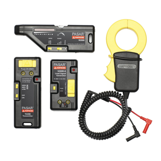
The AT-2000-A series consists of individual components with unique capabilities. This label describes the capabilities
of the complete system (AT-2005-A). Any other system in this series can be upgraded to include all of these
capabilities by simply purchasing the additional components.
CAUTION: Always verify that the voltage presence is not beyond the range of the instrument. 300V Max
Identifying Circuit Breakers
Use R2000 & S2600-A (LSGs)
1. For 110V receptacle, connect pigtail cordset to LSG and plug into receptacle; for other voltages or connections,
use the Alligator-clip cordset.
2. The light will blink if connection is
correct.
3. Set the R2000's range to x1; mode to
'SHORT', and thumbwheel to around 5.
4. Hold R2000 near LSG to verify its
operation.
5. At the breaker panel, pass the R2000
over the load side of each breaker,
always reducing the sensitivity when
more than 9 LEDs are lit.
6. The strongest signal indicates the
proper breaker.
Locating Ground Faults
A ground fault is a direct connection of the conductor to ground. A typical ground fault may cause a tripped circuit
breaker or a blown fuse ( in contrast to an 'open', which passes no current). In this situation, the B2024 battery
can be used as the current source. The high voltage from the B2024 will overcome a high resistance fault and will
produce a stronger signal. Also, you can use line voltage as the power source by connecting the S2600-A across the
breaker.
LSG
Amprobe
®
www.Amprobe.com
info@amprobe.com
Everett, WA 98203
Tel: 877-AMPROBE (267-7623)
Advanced Wire Tracer
Fig. 2 Locating
Ground Faults
Amprobe
®
Europe
Beha-Amprobe
In den Engematten 14,
79286 Glottertal, Germany
Tel.: +49 (0) 7684 8009 - 0
Fig. 1 Identifying Circuit Breakers
R2000
LSG
Use R2000 & S2600-A (LSGs)
1. Plug the alligator clip cordset into the
LSG and connect one clip to ground.
2. Connect the other clip to one terminal
of a battery (at least 9V).
3. Using a separate jumper, connect the
other battery terminal to the faulted
wire.
4. Set the R2000 to the 'SHORT' mode
and adjust the sensitivity and range
switch until 8–9 LEDs are displayed.
5. Trace the wire. The fault will be at the
point where you begin to lose the
signal.
©2013 Amprobe
AT-2000-A Series
OR
LSG
P/N 2757342 Rev 002
11/2013 6001648 A
®
Test Tools. All rights reserved.
Advertisement

Related Manuals for Amprobe AT-2000-A Series


Summary of Contents for Amprobe AT-2000-A Series
- Page 1 AT-2000-A Series Advanced Wire Tracer The AT-2000-A series consists of individual components with unique capabilities. This label describes the capabilities of the complete system (AT-2005-A). Any other system in this series can be upgraded to include all of these capabilities by simply purchasing the additional components.
- Page 2 Locating Opens Fig. 3 Tracing Open Wires Use the R2000 & T2200 1. Plug the alligator clip cordset into the T2200 and attach one clip to a separate R2000 ground and the other to the wire. 2. Where possible, ground any adjacent wires.
Need help?
Do you have a question about the AT-2000-A Series and is the answer not in the manual?
Questions and answers