Table of Contents
Advertisement
Quick Links
D
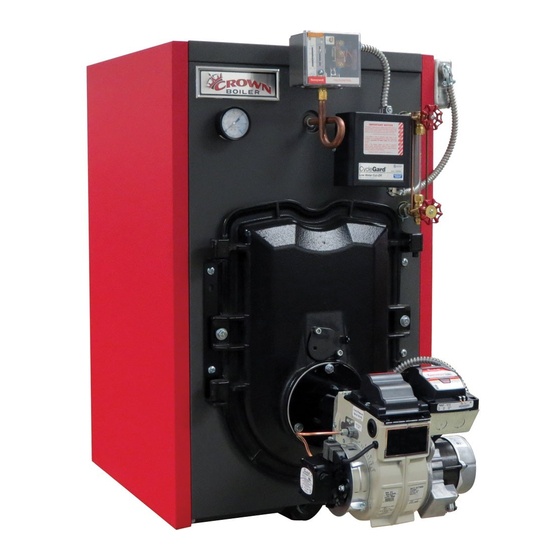
FSZ Series
Oil-Fired Steam Boilers
InStallatIOn InStructIOnS
These instructions must be affixed on or adjacent to the boiler
Models:
FSZ080
•
FSZ100
•
FSZ130
•
FSZ160
•
E S I G N E D
Warning: Improper installation,
adjustment, alteration, service or
maintenance can cause property
damage, injury, or loss of life.
For assistance or additional
information, consult a qualified
installer, service agency or the oil
supplier. Read these instructions
carefully before installing.
Manufacturer of Hydronic Heating Products
P.O. Box 14818 3633 I. Street
Philadelphia, PA 19134
www.crownboiler.com
L
T O
E A D
Advertisement
Table of Contents

Related Manuals for Crown Boiler FSZ080


Summary of Contents for Crown Boiler FSZ080
-
Page 1: Installation Instructions
E S I G N E D E A D FSZ Series Oil-Fired Steam Boilers InStallatIOn InStructIOnS These instructions must be affixed on or adjacent to the boiler Models: FSZ080 • Warning: Improper installation, FSZ100 • adjustment, alteration, service or FSZ130 maintenance can cause property •... - Page 3 WARNINGS FOR THE HOMEOWNER FOLLOW ALL INSTRUCTIONS and warnings unless alarms or other safeguards are in place to printed in this manual and posted on the boiler. prevent such damage INSPECT THE BOILER, BURNER AND DO NOT BLOCK AIR FLOW into or around the CONTROLS ANNUALLY.
-
Page 4: Table Of Contents
table of contents Product Description ................3 Specifications ..................3 III. Before Installing ..................5 Field Assembly ..................6 Locating the Boiler ................7 Air for Combustion & Ventilation ............8 VII. Venting ....................13 VIII. System Piping ..................15 Indirect &... -
Page 5: Product Description
WATER CONTENT (TO NORMAL DIMENSIONS HEAT TRANSFER SHIPPING WATER LINE) (GALLONS) BOILER SURFACE AREA WEIGHT MODEL WITH TANKLESS (SQ FT) (LBS) ‘A’ ‘B’ ‘C’ NON-HEATER HEATER FSZ080 22-1/4” 24” 6” 15.3 14.9 20.29 FSZ100 22-1/4” 24” 6” 15.3 14.9 20.29 FSZ130 28-1/4” 30”... -
Page 7: Before Installing
Crown Boiler Company recommends the use of a chimney to vent the FSZ series boilers. If a power venter must be used, it is the responsibility of the installer and power vent manufacturer to “engineer”... -
Page 8: Field Assembly
IV Field assembly This boiler is shipped in two pieces: a) The crated boiler itself b) The burner carton consisting of the following items: • Oil Burner assembly • Barometric Draft Regulator (if supplied) • Safety valve • Drain valve •... -
Page 9: Locating The Boiler
V locating the Boiler WARNING Failure to observe the following location requirements could result in property damage, a fire, explosion or carbon monoxide (CO) hazard. 1) Clearances: • Observe the minimum clearances shown below. Except as noted, these clearances apply to all combustible construction, as well as noncombustible walls, ceilings and doors. -
Page 10: Air For Combustion & Ventilation
1) Do not install this boiler directly on a combustible floor. Where it is desired to install an FSZ on a non-carpeted combustible floor, install the boiler on a base constructed as shown in Figure 5.1 2) If listed Type L vent is used, follow vent pipe manufacturer recommendations for minimum clearances. 3) Do not install this boiler in a location where gasoline or other flammable vapors or liquids will be stored or used. - Page 11 Example: An FSZ080 and a water heater are to be installed in a room measuring 6 ft - 3 in x 7 ft with an 8 ft ceiling. The water heater has an input of 30000 BTU/hr: Input of FSZ080 = 0.80 Gal/hr x 140000 BTU/Gal = 112000BTU/hr...
- Page 12 FIGurE 6.0: BOIlEr InStallED In cOnFInED SPacE, all aIr FrOM InSIDE FIGurE 6.1: all aIr FrOM OutDOOrS, VEntIlatED craWl SPacE anD attIc...
- Page 13 FIGurE 6.2: all aIr FrOM OutDOOrS, VIa VEntIlatED attIc FIGurE 6.3: all aIr FrOM OutDOOrS, uSInG OPEnInGS IntO BOIlEr rOOM...
- Page 14 FIGurE 6.4: all aIr FrOM OutDOOrS, uSInG HOrIZOntal DuctS IntO BOIlEr rOOM...
-
Page 15: Venting
VII Venting WARNING • Improper venting may result in property damage and/or the release of flue gases, which contain deadly carbon monoxide (CO), into the home, which can cause severe personal injury or death. • Inspect existing chimney before installing boiler. Failure to clean or replace damaged pipe or tile lining will cause property damage, severe personal injury or death. - Page 16 7.1: MInIMuM rEcOMMEnDED BrEEcHInG anD cHIMnEY SIZE MINIMUM CHIMNEY REQUIREMENTS MINIMUM BOILER BREECHING MODEL ROUND I.D. SQUARE. TILE DIA. (INCHES) HEIGHT (FT.) (IN.) SIZE (NOMINAL) FSZ080 8 X 8 FSZ100 8 X 8 FSZ130 8 X 8 FSZ160 8 X 8...
-
Page 17: System Piping
VIII System Piping WARNING • Install boiler so that the electrical components are protected from water (dripping, spraying, rain, etc.) During appliance operation and service (circulator replacement, etc.). • Operation of this boiler in a system having significant amounts of dissolved oxygen can cause severe heat exchanger corrosion damage. -
Page 19: Piping Installation
FIGurE 8.2: nEar BOIlEr PIPInG MIStaKES Piping Installation 1) Remove parts bag from boiler crate. 2) Install safety valve as shown in Figure 8.1 into the 3/4” tapping “F” on rear of the boiler (spindle must be in vertical position). 3) Pipe the discharge of the safety relief valve to a location where water or steam will not create a hazard or cause property damage if the valve opens. - Page 20 1/2” Water Gauge Glass 2” Supply (Front & Rear Tappings) 3/4” Safety Valve Condensate Return (Reduced to 1-1/4” 1-1/2” on FSZ080,100 & 130) 1-1/4” Optional Front Return (Plugged) 1-1/2” Surface Blowoff (Plugged) 1” Indirect Water Heater Supply (Plugged) 1/2” Indirect Water Heater Limit (Plugged) L4006 Operating 1/2”...
-
Page 21: Indirect & Tankless Water Heater Piping
IX InDIrEct & tanKlESS WatEr HEatEr PIPInG InDIrEct WatEr HEatEr PIPInG All FSZ series boilers are equipped with tappings to permit the connection of a Crown Mega-Stor, or other indirect water heater. In this type of system, hot boiler water is drawn from below the water line and passed through the heat exchanger in the indirect water heater. -
Page 22: Tankless Heater Piping
IMPOrtant • Some indirect water heaters may not be suitable for use with a steam boiler. Consult the water heater manufacturer’s guidelines before installing it in this type of system. • Boiler water temperatures and flow rates in this type of system may be considerably lower than those upon which the water heater manufacturer’s ratings are based. - Page 23 6) Unions (Required) - Tankless heaters may require periodic gasket replacement or other maintenance which requires removal of the heater from the boiler. Install unions anywhere in the tankless heater piping that will facilitate removal of the heater. FIGurE 9.2: tanKlESS HEatEr PIPInG...
-
Page 24: Fuel Line Piping
X Fuel line Piping WARNING • Under no circumstances can copper with sweat style connectors be used. • Do not use compression fittings. • Oil piping must be absolutely airtight or leaks or loss of prime may result. • Some jurisdictions require the use of a fusible shutoff valve at the tank and/or the burner. In addition, some jurisdictions require the use of a fusible electrical interlock with the burner circuit. - Page 25 10) All systems require an oil filter. Use of a high efficiency micron filter (Garber or equivalent) in addition to a conventional filter is highly recommended, particularly on the FSZ080. 11) Use only #2 Fuel Oil with physical and chemical characteristics meeting the requirements of ASTM D-396.
- Page 26 FIGurE 10.2: tWO-PIPE GraVItY FEED SYStEM (nOt rEcOMMEnDED) FIGurE 10.3: tWO-PIPE lIFt SYStEM...
-
Page 27: Wiring
XI Wiring WARNING • All wiring and grounding must be done in accordance with the authority having jurisdiction or, in the absence of such requirements, with the National Electrical Code (ANSI/NFPA 70). • Disconnect electrical power to the boiler and heating system before servicing. Positively assure that no voltage is present. -
Page 28: Thermostat Wiring
Indirect Water Heater Wiring Figure 11.2 shows field wiring for an indirect water heater. A Honeywell R845A or equivalent DPST relay and transformer is required. The high limit described in Part VIII must also be supplied by the installer. A call for heat from the indirect water heater thermostat will energize the relay making both sets of contacts. - Page 30 FIGurE 11.1: cOnnEctIOnS WIrInG DIaGraM FOr BurnEr SPEcIFIc PrIMarY cOntrOl...
- Page 31 FIGurE 11.2: InDIrEct WatEr HEatEr FIElD WIrInG...
-
Page 32: Start-Up & Checkout
XII Start-up and checkout WARNI NG • Never attempt to fill a hot empty boiler. • Make sure that the area around the boiler is clear and free from combustible materials, gasoline, and other flammable vapors and liquids. • Safe reliable operation of this boiler requires that the burner be checked and adjusted by a qualified oil serviceman using combustion test instruments. - Page 33 FIGurE 12.0: FluE DraFt taPPInG 17) Check the vacuum at the inlet of the fuel pump. Make sure that the vacuum does not exceed the fuel pump manufacturer’s limit (consult the pump manufacturer’s instructions). 18) Close the flame observation cover. 19) After chimney has warmed-up for at least 5 minutes, adjust barometric draft regulator to obtain a draft at the 1/4”...
- Page 34 the boiler with owner or in boiler room, displayed near boiler. 30) After new boiler has been installed and put into continuous operation for several days, clean the boiler of oil, grease, sludge, and other contaminants that may have been present in existing piping. This will prevent unsteady water line and water carry over into supply main.
- Page 35 12.1a: BEcKEtt BurnEr cOnFIGuratIOn anD SEtuP Data BOILER MODEL FSZ080 FSZ100 FSZ130 FSZ160 BURNER MODEL AIR TUBE COMBO 70MMAQN 70MMAQN 70MLASN 70MLASN HEAD TYPE STATIC PLATE 3-3/8U 3-3/8U NONE 2-3/4M Beckett Silver LOW FIRING RATE BAFFLE NONE NONE NONE...
-
Page 36: Service & Maintenance
XIII Service and Maintenance a. Water Side Maintenance the following procedure should be performed on an annual basis: 1) Turn off electrical power and oil supply to the boiler. 2) Inspect the low water cut-off: • For Hydrolevel CG450 low water cut-offs - Remove and inspect the probe for scale and sediment buildup. Clean any sediment or scale from the probe with a scouring pad or steel wool. - Page 37 B. Fire Side Maintenance WARNING All boiler cleaning must be completed with the burner service switch turned off. Boilers equipped with burner swing door have a potential hazard which can cause severe property damage, personal injury or loss of life if ignored. Before opening swing door, turn off service switch to boiler to prevent accidental firing of burner outside the combustion chamber.
- Page 38 WARNING The boiler must be connected to an approved chimney in good condition. Serious property damage could result if the boiler is connected to a dirty or inadequate chimney. The interior of the chimney flue must be inspected and cleaned before the start of the heating season and should be inspected periodically throughout the heating season for any obstructions.
- Page 39 Important Product Safety Information Refractory Ceramic Fiber Product Warning: The Parts list designates parts that contain refractory ceramic fibers (RCF). RFC has been classified as a possible human carcinogen. When exposed to temperatures about 1805°F, such as during direct flame contact, RFC changes into crystalline silica, a known carcinogen.
-
Page 40: Troubleshooting
XIV trouble Shooting a. combustion 1) Nozzles - The selection of the nozzle supplied with the FSZ boiler is the result of extensive testing to obtain the best flame shape and efficient combustion. Other brands of the same spray angle and pattern may be used but may not perform at the expected level of CO2 and smoke. - Page 41 notes...
-
Page 42: Parts
XV Parts QUANTITY PER BOILER OR CROWN PART NUMBER QTY. OR KEY # DESCRIPTION CROWN PN FSZ080 FSZ100 FSZ130 FSZ160 HEAT EXCHANGER ASSEMBLY WITH 420013 420013 420014 420015 HEATER OPENING HEAT EXCHANGER ASSEMBLY WITH NO 4200135 4200135 4200145 4200155 HEATER OPENING... - Page 44 QUANTITY PER BOILER OR CROWN PART NUMBER QTY. OR KEY # DESCRIPTION CROWN PN FSZ080 FSZ100 FSZ130 FSZ160 RECEPTACLE ENCLOSURE 410090 FRONT JACKET PANEL 420310 RIGHT SIDE JACKET PANEL 420303 420303 420304 420305 LEFT SIDE JACKET PANEL 420313 420313 420314...
- Page 46 QUANTITY PER BOILER OR CROWN PART NUMBER QTY. OR KEY # DESCRIPTION CROWN PN FSZ080 FSZ100 FSZ130 FSZ160 BECKETT OIL BURNER ASSY (NOTE 1) 42080B 42100B 41130B 41160B RIELLO OIL BURNER ASSY (NOTE 1) 42080R 42100R 41130R 41160R HONEYWELL R8285D5001 W/ MOLEX CONNECTOR...
-
Page 48: Appendix A. Installation Of Optional Gravity Return Piping Kit
421096 - Dropped Header Gravity Return Near Boiler Piping Kit (FSZ160) These kits provide the pipe and fittings needed for the “drop header” piping as listed in Table A.1 for the FSZ080, FSZ100 and FSZ130 and in Table A.3 for the FSZ160. - Page 49 Dropped Header Material list for FSZ080, FSZ100 and FSZ130 Boilers Item Fitting Description Quantity 2” x 12” Nipple 2” Union 2” x 6” Nipple 2” Elbow 2” x 15” Nipple 2” x 7” Nipple 2” x 3” Nipple (FSZ080 and FSZ100) 2”...
- Page 50 taBlE a-3: Dropped Header Material list for FSZ160 Boilers Item Fitting Description Quantity 2” x 12” Nipple 2” Union 2” x 6” Nipple 2” Elbow 2” x 15” Nipple 2” x 7” Nipple 3” x 2” Reducing Elbow 3” x 9” Nipple 3”...
- Page 51 notes...
- Page 52 Manufacturer of Hydronic Heating Products P.O. Box 14818 3633 I. Street Philadelphia, PA 19134 www.crownboiler.com PN: 980265 Rev 3 - 07/13...
Need help?
Do you have a question about the FSZ080 and is the answer not in the manual?
Questions and answers