Crown Boiler FWZ060 Installation Instructions Manual
Fwz series oil-fired hot water boilers
Hide thumbs
Also See for FWZ060:
- Installation instructions manual (52 pages) ,
- Installation instructions manual (56 pages)
Table of Contents
Advertisement
D
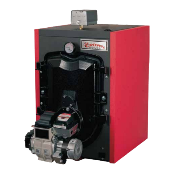
FWZ Series
Oil-Fired Hot Water Boilers
InstallatIOn InstructIOns
These instructions must be affixed on or adjacent to the boiler
Models:
FWZ060
•
FWZ080
•
FWZ100
•
FWZ130
•
FWZ160
•
E S I G N E D
Warning: Improper installation,
adjustment, alteration, service or
maintenance can cause property
damage, injury, or loss of life.
For assistance or additional
information, consult a qualified
installer, service agency or the oil
supplier. Read these instructions
carefully before installing.
Manufacturer of Hydronic Heating Products
P.O. Box 14818 3633 I. Street
Philadelphia, PA 19134
www.crownboiler.com
L
T O
E A D
1
Advertisement
Table of Contents

Related Manuals for Crown Boiler FWZ060


Summary of Contents for Crown Boiler FWZ060
-
Page 1: Installation Instructions
E S I G N E D E A D FWZ Series Oil-Fired Hot Water Boilers InstallatIOn InstructIOns These instructions must be affixed on or adjacent to the boiler Models: FWZ060 • FWZ080 Warning: Improper installation, • adjustment, alteration, service or FWZ100 •... - Page 3 WARNINGS FOR THE HOMEOWNER FOLLOW ALL INSTRUCTIONS and warnings unless alarms or other safeguards are in place to printed in this manual and posted on the boiler. prevent such damage INSPECT THE BOILER, BURNER AND DO NOT BLOCK AIR FLOW into or around the CONTROLS ANNUALLY.
-
Page 4: Table Of Contents
table of contents Product Description ................3 Specifications ..................3 III. Before Installing ..................5 Field Assembly ..................6 Locating the Boiler ................7 Air for Combustion & Ventilation ............8 VII. Venting ....................13 VIII. System Piping ..................15 Fuel Line Piping .................. -
Page 5: Product Description
II Specifications taBlE 2.0: GEnEral sPEcIFIcatIOns DIMENSIONS WATER HEAT TRANSFER SHIPPING BOILER CONTENT SURFACE AREA WEIGHT MODEL ‘A’ ‘B’ ‘C’ (GAL) (SQ FT) (LBS) FWZ060 16-1/4” 24” 5” 7.70 13.29 FWZ080 16-1/4” 24” 5” 7.70 13.29 FWZ100 22-1/4” 24” 6” 11.08 20.29... -
Page 7: Before Installing
Crown Boiler Company recommends the use of a chimney to vent the FWZ series boilers. If a power venter must be used, it is the responsibility of the installer and power vent manufacturer to “engineer”... -
Page 8: Field Assembly
IV Field assembly This boiler is shipped in two pieces: a) The crated boiler itself with the following loose parts either packed in the combustion chamber or glued to the skid: • Barometric Draft Regulator (if supplied) • Circulator (if supplied) •... -
Page 9: Locating The Boiler
V locating the Boiler WARNING Failure to observe the following location requirements could result in property damage, a fire, explosion or carbon monoxide (CO) hazard. 1) Clearances: • Observe the minimum clearances shown below. Except as noted, these clearances apply to all combustible construction, as well as noncombustible walls, ceilings and doors. -
Page 10: Air For Combustion & Ventilation
1) Do not install this boiler directly on a combustible floor. Where it is desired to install an FWZ on a non-carpeted combustible floor, install the boiler on a base constructed as shown in Figure 5.1 2) If listed Type L vent is used, follow vent pipe manufacturer recommendations for minimum clearances. 3) Do not install this boiler in a location where gasoline or other flammable vapors or liquids will be stored or used. - Page 11 a. For Buildings of Other than unusually tight construction 1) Determine whether the boiler is to be installed in a confined space - A confined space is defined as having a volume less than 50 cubic feet per 1000 BTU/hr input of all appliances installed in that space. To determine whether the boiler room is a confined space: a) Total the input of all appliances in the boiler room in thousands of BTU/hr.
- Page 12 FIGurE 6.0: BOIlEr InstallED In cOnFInED sPacE, all aIr FrOM InsIDE FIGurE 6.1: all aIr FrOM OutDOOrs, VEntIlatED craWl sPacE anD attIc...
- Page 13 FIGurE 6.2: all aIr FrOM OutDOOrs, VIa VEntIlatED attIc FIGurE 6.3: all aIr FrOM OutDOOrs, usInG OPEnInGs IntO BOIlEr rOOM...
- Page 14 FIGurE 6.4: all aIr FrOM OutDOOrs, usInG HOrIZOntal Ducts IntO BOIlEr rOOM...
-
Page 15: Venting
VII Venting WARNING • Improper venting may result in property damage and/or the release of flue gases, which contain deadly carbon monoxide (CO), into the home, which can cause severe personal injury or death. • Inspect existing chimney before installing boiler. Failure to clean or replace damaged pipe or tile lining will cause property damage, severe personal injury or death. - Page 16 7.1: MInIMuM rEcOMMEnDED BrEEcHInG anD cHIMnEY sIZE MINIMUM CHIMNEY REQUIREMENTS MINIMUM BOILER BREECHING MODEL ROUND I.D. SQUARE. TILE DIA. (INCHES) HEIGHT (FT.) (IN.) SIZE (NOMINAL) FWZ060 8 X 8 FWZ080 8 X 8 FWZ100 8 X 8 FWZ130 8 X 8 FWZ160 8 X 8...
-
Page 17: System Piping
VIII system Piping WARNING • Install boiler so that the electrical components are protected from water (dripping, spraying, rain, etc.) During appliance operation and service (circulator replacement, etc.). • Operation of this boiler with continuous return temperatures below 135°f can cause severe boiler or chimney damage. - Page 18 8.0 Minimum Flow rate requirements Minimum Flow Flow at 20F Rise (Approx 35F Rise) Min. Flow Boiler Head Flow Boiler Head Model (Gal /Min) Loss (ft w.c.) (GPM) Loss (ft w.c.) FWZ060 0.10 0.22 FWZ080 0.16 0.38 FWZ100 0.27 12.3 0.61 FWZ130 10.0 0.42 16.0...
- Page 19 FIGurE 8.1: InstallatIOn OF FactOrY suPPlIED PIPInG FIGurE 8.2: stanDarD BOIlEr PIPInG...
- Page 20 Certain types of heating systems have additional requirements. Some of the more common variations follow: 1) Indirect Water Heaters - Figure 8.3 shows typical indirect water heater piping. Boiler piping is the same as for any two zone system. Figure 8.3 shows circulator zoning, which is usually preferred for indirect water heaters. Size the circulator and indirect water heater piping to obtain the boiler water flow through the indirect water heater called for by the indirect water heater manufacturer.
- Page 21 FIGurE 8.4: BYPass PIPInG FIGurE 8.5: IsOlatIOn OF BOIlEr FrOM sYstEM WItH a HEat EXcHanGEr...
-
Page 22: Fuel Line Piping
IX Fuel line Piping WARNING • Under no circumstances can copper with sweat style connectors be used. • Do not use compression fittings. • Oil piping must be absolutely airtight or leaks or loss of prime may result. • Some jurisdictions require the use of a fusible shutoff valve at the tank and/or the burner. In addition, some jurisdictions require the use of a fusible electrical interlock with the burner circuit. - Page 23 10) All systems require an oil filter. Use of a high efficiency micron filter (Garber or equivalent) in addition to a conventional filter is highly recommended, particularly on FWZ060 and FWZ080. 11) Use only #2 Fuel Oil with physical and chemical characteristics meeting the requirements of ASTM D-396.
- Page 24 FIGurE 9.2: tWO-PIPE GraVItY FEED sYstEM (nOt rEcOMMEnDED) FIGurE 9.3: tWO-PIPE lIFt sYstEM...
-
Page 25: Wiring
X Wiring WARNING • All wiring and grounding must be done in accordance with the authority having jurisdiction or, in the absence of such requirements, with the National Electrical Code (ANSI/NFPA 70). • Disconnect electrical power to the boiler and heating system before servicing. Positively assure that no voltage is present. - Page 26 • Do not attempt to use EnviraCOM connections for any purpose not explicitly permitted by Crown Boiler Company. Attempting to do so may result in unreliable operation and/ or damage to controls. • Do not use the transformer provided on the boiler to power external devices such as...
- Page 27 FIGurE 10.0: WIrInG cOnnEctIOns DIaGraM FOr l7248 aQuastat...
- Page 28 FIGurE 10.1: cOnnEctIOns WIrInG DIaGraM FOr BurnEr sPEcIFIc PrIMarY cOntrOl...
-
Page 29: Start-Up & Checkout
XI start-up and checkout WARNI NG • Never attempt to fill a hot empty boiler. • Make sure that the area around the boiler is clear and free from combustible materials, gasoline, and other flammable vapors and liquids. • Safe reliable operation of this boiler requires that the burner be checked and adjusted by a qualified oil serviceman using combustion test instruments. - Page 30 FIGurE 11.0: FluE DraFt taPPInG 15) Make sure that the oil pressure matches that shown in Table 11.1 for the burner supplied. Adjust pressure if required. 16) Check the vacuum at the inlet of the fuel pump. Make sure that the vacuum does not exceed the fuel pump manufacturer’s limit (consult the pump manufacturer’s instructions).
- Page 31 Attempts to use burners or burner configurations other than those shown in Table 11.1 could result in reliability problems, property damage, personal injury or loss of life taBlE 11.1a: BEcKEtt BurnEr cOnFIGuratIOn anD sEtuP Data BOILER MODEL FWZ060 FWZ080 FWZ100 FWZ130...
-
Page 32: Operation
XII Operation a. General Information This boiler uses a proprietary version of the Honeywell L7248L Aquastat to regulate water temperature and to manage ® demands from up to two circulator zones. Crown offers several options that can be used with this control and which are mounted in a console on top of the boiler. These include a touch screen display, low water cut-off kits, and an outdoor reset control. - Page 33 FIGurE 12.1: BOIlEr cOntrOl MEnu STATUS MODE: =Current Status (Table 12.2) Press and Hold I, ↑, and ↓ for at least 3 Press I to enter OPERATING MODE sec to enter ADJUSTMENT MODE = High Limit Setting = Current Boiler Temp. = Limit Differential = Current Set Point Zone =Use of 2 =Circulator Overrun = High Limit Setting =Thermal Purge Time = Limit Differential =Thermal Purge Temp =Call for Heat? (On/Off) =DHW Priority (ON/OFF) =Call for DHW? (On/Off) =Temperature Units =Return to Status Mode Error Detected by Aquastat®? Press I Press ↑ or ↓...
- Page 34 taBlE 12.2: status cODEs Status # Description Meaning No call for heat or DHW Standby Call for heat present , but boiler is in thermal purge (See on page 35) Call for heat/DHW present but boiler temperature is above set point (SP) setting. The burner is running Burner Demand The burner is off due to an open limit (such as an external high limit or LWCO)
- Page 35 taBlE 12.5: aDJustMEnt MODE ParaMEtErs Factory Status # Description Setting Permissible Range High Limit Set point 180F 140-240F High Limit Differential 10-30F dh (DHW) Zr (2nd Heating Zone) ZC and ZR Terminal Function ELL (“External Low Limit” - NOT RECOMMENDED) Circulator overrun 0 min 0-10 minutes...
- Page 36 HdF (High limit differential) - If the boiler shuts off on high limit, the water temperature must fall by an amount equal to the differential during the same call for heat before the burner will again start. For example, with HL=180 and HdF=15, the burner will shut off if the water temperature exceeds 180F and stay off until the temperature falls to 165F (180 - 15).
- Page 37 Or (Circulator Overrun) - Determines how long the Heating Circulator will operate after the call for heat ends. In some cases, this can help reduce energy consumption by sending heat stored in the boiler out into the system. At the same time, caution should be exercised before setting this value to something other than zero.
-
Page 38: Service & Maintenance
XIII service and Maintenance WARNING All boiler cleaning must be completed with the burner service switch turned off. Boilers equipped with burner swing door have a potential hazard which can cause severe property damage, personal injury or loss of life if ignored. Before opening swing door, turn off service switch to boiler to prevent accidental firing of burner outside the combustion chamber. - Page 39 WARNING The boiler must be connected to an approved chimney in good condition. Serious property damage could result if the boiler is connected to a dirty or inadequate chimney. The interior of the chimney flue must be inspected and cleaned before the start of the heating season and should be inspected periodically throughout the heating season for any obstructions.
- Page 40 Important Product Safety Information Refractory Ceramic Fiber Product Warning: The Parts list designates parts that contain refractory ceramic fibers (RCF). RFC has been classified as a possible human carcinogen. When exposed to temperatures about 1805°F, such as during direct flame contact, RFC changes into crystalline silica, a known carcinogen.
-
Page 41: Troubleshooting
XIV trouble shooting a. combustion 1) Nozzles - The selection of the nozzle supplied with the FWZ boiler is the result of extensive testing to obtain the best flame shape and efficient combustion. Other brands of the same spray angle and pattern may be used but may not perform at the expected level of CO2 and smoke. - Page 42 B. control system The following pages contain trouble shooting tables for use in diagnosing control problems. When using these tables the following should be kept in mind: 1) This information is only meant to be used by a professional heating technician as an aid in diagnosing boiler problems. 2) Where applicable, follow all precautions outlined in the Section XI (Start-up and Checkout).
- Page 43 taBlE 14.1 - Faults WItHOut ErrOr cODE PrEsEnt Displayed Codes Problem Possible Cause • Thermostat/s not calling for heat StA 1 Burner and • Loose connection in thermostat, zone valve end switch, or zone panel wiring. hr OFF Circulator Off •...
- Page 44 notes...
- Page 45 notes...
-
Page 46: Parts
XV Parts QTY. OR QUANTITY PER BOILER OR CROWN PART NUMBER KEY # DESCRIPTION CROWN FWZ060 FWZ080 FWZ100 FWZ130 FWZ160 HEAT EXCHANGER ASSEMBLY 410012 410012 410013 410014 410015 SPANNER BAR 410402 410402 410403 410404 410405 NYLON GLIDE 700111 HEX HD CAP SCREW 5/16-18 X 7/8”... - Page 48 QTY. OR QUANTITY PER BOILER OR CROWN PART NUMBER KEY # DESCRIPTION CROWN FWZ060 FWZ080 FWZ100 FWZ130 FWZ160 FRONT JACKET PANEL 410310 RIGHT SIDE JACKET PANEL 410302 410302 410303 410304 410305 LEFT SIDE JACKET PANEL 410312 410312 410313 410314 410315...
- Page 50 QUANTITY PER BOILER OR CROWN PART NUMBER QTY. OR KEY # DESCRIPTION CROWN PN FWZ060 FWZ080 FWZ100 FWZ130 FWZ160 BECKETT OIL BURNER ASSY 41060B 41080B 41100B 41130B 41160B RIELLO OIL BURNER ASSY 41060R 41080R 41100R 41130R 41160R TEMPERATURE & PRESSURE GAUGE 950039 1/2”...
- Page 52 Manufacturer of Hydronic Heating Products P.O. Box 14818 3633 I. Street Philadelphia, PA 19134 www.crownboiler.com PN: 980260 Rev 2 - 10/13...
Need help?
Do you have a question about the FWZ060 and is the answer not in the manual?
Questions and answers