Table of Contents
Advertisement
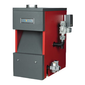
CROWN
Boiler Co
AWI & TWI Series
Gas-Fired Natural Draft Hot Water Boilers
INSTALLATION INSTRUCTIONS
These instructions must be affixed on or adjacent to the boiler
Tel: (215) 535-8900 • Fax: (215) 535-9736 • www.crownboiler.com
Models:
AWI037
•
AWI061
TWI061
•
•
AWI095
TWI095
•
•
AWI128
TWI128
•
•
AWI162
TWI162
•
•
AWI195
•
AWI229
•
AWI262
•
AWI295
•
CROWN
Boiler Co
Manufacturer of Hydronic Heatings Products
P.O. Box 14818 3633 I. Street
Philadelphia, PA 19134
1
WARNING: Improper installa-
tion, adjustment, alteration,
service or maintenance can
cause property damage, injury,
or loss of life. For assistance or
additional information, consult a
qualified installer, service
agency or the gas supplier.
Read these instructions carefully
before installing.
Advertisement
Table of Contents

Subscribe to Our Youtube Channel
Related Manuals for Crown Boiler AWI037


Summary of Contents for Crown Boiler AWI037
-
Page 1: Installation Instructions
Boiler Co AWI & TWI Series Gas-Fired Natural Draft Hot Water Boilers INSTALLATION INSTRUCTIONS These instructions must be affixed on or adjacent to the boiler CROWN Manufacturer of Hydronic Heatings Products Tel: (215) 535-8900 • Fax: (215) 535-9736 • www.crownboiler.com... - Page 2 INSIDE FRONT COVER (LEAVE BLANK)
-
Page 3: Table Of Contents
VII. Gas Piping ... 11 The AWI series boiler is a cast iron gas fired water boiler designed for use in closed forced circulation heating systems. This boiler is a Category I draft diverter equipped appliance, which must be vented by natural draft using a lined masonry or listed metal chimney system. - Page 4 FIGURE 1B: “LEFT PIPED” CONFIGURATION FIGURE 1C: “TOP PIPED” (T-AWI OR T-TWI) CONFIGURATION...
- Page 5 TABLE 1: SPECIFICATIONS Notes: Suffix E = Intermittent Ignition, Suffix S = Standing Pilot Add Suffix N for Natural Gas or Suffix L for Propane Gas to basic AWI Boiler Model shown (Example: AWI295EN, AWI229SL) A " " " " B C "...
-
Page 6: Iii Before Installing
2) The boiler must be installed on a hard level surface. This surface may be combustible. 3) Do not install this boiler in a location where gasoline or other flammable vapors or liquids will be stored or used. Do not install this boiler in an area where large amounts of airborne dust will be present, such as a workshop. -
Page 7: Air For Combustion & Ventilation
For Buildings of Other than Unusually Tight Construction 1) Determine whether the boiler is to be installed in a confined space - A confined space is defined by the National Fuel Gas Code as having a volume less than 50 cubic feet per 1000 BTU/hr input of all appliances installed in that space. To determine whether the boiler room is a confined space: Total the input of all appliances in the boiler room in thousands of BTU/hr. - Page 8 3) Confined Space - Provide two openings into the boiler room, one near the floor and one near the ceiling. The top edge of the upper opening must be within 12” of the ceiling and the bottom edge of the lower opening must be within 12” of the floor (Figure 3).
- Page 9 Openings to outdoors via horizontal ducts (Figure 7) - Each opening must have a free cross sectional area of 1 square inch per 2000 BTU/hr of the total input of all gas fired appliances in the boiler room but not less than 100 square inches.
-
Page 10: Venting
Typical vent installation is illustrated by Figure 8. The components of vent installation are boiler draft diverter, vent damper, vent connector and chimney. The AWI and TWI series boilers are equipped with a draft diverter which is built into the boiler;... - Page 11 An exterior masonry chimney may be used if it is lined with B vent or a listed chimney lining system. This boiler may vented using a listed power venter. The power venter must be in sized and installed in accordance with the power venter manufacturer’s instructions, the terms of the power venter listing, and applicable codes.
- Page 12 12) Vent pipe must be inserted flush with inside face of the chimney liner and the space between vent pipe and chimney sealed tight. 13) Do not install the vent damper in any portion of the vent system which is used by appliances other the boiler being installed.
-
Page 13: Vii Gas Piping
National Fuel Gas Code, ANSI Z223.1. Gas piping to the boiler must be sized to deliver adequate gas for the boiler to fire at the nameplate input at a line pressure between the minimum and maximum values shown on the rating plate. For more information on gas line sizing, consult the utility or Part 2 of the National Fuel Gas Code. -
Page 14: Viii System Piping
Berkeley Heights, NJ. The components in this system and their purposes are as follows: 1) Relief valve (Required) - Mount the relief valve on the right side of the boiler as shown in Figure 1 using the 3/4 nipples and elbow provided. The relief valve shipped with the boiler is set to open at 30 psi. This valve may be replaced with one having a pressure up to the “Maximum Allowable Working Pressure”... -
Page 15: Piping For Special Situations
9) Isolation Valves (Optional) - Isolation valves are useful if the boiler must be drained, as they will eliminate having to drain and refill the entire system. 10) Drain Valve - The drain valve is shipped in the boiler parts bag. Install it in the tee under the circulator as shown in Figure 1. - Page 16 • Systems which are open to the atmosphere. If the boiler is to be used in such a system, it must be separated from the oxygenated water being heated with a heat exchanger as shown in Figure 14. Consult the heat exchanger manufacturer for proper heat exchanger sizing as well as flow and temperature requirements.
- Page 17 5) Piping with a Chiller - If the boiler is used in conjunction with a chiller, pipe the boiler and chiller in parallel as shown in Figure 15. Use isolation valves to prevent chilled water from entering the boiler. 6) Air Handlers - Where the boiler is connected to air handlers through which refrigerated air passes, use flow control valves in the boiler piping or other automatic means to prevent gravity circulation during the cooling cycle.
-
Page 18: Wiring
National Electrical Code (ANSI/NFPA 70) 120 Volt Wiring - The boiler should be provided with its own 15A branch circuit with fused disconnect. All 120 volt connections are made inside the L8148E aquastat relay as follows (also see Fig. 16 or 17): •... - Page 19 FIGURE 16: WIRING DIAGRAM, CONTINUOUS IGNITION (STANDING PILOT) SYSTEM FIGURE 17: WIRING DIAGRAM, INTERMITTENT IGNITION (EI) SYSTEM...
- Page 20 The end switches are connected in parallel with each other and to the “T” and “TV” thermostat connections so that any zone valve that opens will also start the circulator and fire the boiler (assuming the high limit is not open). Zone valve terminal TH/TR has no internal connection on the zone valve;...
- Page 21 (“gas valve”) terminals “TH” and “TR”. 6) When the boiler is first placed into operation, the pilot must be lit. The pilot heats a thermocouple which generates a small amount of electricity sufficient to hold open the safety shut-off valve in the combination gas control. The circuit connecting the thermocouple and the safety shut-off valve is self contained and completely independent of all other wiring on the boiler.
- Page 22 Sequence of Operation, Intermittent Ignition 1) When the boiler is energized, 24 volts is immediately applied to terminals “1” (blue) and “4” (yellow) on the vent damper. Assuming that there is no call for heat, and that the damper switch is in the “automatic” position, the damper will close.
-
Page 23: Start-Up & Checkout
(see Figure 22 or 23). No yellow tipping should be present; however, intermittent flecks of yellow and orange in the flame are normal. 12) Check entire gas train for leaks using soap and water or other approved leak detection method while boiler is firing. Fix any leaks found immediately. - Page 24 Connect a manometer to the line pressure tap on the gas valve (see Figures 24 and 25). b) Check the line pressure with all gas appliances on and off. The line pressure at the boiler must be within the following limits regardless of what combination of appliances is firing: Line Press (inches w.c.)
- Page 25 20) After the boiler has operated for approximately 30 minutes, check the boiler and heating system piping for leaks. Repair any leaks found at once. 21) Inspect the vent system for flue gas leaks. Repair any leaks found before leaving the boiler in operation.
-
Page 26: For Your Safety Read Before Operating
FOR YOUR SAFETY READ BEFORE OPERATING WARNING: If you do not follow these instructions exactly, a fire or explosion may result causing property damage, personal injury or loss of life. A. This appliance has a pilot which must be lighted by hand. When lighting the pilot, follow these instructions exactly. -
Page 27: Operating Instructions
FOR YOUR SAFETY READ BEFORE LIGHTING WARNING: If you do not follow these instructions exactly, a fire or explosion may result causing property damage, personal injury or loss of life. A. This appliance is equipped with an ignition device which automatically lights the pilot. try to light the pilot by hand. - Page 28 FIGURE 24: GAS VALVE DETAIL - STANDING PILOT FIGURE 25: GAS VALVE DETAIL - INTERMITTENT IGNITION...
-
Page 29: Service & Maintenance
WATER LEAKS CAN CAUSE SEVERE CORROSION DAMAGE TO THE BOILER OR OTHER SYSTEM COMPO- NENTS. REPAIR ANY LEAKS FOUND IMMEDIATELY 12) Place the boiler back in operation using the procedure outlined in “Start-up”. Check the pilot line and any other gas piping disturbed during the inspection process for leaks. -
Page 30: Heat Exchanger Cleaning Procedure
Do not take a sample until the boiler has been firing for at least five minutes. -
Page 31: Xii Troubleshooting
5) These troubleshooting charts assume that the vent damper is closed at the beginning of the troubleshooting process. With the 120 volts applied to the boiler and no call for heat, the damper should go to the closed position. If it does not, do the following: •... - Page 32 C1 or C2 and circulator 24 volts across B and R (limit sw itch) in L8148E ? *Boiler off on limit *Defective high limit. 24 volts betw een pins 1&4 (blue&yellow )and 2&4 (orange&yellow ) on damper end of damper harness? See Note 7 on page 29.
- Page 33 Parts 7 and 11 of National Fuel Gas Code. *Dow n draft *Inadequate combustion air supply in boiler room *Rollout sw itch open. Replace w ith exact replacement (see parts list). Check for blocked heat exchanger.
- Page 34 Hold button for at least one minute. Does pilot light? Line pressure within the range indicated on boiler's rating plate? Consult gas supplier. *Pilot tubing blocked, kinked or leaking *Pilot orifice blocked *Gas line not...
- Page 35 Intermittent Ignition System Troubleshooting Chart START (24 volts is present across 5 and 6 on S8600 module, but main burners do not light) Spark across Pilot ignitor/sensor lights? gap? 24 volts across terminals 2&3 at S8600? Can you hear sparking? 24 volts across PV &...
-
Page 36: Xiii Parts
In some cases, the following parts lists do not include Crown part numbers because they were not available at the time of printing. Order these parts by their description, specifying the boiler model number on which they are to be used. - Page 37 Base-Block-Hood...
- Page 38 LOWER INJECTION SHIELD UPPER INJECTION SHIELD 1/4-20 BRASS WING NUT 10-32 x 3/16" SCREW * NOT PICTURED BELOW 2000 ft QTY. OR QUANTITY PER BOILER OR CROWN P.N. CROWN P.N. 150500 1 ea. 1 ea. 1 ea. 150501 1 ea.
- Page 39 1” BURNER COMPONENTS 50mm BURNER COMPONENTS...
- Page 40 DAMPER WIRE HARNESS AQUASTAT - R.O. SWITCH HARNESS SPILL SWITCH HARNESS INTERMITTENT IGNITION HARNESS GROUND WIRE HARNESS (EI ONLY) * NOT PICTURED QTY. OR QUANTITY PER BOILER OR CROWN P.N. CROWN P.N. 1 ea. 700301 700301 700301 1 ea. 700300...
- Page 41 Jacket/Components...
- Page 42 CROWN Boiler Co Manufacturer of Hydronic Heatings Products P.O. Box 14818 3633 I. Street Philadelphia, PA 19134 Tel: (215) 535-8900 • Fax: (215) 535-9736 • www.crownboiler.com...
Need help?
Do you have a question about the AWI037 and is the answer not in the manual?
Questions and answers