Table of Contents
Advertisement
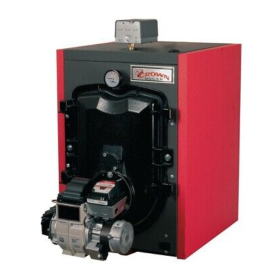
FWZ Series
Oil-Fired Hot Water Boilers
INSTALLATION INSTRUCTIONS
These instructions must be affixed on or adjacent to the boiler
Improper installation, adjustment, alteration, service or maintenance can cause property damage,
injury, or loss of life. For assistance or additional information, consult a qualified installer, service
agency or the gas supplier. This boiler requires a special venting system. Read these instructions
carefully before installing.
Models:
FWZ060
•
FWZ080
•
FWZ081
•
FWZ100
•
FWZ130
•
FWZ160
•
9802605 Rev A, 06-18
D
E S I G N E D
Equipped with Hydrolevel
3250-Plus Control System
L
T O
WARNING
E A D
Crown Boiler Company
P.O. Box 14818
3633 I Street
Philadelphia, PA 19134
www.crownboiler.com
Advertisement
Table of Contents

Related Manuals for Crown Boiler FWZ Series


Summary of Contents for Crown Boiler FWZ Series
- Page 1 E S I G N E D E A D FWZ Series Oil-Fired Hot Water Boilers INSTALLATION INSTRUCTIONS These instructions must be affixed on or adjacent to the boiler WARNING Improper installation, adjustment, alteration, service or maintenance can cause property damage, injury, or loss of life.
- Page 3 IMPORTANT INFORMATION - READ CAREFULLY All boilers must be installed in accordance with National, State and Local Plumbing, Heating and Electrical Codes and the regulations of the serving utilities. These Codes and Regulations may differ from this instruction manual. Authorities having jurisdiction should be consulted before installations are made.
- Page 4 DANGER DO NOT store or use gasoline or other flammable vapors or liquids in the vicinity of this or any other appliance. WARNING Improper installation, adjustment, alteration, service or maintenance can cause property damage, personal injury or loss of life. Failure to follow all instructions in the proper order can cause personal injury or death. Read and understand all instructions, including all those contained in component manufacturers manuals which are provided with the boiler before installing, starting-up, operating, maintaining or servicing this boiler.
- Page 5 WARNINGS FOR THE HOMEOWNER FOLLOW ALL INSTRUCTIONS and warnings printed or other safeguards are in place to prevent such in this manual and posted on the boiler. damage INSPECT THE BOILER, BURNER AND CONTROLS DO NOT BLOCK AIR FLOW into or around the boiler. ANNUALLY.
-
Page 6: Table Of Contents
WARNING This boiler must be properly vented. The chimney must be inspected for any obstructions and cleaned prior to each heating season. A clean and unobstructed chimney flue is necessary to produce the minimum draft required to safely evacuate noxious fumes that could cause personal injury or loss of life. Evidence of loose debris and or condensate induced stains at the base of the chimney flue, connector or smokepipe joints may be signs of condensing flue gases. -
Page 7: Product Description
I Product Description The FWZ series boiler is a cast iron oil-fired water boiler designed for use in closed forced circulation heating systems. This boiler must be vented by natural draft into a lined masonry or metal chimney, or Type L vent. An adequate supply of air for combustion, ventilation and dilution of flue gases must be available in the boiler room. -
Page 9: Before Installing
If a power venter must be used, it is the responsibility of the installer and power venter manufacturer to “engineer” the power vent system. CROWN BOILER COMPANY WILL ASSUME NO RESPONSIBILITY FOR DAMAGE TO SIDING, ETC. FROM A POWER VENTED OIL-... -
Page 10: Field Assembly
(Figure 4.0). Note that some burner boxes may contain rating plates for both water and steam models; be sure to select the appropriate FWZ series rating plate. Before applying the rating plate clean the... - Page 11 FIGURE 4.0: RATING PLATE LOCATION TABLE 4.1: BASIC BOILER CONFIGURATIONS Burner Burner 2nd Pass 2nd Pass 3rd Pass Boiler Model Burner Carton Blanket Tube Baffle Baffle Baffle Part No. Part # Insulation (410009) (410008) (410007) FWZ060 FWZ002 Beckett 41060B FWZ080 FWZ002 Beckett 41080B...
- Page 12 FIGURE 4.2: BAFFLE AND BLANKET INSTALLATION...
-
Page 13: Locating The Boiler
V Locating the Boiler WARNING Failure to observe the following location requirements could result in property damage, a fire, explosion or carbon monoxide (CO) hazard. 1) Clearances: • Observe the minimum clearances shown below. Except as noted, these clearances apply to all combustible construction, as well as noncombustible walls, ceilings and doors. -
Page 14: Air For Combustion & Ventilation
1) Do not install this boiler directly on a combustible floor. Where it is desired to install an FWZ on a non-carpeted combustible floor, install the boiler on a base constructed as shown in Figure 5.1 2) If listed Type L vent is used, follow vent pipe manufacturer recommendations for minimum clearances. 3) Do not install this boiler in a location where gasoline or other flammable vapors or liquids will be stored or used. - Page 15 A. For Buildings of Other than Unusually Tight Construction 1) Determine whether the boiler is to be installed in a confined space - A confined space is defined as having a volume less than 50 cubic feet per 1000 BTU/hr input of all appliances installed in that space. To determine whether the boiler room is a confined space: a) Total the input of all appliances in the boiler room in thousands of BTU/hr.
- Page 16 FIGURE 6.0: BOILER INSTALLED IN CONFINED SPACE, ALL AIR FROM INSIDE FIGURE 6.1: ALL AIR FROM OUTDOORS, VENTILATED CRAWL SPACE AND ATTIC...
- Page 17 FIGURE 6.2: ALL AIR FROM OUTDOORS, VIA VENTILATED ATTIC FIGURE 6.3: ALL AIR FROM OUTDOORS, USING OPENINGS INTO BOILER ROOM...
-
Page 18: Venting
FIGURE 6.4: ALL AIR FROM OUTDOORS, USING HORIZONTAL DUCTS INTO BOILER ROOM VII Venting WARNING • Improper venting may result in property damage and/or the release of flue gases, which contain deadly carbon monoxide (CO), into the home, which can cause severe personal injury or death. - Page 19 A typical vent system is illustrated in Figure 7.0. The components of the vent installation are the vent connector (breeching), barometric draft regulator, and chimney. 1) Acceptable Chimneys - The following chimneys may be used to vent a FWZ series boiler: •...
- Page 20 FIGURE 7.0: TYPICAL VENT SYSTEM INSTALLATION AND COMPONENTS TABLE 7.1: MINIMUM RECOMMENDED BREECHING AND CHIMNEY SIZE MINIMUM CHIMNEY REQUIREMENTS MINIMUM BOILER BREECHING MODEL ROUND I.D. SQUARE. TILE DIA. (INCHES) HEIGHT (FT.) (IN.) SIZE (NOMINAL) FWZ060 8 X 8 FWZ080 8 X 8 FWZ081 8 X 8 FWZ100...
-
Page 21: System Piping
VIII System Piping WARNING • Install boiler so that the electrical components are protected from water (dripping, spraying, rain, etc.) During appliance operation and service (circulator replacement, etc.). • Operation of this boiler with continuous return temperatures below 135°f can cause severe boiler or chimney damage. - Page 22 5) Fill Valve (Required) - Either a manual or automatic fill valve may be used. The ideal location for the fill is at the expansion tank. 6) Automatic Air Vent (Required) - At least one automatic air vent is required. Manual vents will usually be required in other parts of the system to remove air during initial fill.
- Page 23 FIGURE 8.1: INSTALLATION OF FACTORY SUPPLIED PIPING FIGURE 8.2: STANDARD BOILER PIPING...
- Page 24 B. Piping for Special Situations Certain types of heating systems have additional requirements. Some of the more common variations follow: 1) Indirect Water Heaters - Figure 8.3 shows typical indirect water heater piping. Boiler piping is the same as for any two zone system.
- Page 25 FIGURE 8.4: BYPASS PIPING FIGURE 8.5: ISOLATION OF BOILER FROM SYSTEM WITH A HEAT EXCHANGER...
-
Page 26: Fuel Line Piping
IX Fuel Line Piping WARNING • Under no circumstances can copper with sweat style connectors be used. • Do not use compression fittings. • Oil piping must be absolutely airtight or leaks or loss of prime may result. • Some jurisdictions require the use of a fusible shutoff valve at the tank and/or the burner. In addition, some jurisdictions require the use of a fusible electrical interlock with the burner circuit. - Page 27 7) Attach required piping between burner fuel pump and fuel oil storage tank. Install one fuel shut-off valve near the storage tank and second fuel shut-off valve near the oil burner fuel pump. Use a continuous run of copper tubing having a minimum wall thickness of 0.032”.
- Page 28 FIGURE 9.2: TWO-PIPE GRAVITY FEED SYSTEM (NOT RECOMMENDED) FIGURE 9.3: TWO-PIPE LIFT SYSTEM...
-
Page 29: Wiring
X Wiring WARNING • All wiring and grounding must be done in accordance with the authority having jurisdiction or, in the absence of such requirements, with the National Electrical Code (ANSI/NFPA 70). • Disconnect electrical power to the boiler and heating system before servicing. Positively assure that no voltage is present. - Page 30 NOTICE • When making low voltage connections, make sure that no external power source is present in the thermostat circuits. If such a power source is present, it could destroy the boiler’s control. One example of an external power source that could be inadvertently connected to the low voltage connections is a transformer in old thermostat wiring.
- Page 31 FIGURE 10.0: WIRING CONNECTIONS DIAGRAM FOR HYDROSTAT 3250-PLUS CONTROL...
- Page 32 FIGURE 10.1: CONNECTIONS WIRING DIAGRAM FOR BURNER SPECIFIC PRIMARY CONTROL...
-
Page 33: Start-Up & Checkout
XI Start-up and Checkout Use the following procedure for initial start-up of the boiler: WARNI NG • Never attempt to fill a hot empty boiler. • Make sure that the area around the boiler is clear and free from combustible materials, gasoline, and other flammable vapors and liquids. - Page 34 FIGURE 11.0: FLUE DRAFT TAPPING 18) After chimney has warmed-up for at least 5 minutes, adjust barometric draft regulator to obtain a draft at the 1/4” tapping shown in Figure 11.0 that is within the range shown in Table 11.1. DRAFT AT THIS LOCATION MUST NEVER BE POSITIVE.
- Page 35 WARNING Attempts to use burners or burner configurations other than those shown in Table 11.1 could result in reliability problems, property damage, personal injury or loss of life. TABLE 11.1a: BECKETT BURNER CONFIGURATION AND SETUP DATA BOILER MODEL FWZ060 FWZ080 FWZ081 FWZ100 FWZ130...
- Page 36 TABLE 11.1c: CARLIN BURNER CONFIGURATION AND SETUP DATA BOILER MODEL FWZ081 FWZ100 FWZ130 FWZ160 BURNER MODEL EZ1-LF EZ1-LF EZ1-LF EZ-66 BLENDER 28 HOLE NONE NONE NONE CARLIN AIR TUBE NUMBER 50989 50989 50989 51198 DANFOSS HAGO HAGO HAGO STANDARD NOZZLE 0.60 X 60AS 0.75 X 60B 1.00 X 45B...
-
Page 37: Operation
XII Operation A. General Information This boiler uses the Hydrolevel Hydrostat® model 3250-Plus control to provide control of boiler water temperature, as well as to manage demands for up to two circulator zones. In addition, this control also provides protection against low water conditions. This boiler complies with the 2007 Energy and Independence Security Act, using an “Economy”... - Page 38 B. Setting the Control NOTE: Settings can be checked using the TEST/SETTINGS button located on the top right of the control. See page 33 for details. 1) Setting the High Limit - The high limit is factory set at 190°F. To adjust, turn the HI TEMP dial A until the desired setting is displayed.
- Page 39 NOTE: DHW Priority: During a call from an indirect water heater, the control will de-energize the circulator contacts (C1/C2) to heat only the indirect tank ensuring an adequate supply of domestic hot water. The control will re-energize the circulator when the indirect tank is satisfied or if the boiler temperature reaches 170°F. If the indirect call continues for 45 minutes, the control will override the priority function energizing the circulator to provide space heating.
- Page 40 5) Circulator Hold Off (Enhanced Condensing Protection) - To reduce the potential for condensing, on a call for heat the control will allow the boiler to heat to 125°F prior to energizing the circulator. Once energized, the circulator will remain on for the duration of the heating call unless the boiler temperature drops below 115°F.
- Page 41 TABLE 12.2 DEFAULT SETTINGS Dial Default Feature Options Description Setting Setting Purge Inactive Thermal Pre-Purge Purge Active Degrees Fahrenheit Fahrenheit or Celsius Degrees Celsius LWCO Manual or Auto- Automatic Reset matic Reset Manual Reset Circulator operation on TT call only Circulator Options Circulator operation on ZC/ZR call only Circulator operation on call from either...
- Page 42 FIGURE 12.3 LED Legend and TEST/SETTINGS Button 5) ECONOMY - ACTIVE - Indicates that the thermal targeting function is active and the control will reduce boiler temperature to conserve fuel. The Economy feature is activated using the ECONOMY dial. (See “Setting the Economy Feature” on page 29 for more information).
-
Page 43: Service & Maintenance
XIII Service and Maintenance WARNING All boiler cleaning must be completed with the burner service switch turned off. Boilers equipped with burner swing door have a potential hazard which can cause severe property damage, personal injury or loss of life if ignored. Before opening swing door, turn off service switch to boiler to prevent accidental firing of burner outside the combustion chamber. - Page 44 WARNING The boiler must be connected to an approved chimney in good condition. Serious property damage could result if the boiler is connected to a dirty or inadequate chimney. The interior of the chimney flue must be inspected and cleaned before the start of the heating season and should be inspected periodically throughout the heating season for any obstructions.
- Page 45 Important Product Safety Information Refractory Ceramic Fiber Product Warning: The Parts list designates parts that contain refractory ceramic fibers (RCF). RFC has been classified as a possible human carcinogen. When exposed to temperatures about 1805°F, such as during direct flame contact, RFC changes into crystalline silica, a known carcinogen.
-
Page 46: Troubleshooting
XIV Trouble Shooting A. Combustion 1) Nozzles - The selection of the nozzle supplied with the FWZ boiler is the result of extensive testing to obtain the best flame shape and efficient combustion. Other brands of the same spray angle and pattern may be used but may not perform at the expected level of CO2 and smoke. - Page 47 B. Control System The following pages contain a trouble shooting table and flow charts for use in diagnosing control problems. When using these materials the following should be kept in mind: 1) This information is only meant to be used by a professional heating technician as an aid in diagnosing boiler problems. 2) Where applicable, follow all precautions outlined in the Section XI (Start-up and Checkout).
- Page 48 TABLE 14.0 - DIAGNOSTIC CONDITIONS Condition Possible Cause Burner will not fire See Flow Chart 1, page 46 Burner will not shut down See Flow Chart 2, page 47 Under normal operation, boiler temperature will continue to rise after the control shuts off Temperature display exceeds the burner.
- Page 49 Troubleshooting Flow Chart 1 – Burner Will Not Fire The Control is The Thermal Pre-Purge feature holds off the burner until the Does the Purging Latent control determines if the latent heat in the boiler can satisfy Display Read Heat from the the heat call.
- Page 50 Troubleshooting Flow Chart 2 – Burner Will Not Shut Down Is the The Control is Red LED Sensing (LOW WATER) Low Water. WARNING! TURN OFF POWER TO BURNER IMMEDIATELY! CAUTION – ALWAYS ALLOW A BOILER TO FULLY COOL BEFORE ADDING WATER. Recheck wiring.
-
Page 51: Parts
XV Parts QTY. OR QUANTITY PER BOILER OR CROWN PART NUMBER KEY # DESCRIPTION CROWN FWZ060 FWZ080 FWZ081 FWZ100 FWZ130 FWZ160 HEAT EXCHANGER ASSEMBLY 410012 410012 410013 410013 410014 410015 SPANNER BAR 410402 410402 410403 410403 410404 410405 NYLON GLIDE 700111 HEX HD CAP SCREW 5/16-18 X 7/8”... - Page 53 QTY. OR QUANTITY PER BOILER OR CROWN PART NUMBER KEY # DESCRIPTION CROWN FWZ060 FWZ080 FWZ081 FWZ100 FWZ130 FWZ160 FRONT JACKET PANEL 410310 RIGHT SIDE JACKET PANEL 410302 410302 410303 410303 410304 410305 LEFT SIDE JACKET PANEL 410312 410312 410313 410313 410314 410315...
- Page 54 QUANTITY PER BOILER OR CROWN PART NUMBER QTY. OR KEY # DESCRIPTION CROWN PN FWZ060 FWZ080 FWZ081 FWZ100 FWZ130 FWZ160 BECKETT OIL BURNER ASSY 41060B 41080B 41081B 41100B 41130B 41160B RIELLO OIL BURNER ASSY 41060R 41081R 41100R 41130R 41160R CARLIN OIL BURNER ASSY 41081C 41100C 41130C...
- Page 56 Manufacturer of Hydronic Heating Products P.O. Box 14818 3633 I. Street Philadelphia, PA 19134 www.crownboiler.com...
Need help?
Do you have a question about the FWZ Series and is the answer not in the manual?
Questions and answers