Table of Contents
Advertisement
Quick Links
Advertisement
Table of Contents

Related Manuals for Supero 2U Twin3 SuperServer 2015TA-HTRF


Summary of Contents for Supero 2U Twin3 SuperServer 2015TA-HTRF
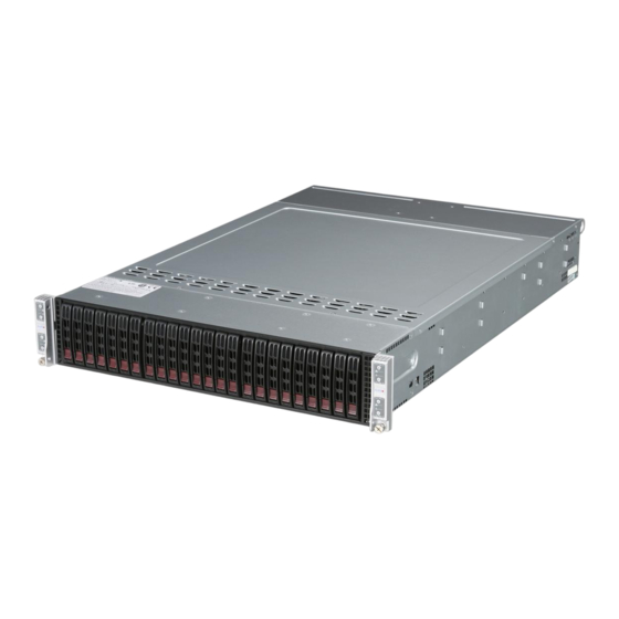
- Page 1 ® UPER 2U Twin SuperServer 2015TA-HTRF USER’S MANUAL Revision 1.0...
- Page 2 The information in this User’s Manual has been carefully reviewed and is believed to be accurate. The vendor assumes no responsibility for any inaccuracies that may be contained in this document, makes no commitment to update or to keep current the information in this manual, or to notify any person or organization of the updates.
-
Page 3: About This Manual
Preface Preface About This Manual This manual is written for professional system integrators and PC technicians. It provides information for the installation and use of the SuperServer 2015TA-HTRF. Installation and maintenance should be performed by experienced technicians only. The SuperServer 2015TA-HTRF is a 2U Twin (eight serverboards/nodes in a 2U chassis) rackmount server based on the SC217HO-R720B server chassis and eight Super X7SPT-DF-D525 serverboards. - Page 4 SUPERSERVER 2015TA-HTRF User's Manual to this chapter when adding or removing processors or main memory and when reconfi guring the serverboard. Chapter 6: Advanced Chassis Setup Refer to Chapter 6 for detailed information on the SC217HO-R720B 2U rackmount server chassis. You should follow the procedures given in this chapter when install- ing, removing or reconfi...
- Page 5 Preface Notes...
-
Page 6: Table Of Contents
SUPERSERVER 2015TA-HTRF User's Manual Table of Contents Chapter 1 Introduction Overview ......................1-1 Motherboard Features ..................1-2 Processor ......................1-2 Memory ......................1-2 Onboard SATA ....................1-2 Onboard Controllers/Ports ................1-2 Other Features ....................1-2 Onboard Graphics ................... 1-2 Server Chassis Features ................1-4 System Power .................... - Page 7 Table of Contents Installing The Inner Rails on the Chassis ............2-6 Installing the Outer Rails on the Rack ............2-7 Standard Chassis Installation ................. 2-8 Checking the Serverboard Setup ..............2-9 Preparing to Power On ................. 2-10 Chapter 3 System Interface Overview ......................
- Page 8 SUPERSERVER 2015TA-HTRF User's Manual 5-13 Installing Software ..................5-17 Supero Doctor III ................... 5-18 Chapter 6 Advanced Chassis Setup Static-Sensitive Devices .................. 6-1 Precautions ..................... 6-1 Unpacking ....................... 6-1 Control Panel ....................6-2 System Fans ....................6-2 Fan Confi guration .................... 6-3 System Fan Failure ..................
-
Page 9: Chapter 1 Introduction
Chapter 1: Introduction Chapter 1 Introduction Overview The Supermicro SuperServer 2015TA-HTRF is a 2U Twin rackmount server. The 2015TA-HTRF is comprised of two main subsystems: the SC217HO-R720B chassis and eight X7SPT-DF-D525 motherboards. Please refer to our web site for informa- tion on operating systems that have been certifi... -
Page 10: Motherboard Features
UPER ERVER 2015TA-HTRF User's Manual Motherboard Features At the heart of the SuperServer 2015TA-HTRF are eight X7SPT-DF-D525 moth- erboards, which are single processor, low-power motherboards based upon Intel's ATOM D525 + ICH9R chipset. Below are the main features of the X7SPT-DF- D525. - Page 11 Chapter 1: Introduction Factory Option FROM BMC 12V DC PSU DDR3-800 Connector 4-PIN CONN Intel ATOM D525 ATX PSU 24PIN CONN SATA Port 4 SATA Port 3 SATA GEN2 SATA Port 5 SATA Port 2 PCI-E x16 SATA Port 6 SATA Port 1 PCI-E x4 Slot...
-
Page 12: Server Chassis Features
UPER ERVER 2015TA-HTRF User's Manual Server Chassis Features The following is a general outline of the main features of the SC217HO-R720B 2U chassis. Details on the chassis can be found in Chapter 6. System Power The SC217HO-R720B includes a redundant (dual) 720W power supply, which provides power to both serverboards (nodes). -
Page 13: Twin 3 : System Notes
Chapter 1: Introduction 2U Twin : System Notes As a 2U Twin confi guration, the 2015TA-HTRF is a unique server system. With eight system boards incorporated into a single chassis acting as eight separate nodes, there are several points you should keep in mind. Nodes Each of the serverboards act as a separate node in the system. -
Page 14: Contacting Supermicro
UPER ERVER 2015TA-HTRF User's Manual Contacting Supermicro Headquarters Address: Super Micro Computer, Inc. 980 Rock Ave. San Jose, CA 95131 U.S.A. Tel: +1 (408) 503-8000 Fax: +1 (408) 503-8008 Email: marketing@supermicro.com (General Information) support@supermicro.com (Technical Support) Web Site: www.supermicro.com Europe Address: Super Micro Computer B.V. -
Page 15: Chapter 2 Server Installation
Chapter 2: Server Installation Chapter 2 Server Installation Overview This chapter provides a quick setup checklist to get the 2015TA-HTRF up and running. Following these steps in the order given should enable you to have the system operational within a minimum amount of time. This quick setup assumes that your system has come to you with the processors and memory preinstalled. -
Page 16: Choosing A Setup Location
SUPERSERVER 2015TA-HTRF User's Manual Choosing a Setup Location • Leave enough clearance in front of the rack to enable you to open the front door completely (~25 inches). • Leave approximately 30 inches of clearance in the back of the rack to allow for suffi... -
Page 17: Rack Mounting Considerations
Chapter 2: Server Installation • Allow the hot plug hard drives and power supply modules to cool before touch- ing them. • Always keep the rack's front door and all panels and components on the servers closed when not servicing to maintain proper cooling. •... -
Page 18: Removing The Protective Film
SUPERSERVER 2015TA-HTRF User's Manual Removing the Protective Film Before operating the server for the fi rst time, it is important to remove the protec- tive fi lm covering the top of the chassis, in order to allow for proper ventilation and cooling. -
Page 19: Rack Mounting Instructions
Chapter 2: Server Installation Rack Mounting Instructions This section provides information on installing the SC217 chassis into a rack unit with the quick-release rails provided. There are a variety of rack units on the market, which may mean the assembly procedure will differ slightly. You should also refer to the installation instructions that came with the rack unit you are using. -
Page 20: Installing The Inner Rails On The Chassis
SUPERSERVER 2015TA-HTRF User's Manual Inner Rails Figure 2-3: Installing the Inner Rails Installing The Inner Rails on the Chassis Installing the Inner Rails Confi rm that the left and right inner rails have been correctly identifi ed. Place the inner rail fi rmly against the side of the chassis, aligning the hooks on the side of the chassis with the holes in the inner rail. -
Page 21: Installing The Outer Rails On The Rack
Chapter 2: Server Installation Figure 6-5: Extending and Releasing the Outer Rails Installing the Outer Rails on the Rack Installing the Outer Rails Press upward on the locking tab at the rear end of the middle rail. Push the middle rail back into the outer rail. Hang the hooks of the front of the outer rail onto the slots on the front of the rack. -
Page 22: Standard Chassis Installation
SUPERSERVER 2015TA-HTRF User's Manual Figure 6-6: Installing into a Rack Standard Chassis Installation Installing the Chassis into a Rack Confi rm that the inner rails are properly installed on the chassis. Confi rm that the outer rails are correctly installed on the rack. Pull the middle rail out from the front of the outer rail and make sure that the ball-bearing shuttle is at the front locking position of the middle rail. -
Page 23: Checking The Serverboard Setup
Chapter 2: Server Installation Depress the locking tabs of both sides at the same time and push the chassis all the way into the rear of the rack. If necessary for security purposes, use screws to secure the chassis handles to the front of the rack. -
Page 24: Preparing To Power On
SUPERSERVER 2015TA-HTRF User's Manual Preparing to Power On Next, you should check to make sure the hard drives and the backplane have been properly installed and all connections have been made. Checking the Hard Drives The hard disk drives are accessable from the front of the server and can be installed and removed from the front of the chassis without removing the top chassis cover. - Page 25 Chapter 2: Server Installation Figure 2-6. Removing a Node from the System 2-11...
- Page 26 SUPERSERVER 2015TA-HTRF User's Manual Notes 2-12...
-
Page 27: Chapter 3 System Interface
Chapter 3: System Interface Chapter 3 System Interface Overview There are LEDs on the control panels and on the hard drive carriers to keep you constantly informed of the overall status of the system as well as the activity and health of specifi... -
Page 28: Control Panel Leds
SUPERSERVER 2015TA-HTRF User's Manual Control Panel LEDs In addition to the LEDs built into the power buttons, each of the four control panels located on the front of the SC217 chassis has two LEDs that provide you with critical information related their own node. This section explains what each LED indicates when illuminated and any corrective action you may need to take. -
Page 29: Drive Carrier Leds
Chapter 3: System Interface Drive Carrier LEDs Each drive carrier has two LEDs. • Blue: When illuminated, this blue LED (on the front of the drive carrier) indicates drive activity. A connection to the backplane enables this LED to blink on and off when that particular drive is being accessed. - Page 30 SUPERSERVER 2015TA-HTRF User's Manual Notes...
-
Page 31: Chapter 4 System Safety
Chapter 4: System Safety Chapter 4 System Safety Electrical Safety Precautions Basic electrical safety precautions should be followed to protect yourself from harm and the SuperServer 2015TA-HTRF from damage: • Be aware of the locations of the power on/off switch on the chassis as well as the room's emergency power-off switch, disconnection switch or electrical outlet. -
Page 32: General Safety Precautions
SUPERSERVER 2015TA-HTRF User's Manual • This product may be connected to an IT power system. In all cases, make sure that the unit is also reliably connected to Earth (ground). • Serverboard Battery: CAUTION - There is a danger of explosion if the onboard battery is installed upside down, which will reverse its polarites (see Figure 4-1). -
Page 33: Esd Precautions
Chapter 4: System Safety • Remove any jewelry or metal objects from your body, which are excellent metal conductors that can create short circuits and harm you if they come into contact with printed circuit boards or areas where power is present. •... -
Page 34: Operating Precautions
SUPERSERVER 2015TA-HTRF User's Manual Operating Precautions Care must be taken to assure that the chassis cover is in place when the 2015TA- HTRF is operating to assure proper cooling. Out of warranty damage to the system can occur if this practice is not strictly followed. Please handle used batteries carefully. -
Page 35: Chapter 5 Advanced Motherboard Setup
Chapter 5: Advanced Motherboard Setup Chapter 5 Advanced Motherboard Setup This chapter covers the steps required to install the X7SPT-DF-D525 motherboard into the chassis, connect the data and power cables and install add-on cards. All motherboard jumpers and connections are also described. A layout and quick refer- ence chart are included in this chapter for your reference. -
Page 36: Unpacking
UPER ERVER 2015TA-HTRF User's Manual Unpacking The motherboard is shipped in antistatic packaging to avoid electrical static dis- charge. When unpacking the board, make sure the person handling it is static protected. Motherboard Installation This section explains the fi rst step of physically mounting the X7SPT-DF-D525 into the SC217HO-R720B. -
Page 37: Connecting Cables
Chapter 5: Advanced Motherboard Setup Connecting Cables Now that the motherboard is installed, the next step is to connect the cables to the board. These include the data cables for the peripherals and control panel and the power cables. Connecting Data Cables The cables used to transfer data from the peripheral devices have been carefully routed to prevent them from blocking the fl... -
Page 38: I/O Ports
UPER ERVER 2015TA-HTRF User's Manual Figure 5-1. Control Panel Header Pins Ground Power LED HDD LED NIC1 LED NIC2 LED OH/Fan Fail LED Power Fail LED Reset Reset Button Ground Power Button Ground I/O Ports The I/O ports are color coded in conformance with the PC 99 specifi cation. See Figure 5-2 below for the colors and locations of the various I/O ports. -
Page 39: Onboard Processor
Chapter 5: Advanced Motherboard Setup Onboard Processor The Intel Atom processor is soldered directly onto the motherboard. Installing and removing the processor is not required. A small active heatsink sits on the proces- sor to keep it cool. Installing Memory Note: Check the Supermicro web site for recommended memory modules. - Page 40 UPER ERVER 2015TA-HTRF User's Manual Figure 5-3. DIMM Installation Position the SO-DIMM mod- Align ule's bottom key so that it aligns with the receptive point on the slot. Insert the SO-DIMM module vertically at about a 45 degree angle. Press down until the module locks into place.
-
Page 41: Motherboard Details
Chapter 5: Advanced Motherboard Setup Motherboard Details Figure 5-4. X7SPT-DF-D525 Layout JKPL2 Node 2 JCOM2 JKDIMM2 JKDIMM1 JCOM1 JKCOM2 JKPB BKT1 LKE1 JDIMM1 JDIMM2 Node 1 JSMB1... - Page 42 UPER ERVER 2015TA-HTRF User's Manual Number Connector Description JKVGA1, JVGA1 Video/Graphics Connector JKLAN1/JKLAN2, RJ45 Connector for LAN1 and LAN2 JLAN1/JLAN2 5,10 JK666, J666 (top) IPMI Dedicated LAN 13, 22 JCOM2,JKCOM2 Internal Serial Port (COM2) 14, 23 JCOM1,JKCOM1 Internal Serial Port (COM1) 17, 36 SKP1, SP1 Onboard Speaker...
-
Page 43: Connector Defi Nitions
Chapter 5: Advanced Motherboard Setup Connector Defi nitions Serial Ports COM1/COM2 Pin Defi nitions Serial Ports (OEM Option) Pin # Defi nition Pin # Defi nition Two onboard serial port headers (COM1, COM2) are located on the motherboard for each node. See the table on the right for pin defi... - Page 44 UPER ERVER 2015TA-HTRF User's Manual Trusted Platform Module Header Pin Defi nitions TPM Header (JTPM/JKTPM) Pin # Defi nition Pin # Defi nition This header is used to connect a Trusted LCLK Platform Module (TPM) from a third-party LFRAME No Pin vendor.
- Page 45 Chapter 5: Advanced Motherboard Setup LAN Ports LAN Port For each node: There are LAN ports Pin Defi nitions located on the I/O back panel. These Pin # Defi nition Pin # Defi nition ports accept RJ45 type cables. There TX_D1+ BI_D3- are two Ethernet ports (LAN1 &...
-
Page 46: Jumper Settings
UPER ERVER 2015TA-HTRF User's Manual Jumper Settings Explanation of Jumpers To modify the operation of the mother- board, jumpers can be used to choose Connector between optional settings. Jumpers Pins create shorts between two pins to change the function of the connector. Pin 1 is identifi... - Page 47 Chapter 5: Advanced Motherboard Setup SMB (I C) Bus to PCI Slots C to PCI-Slots Jumpers JI C1 and JI C2 allow you Jumper Settings to connect the System Management Jumper Defi nition Bus (SMB) to the PCI-E PCI slot. The Enabled default setting is Disabled.
-
Page 48: 5-10 Onboard Indicators
UPER ERVER 2015TA-HTRF User's Manual 5-10 Onboard Indicators LAN1/2 LEDs LAN1/2 LED A total of four LAN (Ethernet) ports are (Connection Speed Indicator) located on the I/O back panel. Each LED Color Defi nition have two LEDs. The yellow LED indi- No Connection or 10 Mb/s cates activity while the other LED may Green... -
Page 49: 5-11 Sata Ports
Chapter 5: Advanced Motherboard Setup 5-11 SATA Ports SATA Ports SATA Port Four Serial ATA (SATA) ports are sup- Pin Defi nitions ported on each node. IKSATA/ISATA1 Pin# Defi nition Pin # Defi nition are located on the motherboard while Ground the rest are supported through the Ground... -
Page 50: 5-12 Node Hot-Swapping
UPER ERVER 2015TA-HTRF User's Manual 5-12 Node Hot-Swapping The X7SPT-DF-D525 supports cable-free node hot-swapping when installed in a Supermicro 2U Twin server chassis together with the cable-free hot-swap adapter (both sold separately). Node hot-swapping enables the user to replace a mother- board in a multi-node server without powering down the entire system. -
Page 51: 5-13 Installing Software
Chapter 5: Advanced Motherboard Setup 5-13 Installing Software After the hardware has been installed, you should fi rst install the operating system and then the drivers. The necessary drivers are all included on the Supermicro CDs that came packaged with your motherboard. Driver/Tool Installation Display Screen (example shown) Note: Click the icons showing a hand writing on paper to view the readme fi... -
Page 52: Supero Doctor Iii
The Supero Doctor III program is a web-based management tool that supports remote management capability. It includes Remote and Local Management tools. The local management is called SD III Client. The Supero Doctor III program in- cluded on the CD-ROM that came with your motherboard allows you to monitor the environment and operations of your system. - Page 53 Chapter 5: Advanced Motherboard Setup Supero Doctor III Interface Display Screen (Remote Control) Note: SD III Software Revision 1.0 can be downloaded from our Web Site at: ftp://ftp. supermicro.com/utility/Supero_Doctor_III/. You can also download the SDIII User's Guide at: <http://www.supermicro.com/manuals/other/SDIII_User_Guide.pdf>. For Linux, we will recommend using Supero Doctor II.
- Page 54 UPER ERVER 2015TA-HTRF User's Manual Notes 5-20...
-
Page 55: Chapter 6 Advanced Chassis Setup
Chapter 6: Advanced Chassis Setup Chapter 6 Advanced Chassis Setup This chapter covers the steps required to install components and perform mainte- nance on the SC217HO-R720B chassis. For component installation, follow the steps in the order given to eliminate the most common problems encountered. If some steps are unnecessary, skip ahead to the step that follows. -
Page 56: Control Panel
SUPERSERVER 2015TA-HTRF User's Manual Figure 6-1. Chassis Front View Node B Control Panel Node D Control Panel SATA Drives Node A Control Panel Node C Control Panel Figure 6-2. Chassis Rear View Power Supplies LAN Ports USB Ports VGA Port Control Panel Each control panel on the front of the chassis must be connected to the JF2 con- nector on its associated serverboard to provide you with system control buttons... -
Page 57: Fan Confi Guration
Chapter 6: Advanced Chassis Setup Fan Confi guration In the 2U Twin , each node (serverboard) controls the fans that reside on its side of the chassis. This means that four nodes will share control for two fans. If the fan speed settings in BIOS are different for these two nodes, the BIOS setting with the higher fan speed will apply. -
Page 58: Hard Drive Installation/Removal
SUPERSERVER 2015TA-HTRF User's Manual Hard Drive Installation/Removal Overview The hard drives are mounted in drive carriers to simplify their installation and removal from the chassis. These carriers also help promote proper airfl ow for the system. For this reason, even empty carriers without drives installed must remain in the chassis. - Page 59 Chapter 6: Advanced Chassis Setup Figure 6-3. Mounting a Hard Drive in a Carrier Installing/Removing Hot-swap Drives To remove a carrier, push the release button located beside the drive LEDs. Swing the handle fully out and use it to pull the unit straight out (see Figure 6-4).
- Page 60 SUPERSERVER 2015TA-HTRF User's Manual Figure 6-4. Removing a Hard Drive Figure 6-5. Drives and Nodes: Logical Confi guration Note: see Figure 6-1 for the locations of the control panels that are associated with each node.
-
Page 61: Node Installation/Removal
Chapter 6: Advanced Chassis Setup Node Installation/Removal As with any server system, power must be removed from the serverboard when upgrading or installing memory or processors. In the 2U Twin server, the server- boards (nodes) are capable of being hot-swapped from the chassis, allowing some to be powered down for servicing while the others continue operating. - Page 62 SUPERSERVER 2015TA-HTRF User's Manual Figure 6-6. Removing a System Node Note: numbers correspond to the procedural steps as described on the previous page.
-
Page 63: Power Supply
Chapter 6: Advanced Chassis Setup Power Supply The SuperServer 2015TA-HTRF server has two 720 watt power supply modules to provide redundant power for the system. If either of the two power supply modules fail, the other module will take the full load and allow the system to continue opera- tion without interruption. - Page 64 SUPERSERVER 2015TA-HTRF User's Manual Figure 6-7. Removing the Power Supply Release Tab 6-10...
-
Page 65: Chapter 7 Bios
Chapter 7: BIOS Chapter 7 BIOS Introduction This chapter describes the AMI BIOS Setup Utility for the X7SPT-DF-D525. The AMI ROM BIOS is stored in a Flash EEPROM and can be easily updated. This chapter describes the basic navigation of the AMI BIOS Setup Utility setup screens. Note: For instructions on BIOS recovery, please refer to the instruction guide posted at http://www.supermicro.com/support/manuals/. -
Page 66: Main Setup
SUPERSERVER 2015TA-HTRF User's Manual How to Start the Setup Utility Normally, the only visible Power-On Self-Test (POST) routine is the memory test. As the memory is being tested, press the <Delete> key to enter the main menu of the AMI BIOS Setup Utility. From the main menu, you can access the other setup screens. - Page 67 Chapter 7: BIOS System Overview: The following BIOS information will be displayed: System Time/System Date Use this option to change the system time and date. Highlight System Time or Sys- tem Date using the arrow keys. Enter new values through the keyboard. Press the <Tab>...
-
Page 68: Advanced Setup Confi Gurations
SUPERSERVER 2015TA-HTRF User's Manual Advanced Setup Confi gurations Use the arrow keys to select Boot Setup and hit <Enter> to access the submenu items: BOOT Feature Quick Boot If Enabled, this option will skip certain tests during POST to reduce the time needed for system boot. - Page 69 Chapter 7: BIOS Bootup Num-Lock This feature selects the Power-on state for Numlock key. The options are Off and On. Wait For 'F1' If Error This forces the system to wait until the 'F1' key is pressed if an error occurs. The options are Disabled and Enabled.
-
Page 70: Advanced Chipset Control
SUPERSERVER 2015TA-HTRF User's Manual CPU Confi guration Warning : Take Caution when changing the Advanced settings. An incorrect value, a very high DRAM frequency or incorrect DRAM timing may cause system to become unstable. When this occurs, revert to the default setting. Clock Spread Spectrum Select Enable to use the feature of Clock Spectrum, which will allow the BIOS to monitor and attempt to reduce the level of Electromagnetic Interference caused by... - Page 71 Chapter 7: BIOS DRAM CAS# Latency The options are [3], [4], [5], and [6] DRAM RAS# to CAS# Delay The options are 3 DRAM Clocks, 4 DRAM Clocks, 5 DRAM Clocks, and 6 DRAM Clocks. DRAM RAS# Precharge The options are 3 DRAM Clocks, 4 DRAM Clocks, 5 DRAM Clocks, and 6 DRAM Clocks.
- Page 72 SUPERSERVER 2015TA-HTRF User's Manual IDE/SATA Confi guration When this submenu is selected, the AMI BIOS automatically detects the presence of the IDE Devices and displays the following items: SATA#1 Confi guration If Compatible is selected, it sets SATA#1 to legacy compatibility mode, while se- lecting Enhanced sets SATA#1 to native SATA mode.
- Page 73 Chapter 7: BIOS Block (Multi-Sector Transfer) Block Mode boosts the IDE drive performance by increasing the amount of data transferred. Only 512 bytes of data can be transferred per interrupt if Block Mode is not used. Block Mode allows transfers of up to 64 KB per interrupt. Select Disabled to allow data to be transferred from and to the device one sector at a time.
- Page 74 SUPERSERVER 2015TA-HTRF User's Manual Select MWDMA2 to allow the BIOS to use Multi-Word DMA mode 2. It has a data transfer rate of 16.6 MBs. Select UDMA0 to allow the BIOS to use Ultra DMA mode 0. It has a data transfer rate of 16.6 MBs.
- Page 75 Chapter 7: BIOS PCI Latency Timer This feature sets the latency Timer of each PCI device installed on a PCI bus. Select 64 to set the PCI latency to 64 PCI clock cycles. The options are 32, 64, 96, 128, 160, 192, 224 and 248.
- Page 76 SUPERSERVER 2015TA-HTRF User's Manual If Remote Access is set to Enabled, the following items will display: Serial Port Number This feature allows the user decide which serial port to be used for Console Redirection. The options are COM 1, COM 2 and COM 3. Serial Port Mode This feature allows the user to set the serial port mode for Console Redirection.
- Page 77 Chapter 7: BIOS Warning: Any temperature that exceeds the CPU threshold temperature predefi ned by the CPU manufacturer may result in CPU overheat or system instability. When the CPU temperature reaches this predefi ned threshold, the CPU and system cooling fans will run at full speed. The options are: •...
- Page 78 SUPERSERVER 2015TA-HTRF User's Manual even with the CPU fan running at full speed, the system buzzer will activate and the Overheat LED will turn on. The Early Alarm – the Overheat LED and system buzzer will be activated exactly when the High level is reached. The CPU fan will run at full speed to bring the CPU temperature down.
- Page 79 Chapter 7: BIOS system cooling. The Performance setting is recommended for high-power-consum- ing and high-density systems. Select Balanced for the onboard fans to run at 50% of the Initial PWM Cycle in order to balance the needs between system cooling and power saving.
- Page 80 SUPERSERVER 2015TA-HTRF User's Manual ACPI APIC Support Select Enabled to include the ACPI APIC Table Pointer in the RSDT (Root System Description Table) pointer list. The options are Enabled and Disabled. APIC ACPI SCI IRQ When this item is set to Enabled, APIC ACPI SCI IRQ is supported by the system. The options are Enabled and Disabled.
- Page 81 Chapter 7: BIOS Clear BMC System Event Log This feature is used to clear the System Event Log. Caution: Any cleared information is unrecoverable. Make absolutely sure you no longer need any data stored in the log before clearing the BMC Event Log. Set LAN Confi...
- Page 82 SUPERSERVER 2015TA-HTRF User's Manual BMC Watch Dog Timer Action Allows the BMC to reset or power down the system if the operating system hangs or crashes. The options are Disabled, Reset System, Power Down, Power Cycle. BMC WatchDog TimeOut [Min:Sec] This option appears if BMC Watch Dog Timer Action (above) is enabled.
-
Page 83: Security Settings
Chapter 7: BIOS Security Settings The AMI BIOS provides a Supervisor and a User password. If you use both pass- words, the Supervisor password must be set fi rst. Supervisor Password This item indicates if a supervisor password has been entered for the system. Clear means such a password has not been used and Set means a supervisor password has been entered for the system. - Page 84 SUPERSERVER 2015TA-HTRF User's Manual Change User Password Select this feature and press <Enter> to access the submenu , and then type in a new User Password. Clear User Password (Available only if User Password has been set) Password Check Available options are Setup and Always. Boot Sector Virus Protection When Enabled, the AMI BOIS displays a warning when any program (or virus) is- sues a Disk Format command or attempts to write to the boot sector of the hard...
-
Page 85: Boot Settings
Chapter 7: BIOS Boot Settings Use this feature to confi gure Boot Settings: Boot Device Priority This feature allows the user to specify the sequence of priority for the Boot Device. The settings are 1st boot device, 2nd boot device, 3rd boot device, 4th boot device, 5th boot device and Disabled. -
Page 86: Exit Options
SUPERSERVER 2015TA-HTRF User's Manual Removable Drives This feature allows the user to specify the boot sequence from available Removable Drives. The settings are 1st boot device, 2nd boot device, and Disabled. • 1st Drive • 2nd Drive - [USB: XXXXXXXXX] Retry Boot Devices Select this option to retry booting from the confi... - Page 87 Chapter 7: BIOS fi guration parameters can take effect. Select Save Changes and Exit from the Exit menu and press <Enter>. Discard Changes and Exit Select this option to quit the BIOS Setup without making any permanent changes to the system confi guration, and reboot the computer. Select Discard Changes and Exit from the Exit menu and press <Enter>.
- Page 88 SUPERSERVER 2015TA-HTRF User's Manual Notes 7-24...
-
Page 89: Appendix A Post Error Beep Codes
Appendix A: POST Error Beep Codes Appendix A POST Error Beep Codes This section lists POST (Power On Self Test) error beep codes for the AMI BIOS. POST error beep codes are divided into two categories: recoverable and terminal. This section lists Beep Codes for recoverable POST errors. Recoverable POST Error Beep Codes When a recoverable type of error occurs during POST, BIOS will display a POST code that describes the problem. - Page 90 UPER ERVER 2015TA-HTRF User's Manual Notes...
-
Page 91: Appendix B System Specifi Cations
Appendix B: System Specifi cations Appendix B System Specifi cations Note: unless noted, serverboard specs apply to a each serverboard (node) Processors One Intel® Atom™ D525 1.8 GHz processor (embedded in the motherboard) Chipset Intel ATOM D525 + ICH9R chipset BIOS 8 Mb AMI SPI Flash ROM Memory Capacity... - Page 92 SUPERSERVER 2015TA-HTRF User's Manual Rated Input Current: 9A - 4A Rated Input Frequency: 50 to 60 Hz Power Supply Rated Output Power: 720W (Part# PWS-721P-1R) Rated Output Voltages: +12V (59A), +5Vsb (4A) Operating Environment Operating Temperature: 10º to 35º C (50º to 95º F) Non-operating Temperature: -40º...
- Page 93 Appendix B: System Specifi cations Notes...
- Page 94 SUPERSERVER 2015TA-HTRF User's Manual (continued from front) The products sold by Supermicro are not intended for and will not be used in life support systems, medical equipment, nuclear facilities or systems, aircraft, aircraft devices, aircraft/emergency com- munication devices or other critical systems whose failure to perform be reasonably expected to result in signifi...
Need help?
Do you have a question about the 2U Twin3 SuperServer 2015TA-HTRF and is the answer not in the manual?
Questions and answers