
Related Manuals for Lectrosonics UM195


Summary of Contents for Lectrosonics UM195
- Page 1 UM195 BELT-PACK TRANSMITTER OPERATING INSTRUCTIONS and trouble-shooting guide LECTROSONICS, INC. Rio Rancho, NM...
-
Page 3: Table Of Contents
US. The specific concerns and needs brought up in these conversations led directly to the development of the operational features offered on the UM195. This is certainly not the first belt- pack transmitter ever designed, but it is definitely the most thoroughly engineered unit available. -
Page 4: General Technical Description
GENERAL TECHNICAL DESCRIPTION The UM195 transmitters are comprised of a number of functional sub-systems as shown in the block diagram below. The 195 system uses 75kHz wide deviation for an extremely high signal to noise ratio. The transmitter circuits are all regulated to allow full output power from the beginning (9 Volts) to the end (7 Volts) of battery life. - Page 5 At UHF frequencies, where wavelengths and antennas are shorter than VHF, a resonant dangling wire is preferred. The antenna on the UM195 consists of a flexible 1/4 wavelength wire, detachable via a twist lock connector. The impedance of this connector is 50 Ohms at UHF frequencies.
-
Page 6: Controls And Functions
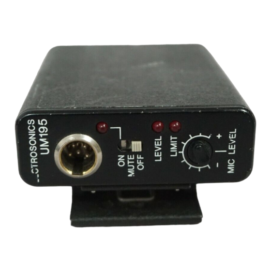
Figure 2 - UM195 Controls and Functions INPUT JACK The input on the UM195 accommodates virtually every lavalier, hand-held or shotgun microphone available. Use a Switchcraft TA5F connector on the cord. See the separate sheet titled "UM195 Input Jack Configuration"... - Page 7 The belt clip may be removed for special applications by removing one screw. USE ONLY THE SCREW THAT IS SUPPLIED The circuitry is tightly packed into this unit. A longer screw will permanently damage the transmitter! 50 Ohm Antenna Port Figure 3 - UM195, UHF Antenna Location...
-
Page 8: Battery Installation
Figure 4 - UM195 Battery Compartment Door Insert the battery correctly and close the cover by pressing the door closed and across, reversing the opening procedure illustrated above. If the battery is inserted incorrectly, the door will not close. Do not force the door... -
Page 9: Operating Instructions
OPERATING INSTRUCTIONS Install a fresh battery according to the instructions on the previous page. Insert the microphone plug into the input jack, aligning the pins; be sure that the connector locks in. Attach the antenna to the jack on the bottom of the transmitter. Turn the power switch to the "MUTE"... -
Page 10: M195 Input Jack Wiring
CONFIGURATION." VHF transmitters use the shield of the microphone cord as the antenna. The UHF UM195 uses a 1/4 wave flexible wire to radiate the RF signal. There is really not much difference between these two approaches, with respect to the effect of the RF on the microphone capsule. -
Page 11: Troubleshooting
TROUBLESHOOTING Before going through the following chart, be sure that you have a good battery in the transmitter. It is important that you follow these steps in the sequence listed. SYMPTOM POSSIBLE CAUSE TRANSMITTER BATTERY LED OFF 1) Battery is inserted backwards. 2) Battery is dead. -
Page 12: Specifications And Features
SPECIFICATIONS AND FEATURES Operating frequencies: UM195: 470 to 608 MHz RF Power output: UM195: 100 mW (nominal) Pilot tone: 32.768 kHz (± 2Hz); 5kHz deviation ± .002% Frequency stability: ± 75 kHz (max) Deviation: Spurious radiation: 50 dB below carrier... -
Page 13: Service And Repair
There are no adjustments inside that will make a malfunctioning unit start working. LECTROSONICS’ service department is equipped and staffed to quickly repair your equipment. In-warranty repairs are made at no charge in accordance with the terms of the warranty. Out of warranty repairs are charged at a modest flat rate plus parts and shipping. -
Page 14: Limited One Year Warranty
This warranty applies only to items returned to us, shipping costs prepaid, within one year from the date of purchase. This warranty gives you specific legal rights. You may have additional legal rights which vary from state to state. LECTROSONICS, INC. 581 LASER ROAD RIO RANCHO, NM 87124 USA July 6, 1999...
Need help?
Do you have a question about the UM195 and is the answer not in the manual?
Questions and answers