Advertisement
Advertisement
Table of Contents

Related Manuals for Chicago Electric Professional Series 60608


Summary of Contents for Chicago Electric Professional Series 60608
-
Page 2: Table Of Contents
Table of Contents Safety ............3 Maintenance ..........14 Specifications ..........7 Parts List and Diagram ......18 Setup ............8 Assembly Diagram ........19 Operation ........... 11 Warranty ............ 20 WARNING SYMBOLS AND DEFINITIONS This is the safety alert symbol. It is used to alert you to potential personal injury hazards. Obey all safety messages that follow this symbol to avoid possible injury or death. - Page 3 IMPORTANT SAFETY INFORMATION General Tool Safety Warnings WARNING Read all safety warnings and instructions. Failure to follow the warnings and instructions may result in electric shock, fire and/or serious injury. Save all warnings and instructions for future reference. 1. KEEP GUARDS IN PLACE and in working order. 11.
-
Page 4: Tile Saw Safety Warnings
Grounding Instructions TO PREVENT ELECTRIC SHOCK AND DEATH FROM INCORRECT GROUNDING WIRE CONNECTION READ AND FOLLOW THESE INSTRUCTIONS: 110-120 V~ Grounded Tools: Tools with Three Prong Plugs 1. In the event of a malfunction or breakdown, 6. Repair or replace damaged or worn cord immediately. grounding provides a path of least resistance for electric current to reduce the risk of electric shock. - Page 5 f. Spreader – A metal plate that follows the 12. To avoid the possibility of the tool plug or receptacle saw blade to keep the kerf (gap) from closing getting wet, position tile saw to one side of a on the saw blade. Spreaders, except riving wall mounted receptacle to prevent water from knives, must be aligned to the blade after dripping onto the receptacle or plug.
- Page 6 ADDITIONAL TILE SAW SAFETY WARNINGS 24. Industrial applications must follow OSHA guidelines. 19. DO NOT OPERATE WITH ANY GUARD DISABLED, 25. Maintain labels and nameplates on the tool. DAMAGED, OR REMOVED. Moving guards These carry important safety information. must move freely and close instantly. If unreadable or missing, contact Harbor Freight Tools for a replacement.
-
Page 7: Safety
Vibration Safety This tool vibrates during use. Repeated or long-term 2. Do not smoke during use. Nicotine reduces exposure to vibration may cause temporary or permanent the blood supply to the hands and fingers, physical injury, particularly to the hands, arms and increasing the risk of vibration-related injury. -
Page 8: Setup
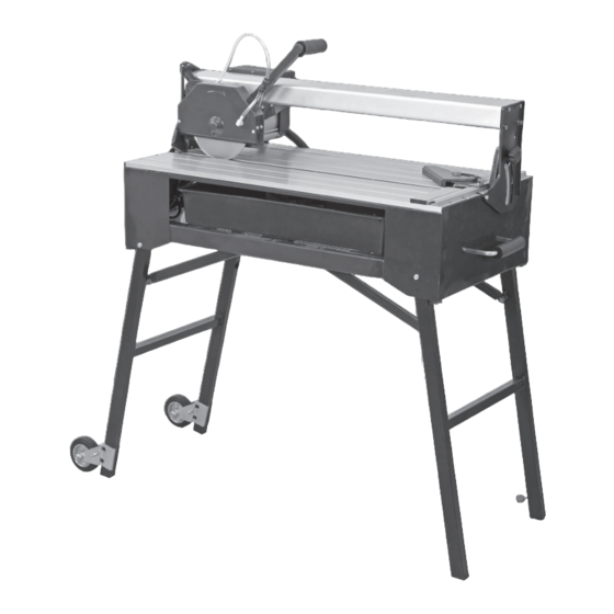
Setup - Before Use: Read the ENTIRE IMPORTANT SAFETY INFORMATION section at the beginning of this manual including all text under subheadings therein before set up or use of this product. Functions Miter Gauge Blade (sold separately) Water Tray Blade Guard Handle Table Circuit... - Page 9 ASSEMBLY TO PREVENT SERIOUS INJURY FROM ACCIDENTAL OPERATION: Turn the Power Switch of the tool to its “OFF” position and unplug the tool from its electrical outlet before assembling or making any adjustments to the tool. Note: For additional information regarding the parts listed in the following pages, refer to the Assembly Diagram near the end of this manual.
- Page 10 Attaching Locking Knobs 1. Align the Right Guide Rail Stand (111) Right Guide as shown in Figure 6, right. Rail Stand T-Knob (107) (111) 2. Remove the shipping screw and attach one Locking Knob (75) through the slot in the Right Guide Rail Stand (111) and into the threaded hole as shown.
-
Page 11: Operation
Operating Instructions Read the ENTIRE IMPORTANT SAFETY INFORMATION section at the beginning of this manual including all text under subheadings therein before set up or use of this product. TOOL SET UP TO PREVENT SERIOUS INJURY FROM ACCIDENTAL OPERATION: Turn the Power Switch of the tool to its “OFF” position, remove the key, and unplug the tool from its electrical outlet before assembling or making any adjustments to the tool. -
Page 12: Miter Adjustment
Miter Adjustment 1. Loosen the T-Knob (103A) on the Miter Gauge (102) and position the Miter Gauge at the Table Cutting Slot desired angle. Retighten the T-Knob. 2. To adjust the gap between the Miter Gauge (102) and the cutting slot in the Table, loosen Miter Gauge Miter Gauge the T-Knob (103B) on the Miter Gauge... -
Page 13: General Operating Instructions
Filling and Draining Water Tray 1. Fill Water Tray (60) before every use with enough clean, cold water to submerge 3/4 of the Water Pump (51). Do not overfill the Tray. Drain Plug (62) 2. To drain the Water Tray (60) place a large bucket under the Drain Plug (62). -
Page 14: Maintenance
Maintenance and Servicing Procedures not specifically explained in this manual must be performed only by a qualified technician. TO PREVENT SERIOUS INJURY FROM ACCIDENTAL OPERATION: Turn the Power Switch of the tool to its “OFF” position, remove the key, and unplug the tool from its electrical outlet before performing any inspection, maintenance, or cleaning procedures. -
Page 15: Troubleshooting
Troubleshooting Problem Possible Causes Likely Solutions Tool will not start. 1. Cord not connected. 1. Check that cord is plugged in. 2. No power at outlet. 2. Check power at outlet. If outlet is unpowered, turn off tool and check circuit breaker. If breaker is tripped, make sure circuit is right capacity for tool and circuit has no other loads. - Page 16 PLEASE READ THE FOLLOWING CAREFULLY THE MANUFACTURER AND/OR DISTRIBUTOR HAS PROVIDED THE PARTS LIST AND ASSEMBLY DIAGRAM IN THIS MANUAL AS A REFERENCE TOOL ONLY. NEITHER THE MANUFACTURER OR DISTRIBUTOR MAKES ANY REPRESENTATION OR WARRANTY OF ANY KIND TO THE BUYER THAT HE OR SHE IS QUALIFIED TO MAKE ANY REPAIRS TO THE PRODUCT, OR THAT HE OR SHE IS QUALIFIED TO REPLACE ANY PARTS OF THE PRODUCT.
- Page 17 Record Product’s Serial Number Here: Note: If product has no serial number, record month and year of purchase instead. Note: Some parts are listed and shown for illustration purposes only, and are not available individually as replacement parts. Item 60608 For technical questions, please call 1-800-444-3353.
-
Page 18: Parts List And Diagram
Parts List and Diagram Parts List Part Description Part Description Part Description Bolt M6 x 30 Flap Holder Bolt M6 x 20 Spring Washer Water Hose Connector Work Table Pad Flat Washer Rubber Flap Work Table (A) Sliding Handle Bolt M6 x 12 Water Tube Cover Adaptor Plastic Insert Screw M4 x 40... -
Page 19: Assembly Diagram
Assembly Diagram Item 60608 For technical questions, please call 1-800-444-3353. Page 19... -
Page 20: Warranty
Limited 90 Day Warranty Harbor Freight Tools Co. makes every effort to assure that its products meet high quality and durability standards, and warrants to the original purchaser that this product is free from defects in materials and workmanship for the period of 90 days from the date of purchase.
Need help?
Do you have a question about the Professional Series 60608 and is the answer not in the manual?
Questions and answers