Table of Contents
Advertisement
Quick Links
Advertisement
Table of Contents

Related Manuals for Sans Digital ACCUSTOR AS212X6


Summary of Contents for Sans Digital ACCUSTOR AS212X6
- Page 1 ACCUSTOR AS212X6 QUICK INSTALLATION GUIDE v1.0...
-
Page 2: Table Of Contents
Table of Contents Chapter 1 Introduction ....................3 Features ....................................4 Technical Specifications ............................... 5 Unpacking the JBOD Expansion Chassis ......................6 Identifying Parts of the Expansion Chassis ......................7 1.4.1 Front View ................................7 1.4.2 Rear View .................................. 8 1.4.3 Expansion Drawer .............................. -
Page 3: Chapter 1 Introduction
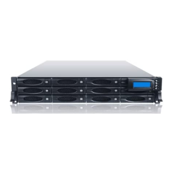
Chapter 1 Introduction Sans Digital AccuSTOR The AccuSTOR JBOD Enclosure is a 19-inch 2U 12 bays rackmount JBOD unit. It features the latest SASII (6Gb/s) interface and designed to fit in with the environments which needed highly reliable and relentless data growth. The JBOD Enclosure is also a versatile SAS2 / SATA3 Disk Expansion system, ideal for high capacity and scalability storage in IT demands. -
Page 4: Features
1.1 Features Modular architecture Redundant hot-swappable components, power and cooling modules Easy-to-use and maintenance Power Supply Power Supply and cooling system contained in 1 module for efficient cooling 300W power supplies to meet the future HDD power consumption Enclosure Hardware expansion slots keep you up-to-date on the latest technologies Incorporates a cableless design for maximum signal integrity Utilizes industry-standard SCSI Enclosure Services to monitor enclosure and disk environmental conditions... -
Page 5: Technical Specifications
1.2 Technical Specifications Form Factor 2U 19" rackmount chassis Host Bus Interface Two 4x mini SAS (6Gb/s) Expansion Bus Interface Two 4x mini SAS (6Gb/s) Disk Bus Interface 6Gb/s SAS , 6Gb/s SATA Backplane 6Gb/s SAS/SATA # of Hot Swap Trays Tray Lock Yes, with Lock Indicator Disk Status Indicator... -
Page 6: Unpacking The Jbod Expansion Chassis
1.3 Unpacking the JBOD Expansion Chassis The package contains the following items: • JBOD Expansion Chassis • Two power cords • One serial cable (phone-jack to DB9) • One external Mini SAS cable SFF-8088 to SFF-8088 • Installation Reference Guide •... -
Page 7: Identifying Parts Of The Expansion Chassis
1.4 Identifying Parts of the Expansion Chassis The illustrations below identify the various parts of the expansion chassis. 1.4.1 Front View User Manual... -
Page 8: Rear View
1.4.2 Rear View 1.4.3 Expansion Drawer User Manual... - Page 9 SAS IN Ports (A and B): SAS cable must be connected to these ports and to the SAS HBA, or other Expansion Chassis’s SAS Expansion Port, if this chassis is connected in daisy-chain. SAS IN Link LED: Green indicates SAS IN Port has connected or linked. SAS IN Access LED: Blue indicates SAS IN Port is being accessed.
-
Page 10: Power Supply / Fan Module (Psfm)
1.5 Power Supply / Fan Module (PSFM) Every JBOD contains two 300W Power Supply / Fan Modules. All PSFMs are inserted into the rear of the chassis. 1.5.1 PSFM Panel The Power Supply/Fan Module panel has: Power On/Off Switch, the AC Inlet Plug, and a Power On/Fail Indicator showing the Power Status LED, indicating ready or fail. -
Page 11: Power Supply Module Led
1.5.2 Power Supply Module LED When the power cord connected from main power source is inserted to the AC Power Inlet, the power status LED becomes RED. When the switch of the PSFM is turned on, the LED will turn GREEN. When the Power On/Fail LED is GREEN, the PSFM is functioning normally. -
Page 12: Lcd Display Panel
1.6 LCD Display Panel 1.6.1 LCD Panel LED Parts Function Power LED Green indicates power is ON. If one of the redundant power Power Fail LED supply unit fails, this LED will turn to RED and alarm will sound. Turn RED when fan 1 or 2 fails, or speed is lower than 3000 RPM. -
Page 13: Lcd Panel Function Buttons
1.6.2 LCD Panel Function Buttons Parts Function Up and Down Use the Up or Down arrow keys to go through the information on the Arrow buttons LCD screen. This is also used to move between each menu. This is used to enter the option Select button you have selected. -
Page 14: Menu Diagram
1.6.3 Menu Diagram Model-Name Chassis ID:0 F/W V 1.1.7J Disk Status ID:001-12 > S 1*0* 33C S 2*0* 32C S 11*0* 31C S 12*0* 30C Power Status Good > PSU-A: Good PSU-B: Good FAN Status Good > MF/PSU-A: 3409 RPM MF/PSU-B: 3479 RPM Voltage Status Good... -
Page 15: Drive Carrier Module
1.7 Drive Carrier Module The Drive Carrier Module houses a 3.5 inch hard disk drive. It is designed for maximum airflow and incorporates a carrier locking mechanism to prevent unauthorized access to the HDD. 1.7.1 Disk Drive Status Indicators Every Drive Carrier has 2 status indicator lights. One indicator light is used for Power On/Error. -
Page 16: Drive Carrier Lock Indicator
1.7.2 Drive Carrier Lock Indicator Every Drive Carrier is lockable and is fitted with a lock indicator to indicate whether or not the carrier is locked into the chassis or not. Each carrier is also fitted with an ergonomic handle for easy carrier removal. Drive Carrier is unlocked When the Lock Groove is vertical, then the Drive Carrier is unlocked. -
Page 17: Chapter 2 Installation Of Expansion Chassis
Chapter 2 Installation of Expansion Chassis 2.1 Installing hard Drives The expansion chassis supports hot-swapping allowing you to install or replace a hard drive while the expansion chassis is running. Press Make sure the Lock Groove is in unlocked position. Press the Carrier Open button and the Drive Carrier handle will flip open. - Page 18 Install the mounting screws on the bottom part to secure the drive in the disk tray. Slide the tray into a slot. Close the handle until you hear the latch click into place. User Manual...
-
Page 19: Setting The Dip Switch Of Jbod Controller
2.2 Setting the DIP Switch of JBOD Controller NOTE: Depending on the SAS RAID card used in the Host Server, the DIP switch must be set according to the tables below. DIP Switch Setting SAS RAID Card Note 0 0 1 1 0 0 0 0 Areca 0 1 1 1 0 0 0 0 LSI (Internal ports) - Page 20 Steps: 1. Remove the Expansion Drawer from the enclosure. 2. Configure the DIP Switch in the JBOD controller to the appropriate setting. Note that 0 is “ON” and 1 is “OFF”. Example settings (LSI): SWITCH DIP SWITCH SETTING 3. Reinsert the Expansion Drawer into the enclosure. User Manual...
-
Page 21: Chapter 3 Jbod Firmware Upgrade
Chapter 3 JBOD Firmware Upgrade IMPORTANT: Before upgrade the JBOD firmware, please shut down server first or make sure no array setting on the JBOD disks. The new Firmware will effective after JBOD power cycle. Steps: 1. Used RS-232 Port (Phone jack to DB9) link ProSun SAS JBOD, in command line please type “system upgrade”, than press “Enter”. - Page 22 2. Select Transfer & Send File. You must finish within 25 seconds 3. Select your firmware file path, and select Xmodem in the communication protocol, and click transfer button. User Manual...
- Page 23 4. Wait for the transfer of file to complete. User Manual...
- Page 24 5. When the transfer and firmware update is complete, please power cycle the JBOD. 6. In command line, type “system info”, you can see the Expander firmware version. User Manual...
Need help?
Do you have a question about the ACCUSTOR AS212X6 and is the answer not in the manual?
Questions and answers