Table of Contents
Advertisement
Quick Links
2
1
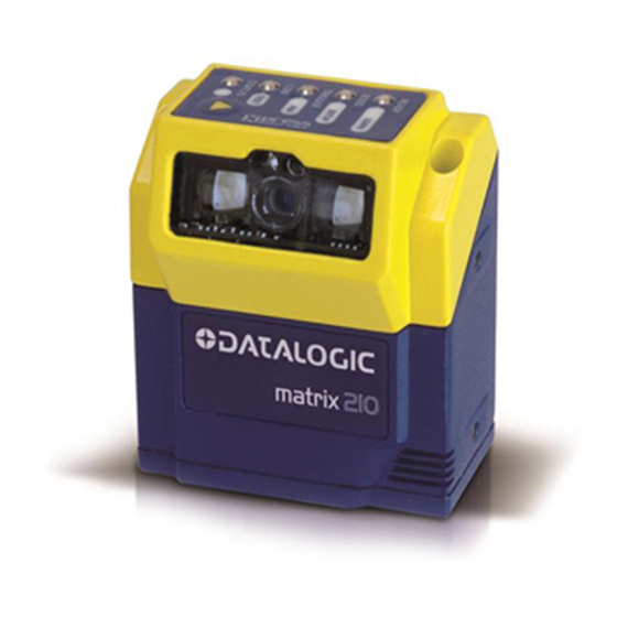
Mounting Holes (4)
1
"Power ON" LED
2
This manual illustrates a Stand Alone application. For other types of installations, such as ID-NET™, Fieldbus,
Pass-Through, Multiplexer Layout, etc. and for a complete reader configuration using the VisiSet™ configuration
program, refer to the Matrix 210™ Reference Manual available on the DVD and also downloadable from the Web at
www.automation.datalogic.com.
NOTE
Matrix 210™
QUICK REFERENCE GUIDE
3
4
Figure A
Ethernet Network Presence
3
LED
(for Ethernet Models)
HMI X-PRESS™ Interface
4
5
5
6
6
1
Reading Window
Device Class Labels
Advertisement
Table of Contents

Related Manuals for Datalogic Matrix 210


Summary of Contents for Datalogic Matrix 210
- Page 1 This manual illustrates a Stand Alone application. For other types of installations, such as ID-NET™, Fieldbus, Pass-Through, Multiplexer Layout, etc. and for a complete reader configuration using the VisiSet™ configuration program, refer to the Matrix 210™ Reference Manual available on the DVD and also downloadable from the Web at www.automation.datalogic.com.
- Page 2 MATRIX 210™ QUICK GUIDE UPDATES AVAILABILITY UK/US The latest drivers and documentation updates for this product are available on Internet. Log on to: www.automation.datalogic.com Su Internet sono disponibili le versioni aggiornate di driver e documentazione di questo prodotto. Collegarsi a: www.automation.datalogic.com Les versions mises à...
-
Page 3: Services And Support
- Material Return Authorization LEGAL NOTICES © 2011 Datalogic Automation S.r.l. ALL RIGHTS RESERVED. Protected to the fullest extent under U.S. and international laws. Copying, or altering of this document is prohibited without express written consent from Datalogic Automation S.r.l. -
Page 4: Step 1 - Connect The System
Figure 1 – Matrix 210™ 25-Pin Model in a Stand Alone Layout CBX100/CBX500 Pinout for Matrix 210™ 25-Pin Models The table below gives the pinout of the CBX100/CBX500 terminal block connectors. Use this pinout when the Matrix 210™ reader is connected by means of the CBX100/CBX500:... - Page 5 MATRIX 210™ QUICK GUIDE CBX100/500 Terminal Block Connectors Power Outputs Power Supply Input Voltage + Power Source - Outputs Power Supply Input Voltage - Power Reference - Outputs Earth Protection Earth Ground Output 1 + Output 1 - Inputs Output 2 + Power Source –...
- Page 6 The table below gives the pinout of the 25-pin male D-sub connector for connection to the power supply and input/output signals. Use this pinout when the Matrix 210™ reader is connected by means of the 25-pin connector: 25-pin D-sub male connector pinout...
- Page 7 Files\USB Virtual COM Port Drivers directory on the VisiSet Mini-DVD. NOTE The USB Virtual COM Port Driver allows sending serial data using the Matrix 210™ USB port. A different virtual COM Port will be assigned to each connected reader. Installing the USB Virtual COM port drivers: Double-click on the following file to launch the USB Virtual COM Port Driver Installer.
- Page 8 MATRIX 210™ QUICK GUIDE From the "Advanced Settings for COMx" dialog: • Expand the "COM Port Number" menu and select a new COM Port number if desired (optional). • Set the "BM Options" -> "Latency Timer" (msec) parameter to 1.
- Page 9 MATRIX 210™ QUICK GUIDE Matrix 210™ USB models can be connected in a Point-to-Point layout to a local host through their USB cable. No external power supply is necessary. The default baud rate is 115200. To maximize data transfer you can set it up to 921600 by configuring the reader though the Communication parameters via VisiSet™.
-
Page 10: Step 2 - Mount And Position The Reader
STEP 2 – MOUNT AND POSITION THE READER To mount the Matrix 210™, use the mounting bracket to obtain the most suitable position for the reader. Two of the most common mounting configurations are shown in the figures below. Other mounting solutions are provided in the Matrix 210™... - Page 11 MATRIX 210™ QUICK GUIDE When mounting the Matrix 210™ take into consideration these three ideal label position angles: Pitch or Skew 10° to 20° and Tilt 0°, although the reader can read a code at any tilt angle. Assure at least 10°...
- Page 12 MATRIX 210™ QUICK GUIDE STEP 3 – AIM THE READER Matrix 210™ provides a built-in aiming system to aid reader positioning. The aiming system is accessed through the X-PRESS™ Interface. Power the reader on. During the reader startup (reset or restart phase), all the LEDs blink for one second. On the connector side of the reader near the cable, the “POWER ON”...
-
Page 13: Step 4 - X-Press™ Configuration
STEP 4 – X-PRESS™ CONFIGURATION Once Matrix 210™ is positioned with respect to the code (step 3), you can configure it for optimal code reading relative to your application. This configuration can be performed either through the X-PRESS™ Interface or the VisiSet™ configuration program. - Page 14 Learn Function Exit the Setup function by pressing the X-PRESS™ push button once. If you have used this procedure to configure Matrix 210™ go to step 7. RESET READER TO FACTORY DEFAULT (OPTIONAL) If it ever becomes necessary to reset the reader to the factory default values, you can perform this procedure by holding the X- PRESS™...
-
Page 15: Step 5 - Installing Visiset™ Configuration Program
MATRIX 210™ QUICK GUIDE STEP 5 – INSTALLING VISISET™ CONFIGURATION PROGRAM ™ VisiSet is a Datalogic reader configuration tool providing several important advantages: • Setup Wizard for rapid configuration and new users; • Defined configuration directly stored in the reader;... -
Page 16: Step 6 - Configuration Using Setup Wizard
MATRIX 210™ QUICK GUIDE STEP 6 – CONFIGURATION USING SETUP WIZARD The Setup Wizard option is advised for rapid configuration or for new users. It allows reader configuration in a few easy steps. Select the Setup Wizard button from the Main menu. - Page 17 MATRIX 210™ QUICK GUIDE Place the application specific code in front of the reader at the correct reading distance (see step 2 and the Reading Features table in the Appendix of this Quick Reference Guide). Press the "Positioning" button. The reader continuously acquires images and gives visual feedback in the view image window.
- Page 18 MATRIX 210™ QUICK GUIDE Select a Calibration Mode choice and press the "Calibrate" button. The reader flashes once acquiring the image and auto determines the best exposure and gain settings. If the code symbology is enabled by default, the code will also be decoded.
- Page 19 MATRIX 210™ QUICK GUIDE Select a Code Setting Mode choice and press the "Code Setting" button. The Setup Result section of the Setup Wizard window shows the code type results and parameter settings. Setup Result...
- Page 20 MATRIX 210™ QUICK GUIDE Select a Saving Options choice and press the "Save" button. Close the Setup Wizard. If your application has been configured using the VisiSet™ Setup Wizard, your reader is ready. If necessary you can use VisiSet™ for advanced reader configuration.
-
Page 21: Step 7 - Test Mode
MATRIX 210™ QUICK GUIDE STEP 7 – TEST MODE Use a code suitable to your application to test the reading performance of the system. Alternatively, you can use the Datalogic 1D/2D Test Chart (Code 39, Data Matrix ECC 200). Enter the Test function by pressing and holding the X-PRESS™ push button until the Test LED is on. -
Page 22: Advanced Reader Configuration
ADVANCED READER CONFIGURATION For further details on advanced product configuration, refer to the complete Reference Manual on the installation Mini-DVD or downloadable from the web site through this link: www.automation.datalogic.com. The following are alternative or advanced reader configuration methods. ADVANCED CONFIGURATION USING VISISET™... -
Page 23: Host Mode Programming
The reader can also be setup for alternative layouts by reading programming barcodes. See the "Setup Procedure Using Programming Barcodes" printable from the Mini-DVD. CODE QUALITY VERIFICATION Matrix 210™ can be used as a Code Quality Verifier according to the ISO/IEC 15415, ISO/IEC 15416, AS9132, and AIM DPM Standards. - Page 24 MATRIX 210™ QUICK GUIDE APPENDIX X-PRESS™ is the intuitive Human Machine Interface designed to improve ease of installation and maintenance. Status and diagnostic information are clearly presented by means of the five colored LEDs, whereas the single push button gives immediate access to the following relevant functions: •...
-
Page 25: Reading Features
MATRIX 210™ QUICK GUIDE READING FEATURES Focus Field of View Typ. Linear and 2D Code Resolution Reading Distance Distance Stacked Code mm (mils) mm (in) MODELS Resolution mm mm (in) mm (in) min. max. (mils) 16.5 × 10.5 Max. 0.076 (3) 28 (1.10) -
Page 26: Technical Features
MATRIX 210™ QUICK GUIDE TECHNICAL FEATURES ELECTRICAL FEATURES Matrix 210 21x-x0x models Matrix 210 21x-x1x models Matrix 210 21x-x2x models Power Supply Voltage 10 to 30 Vdc 10 to 30 Vdc 5 Vdc 0.35 to 0.13 A, 3.9 W max 0.4 to 0.15 A, 4.5 W max... -
Page 27: Environmental Features
• POSTNET (+BB) • Matrix 2 of 5 • Intelligent Mail (this symbology requires an activation • Interleaved 2 of 5 • Swedish Post procedure – contact your local Datalogic Automation distributor for details) Operating Mode ONTINUOUS HASE X-PRESS™ Human Machine Interface Configuration Methods Windows-based SW (VisiSet™) via serial, Ethernet or USB link... -
Page 28: User Interface
MATRIX 210™ QUICK GUIDE CODE QUALITY VERIFICATION Standard Supported Symbologies ISO/IEC 16022 Data Matrix ECC 200 ISO/IEC 18004 QR Code ISO/IEC 15415 Data Matrix ECC 200, QR Code ISO/IEC 15416 Code 128, Code 39, Interleaved 2 of 5, Codabar, Code 93, EAN-8/13, UPC-A/E... -
Page 29: Mechanical Dimensions
MATRIX 210™ QUICK GUIDE MECHANICAL DIMENSIONS 25.0 25.0 [0.29] [0.98] [0.29] [0.98] [0.36] M3X4 n°4 OPTICAL AXIS [1.76] OPTICAL AXIS [0.25] [1.97] [2.13] [in] Figure 17 – Matrix 210™ Overall Dimensions - Straight and 90° Reading Window Models... - Page 30 MATRIX 210™ QUICK GUIDE ST-336 bracket for Straight Reading Window Model ST-337 bracket for 90° Reading Window Model 60° 30° 30° 90° 60° 18.5 12.5 Ø 6.2 n°2 [0.73] [1.50] [0.49] [2.52] [0.98] [1.46] 60° 30° Ø 6.2 n°3 30°...
-
Page 31: Emc Compliance
Additional patents pending. COMPLIANCE See the Matrix 210™ Reference Manual for the Declaration of Conformity. Only connect Ethernet and dataport connections to a network which has routing only within the plant or building and no routing outside the plant or building. -
Page 32: Power Supply
FCC COMPLIANCE Modifications or changes to this equipment without the expressed written approval of Datalogic could void the authority to use the equipment. This device complies with PART 15 of the FCC Rules. Operation is subject to the following two conditions: (1) This device may not cause harmful interference, and (2) this device must accept any interference received, including interference which may cause undesired operation.
Need help?
Do you have a question about the Matrix 210 and is the answer not in the manual?
Questions and answers