Table of Contents
Advertisement
Table of Content
Quick Installation ................................................. 4
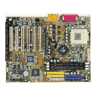
1.1 Layout............................................................................ 4
1.2 Item Checklist ................................................................ 5
1.3 Jumpers ........................................................................ 5
1.4 Connectors ................................................................... 8
1.5 Form Factor ................................................................. 16
Feature ................................................................ 18
2.1 Motherboard Components Placement ..................... 18
2.2 Block Diagram ............................................................. 20
2.3 Specifications ............................................................. 21
Hardware Setup ................................................. 24
3.1 Before Installation ...................................................... 24
3.2 Install the Processor ................................................... 25
3.3 Install Memory Modules ............................................. 28
3.4 ATX Power Supply connector ................................... 30
3.5 Back Panel ................................................................... 32
FB11351020000
KK266/KK266-R Version 1.1A
1
Advertisement
Table of Contents

Related Manuals for IWILL KK266


Summary of Contents for IWILL KK266
-
Page 1: Table Of Contents
2.3 Specifications ............. 21 Hardware Setup ..........24 3.1 Before Installation ............24 3.2 Install the Processor ........... 25 3.3 Install Memory Modules ..........28 3.4 ATX Power Supply connector ........30 3.5 Back Panel ..............32 FB11351020000 KK266/KK266-R Version 1.1A... - Page 2 4.8 Power Management Setup ......... 62 4.9 PnP/ PCI Configurations ..........69 4.10 PC Health Status ............72 4.11 Iwill Smart Setting ............. 73 4.12 Load Fail Safe Defaults ..........76 4.13Load Optimized Defaults ........... 77 4.14 Set Supervisor/ User Password Setting ....78 4.15 Save &...
- Page 3 Chapter 1 Quick Installation 5.6 SPDIF/IN (SPDIF version only) ........ 108 5.7 Loopback (bypass) mode Setup ......112 Power Installar CD........... 116 6.1 Software Installation ..........116 6.2 How to use the Power installer CD ......117 6.3 How to make driver diskette ........117 6.4 Install Driver ..............
-
Page 4: Quick Installation
Chapter 1 Quick Installation 1 Quick Installation 1.1 Layout... -
Page 5: Item Checklist
Chapter 1 Quick Installation 1.2 Item Checklist [V ] The motherboard [V ] Operation manual [V ] ATA/66/100 cable [V ] Floppy cable [V ] Power Installer CD Optional ] USB riser kit ] Thermal Sensor for System ] Display Cache Riser Card ] Infrared port cable ] Display Cache Riser Card ] Optional Module (SPDIF version only) - Page 6 Chapter 1 Quick Installation 1.3.2 FSB select jumper 1.3.3 PCI compatibility jumper 1.3.4 VIO (JP10) jumper...
- Page 7 Chapter 1 Quick Installation 1.3.5 IDE RAID jumper(KK266-R Only) 1.3.6 Audio jumper...
-
Page 8: Connectors
Chapter 1 Quick Installation 1.4 Connectors 1.4.1 CPU fan header (J39) 1.4.2 Auxiliary fan header(J41) 1.4.3 System fan header (J40) - Page 9 Chapter 1 Quick Installation 1.4.4 Infrared connector (IR) 1.4.5 Wake-ON-LAN header...
-
Page 10: Smbus Connector
Chapter 1 Quick Installation 1.4.6 Wake On Moden 1.4.7 SmBus connector... - Page 11 Chapter 1 Quick Installation 1.4.8 ATX power connector (J37)
- Page 12 Chapter 1 Quick Installation 1.4.9 Front panel connector (J43)
- Page 13 Chapter 1 Quick Installation...
-
Page 14: Internal Usb Connector
Chapter 1 Quick Installation 1.4.10 Aux-In connector(Aux_IN) 1.4.11 CD_In connector(CD_IN) 1.4.12 Internal USB connector The motherboard has two USB ports onboard. The extra two USB support can only functionable with the additional USB riser kit. - Page 15 Chapter 1 Quick Installation 1.4.13SPDIF connector(Optional)
-
Page 16: Form Factor
Chapter 1 Quick Installation 1.5 Form Factor... - Page 17 Chapter 1 Quick Installation...
-
Page 18: Feature
Chapter 2 Feature 2 Features 2.1 Motherboard Components Placement... - Page 19 Chapter 2 Feature...
-
Page 20: Block Diagram
Chapter 2 Feature 2.2 Block Diagram... -
Page 21: Specifications
Chapter 2 Feature 2.3 Specifications Processor I/F (Socket A) Supports 1 processor through Socket A Supports DDR_200MHz FSB (Front Side Bus) Supports AMD Duron CPU from 600 MHz to 800 MHz Supports AMD Athlon (T-Bird) CPU from 750 MHz to 1.2GHz or higher. - Page 22 Supports Floppy interface Supports 16550A UART interface Supports ECP/EPP interface Supports PS2 interface Supports SIR interface Supports USB interface RAID onboard (KK266-R only) Supports 2 ATA100 channels Supports RAID Level 0/1 Supports Win9X/WinNT/Win2K/Linux Sound support C-Media HW Sound controller on board...
- Page 23 Chapter 2 Feature Expansion Slot, Sockets and Connectors One Socket 462 socket Three DIMM sockets One AGP slot Five PCI slots One AMR slot Two IDE connectors Two IDE RAID connectors One FDC connector Others ATX Form Factor 305mm x 235mm...
-
Page 24: Hardware Setup
Chapter 3 Hardware Setup Hardware Setup 3.1 Before Installation For installation, you may need some or all of the following tools: Medium size flat blade screwdriver Medium size Phillips head screwdriver A 3/16 inch nut driver or wrench o l l n i l t a l k i l... -
Page 25: Install The Processor
Chapter 3 Hardware Setup 3.2 Install the Processor... - Page 26 Chapter 3 Hardware Setup Step1: Locate the ZIF socket and open it by first pulling the lever of socket upward. Step2: Insert the CPU into the socket. Please keep the lever right angle when inserting CPU. Step3: When inserting the CPU please note the correct orientation as shown.
- Page 27 Chapter 3 Hardware Setup Step4: Push the lever down to close the socket. Step 5: Attach the heatsink onto the CPU. Step6: Push the clip of heatsink downward to hock the ear of socket firmly.
-
Page 28: Install Memory Modules
Chapter 3 Hardware Setup Step7: Finally, attach the fan cable to the CPU fan header FCPU. 3.3 Install Memory Modules The motherboard has three Dual Inline Memory Module (DIMM) sockets and supports the maximum memory size up to 1.5GB. These DIMM sockets only support 3.3V unbuffered SDRAM modules. - Page 29 Chapter 3 Hardware Setup Step 1:Open latches of DIMM socket Step 2:Proofread the RAM module to the DIMM Socket. Step 3:Insert the RAM module into the DIMM socket.
-
Page 30: Atx Power Supply Connector
Chapter 3 Hardware Setup Step 4:Press the latches into the notches of the RAM module. 3.4 ATX Power Supply Connector 3.4.1 Power on procedures t p i c t i . f f t e l c t i c t i o l l t i n... - Page 31 Chapter 3 Hardware Setup l l i l l i l l i 3.4.2 Power off procedures t p i l l a c i l c t i c i t y l l l l a...
-
Page 32: Back Panel
Chapter 3 Hardware Setup 3.5 Back Panel , s t l a i . t r & t n i e l l e l l c i t c i t i d i o l l o l l t t u l l i... - Page 33 Chapter 3 Hardware Setup...
-
Page 34: Bios Setup
Chapter 4 BIOS Setup BIOS Setup 4.1 PhoenixNet Introduction PhoenixNet is a service that provides PC users with best-of-breed, free, software services to support their PC hardware and software and to turn their computer into a powerful tool for communication, entertainment, education and business 4.1.1 Internet Launch System The PhoenixNet Internet Launch System (ILS) is a patent-... - Page 35 Chapter 4 BIOS Setup 4.1.3 PhoenixNet Online Services & i t n r i v i t c ¡K : s l...
- Page 36 Chapter 4 BIOS Setup 4.1.4 User Boot f n i 4.1.5 Internet Access & t l u & l i a s l l c i l . l i...
-
Page 37: Bios Setup
4.2.1 Upgrade BIOS The BIOS can be upgraded from a diskette with the Award Flash utility — AWDFLASH.EXE. The BIOS image file, and update utility are available from IWILL’s WEB site: www. iwill.net 4.2.2 Enter BIOS setup program Power-on the system by either pressing the Power-On button, or by using any of the power-on features provided by the motherboard. - Page 38 Chapter 4 BIOS Setup 4.2.3 Using BIOS setup program Move to the previo Down Move to the next f Move to the field o Left side Move to the field o Right side Quit from setup pr saving changes, o <Esc>...
-
Page 39: Main Menu
Chapter 4 BIOS Setup 4.3 Main Menu The main menu allows you to select from several setup pages. Use the arrow keys to select among these pages and press <Enter> key to enter the sub-menu. A brief description of each highlighted selection appears at the bottom of the screen. -
Page 40: Standard Cmos Features
Chapter 4 BIOS Setup 4.4 Standard CMOS Features 4.4.1Date This field specifies the current date. The date format is <month>, <day>, and <year>. 4.4.2 Time This field specifies the current time. The time format is <hour>, <minute>, and <second>. The time is calculated based on the 24-hour (military-time) clock. - Page 41 Chapter 4 BIOS Setup 4.4.3 IDE Primary Master / Primary Slave / Secondary Master / Secondary Slave Press “Enter” to enter next page for detail hard drive setting. 4.4.3.1 IDE HDD Auto-Detection Auto-Detect the HDDs Capacity, and its parameters, ex: Cylinder, Head and Sector. 4.4.3.2 IDE Primary Master / Primary Slave / Secondary Master / Secondary Slave This field specifies type of drive that corresponds to...
- Page 42 Chapter 4 BIOS Setup 4.4.3.5 Cylinders Set the number of cylinders for this hard disk. 4.4.3.6 Heads Set the number of read/write heads 4.4.3.7 Precomp Setting a value of 65535 means no hard disk 4.4.3.8 Sectors Set the number of sectors per track 4.4.4 Drive A / Drive B This field specifies the traditional type of floppy drives.
- Page 43 Chapter 4 BIOS Setup v i r 4.4.6 Video i f i f i c f i c i f i 4.4.7 Halt On l l i , l l l l i , l l l l i , l l...
-
Page 44: Base Memory
Chapter 4 BIOS Setup 4.4.8 Base Memory The POST (Power-On Self Test) determines the amount of base (conventional) memory installed in the system. The value of the base memory is typically 640K. This field has no options. 4.4.9 Extended Memory The BIOS determines how much extended memory is present during the POST. -
Page 45: Advanced Bios Features
Chapter 4 BIOS Setup 4.5 Advanced BIOS Features... -
Page 46: Virus Warning
Chapter 4 BIOS Setup 4.5.1 Virus Warning When this function is enabled, the BIOS monitor the boot sector and partition table of the hard disk drive for any attempt at modification. If an attempt is made, the BIOS will halt the system and then display an error message. -
Page 47: Quick Power On Self Test
Chapter 4 BIOS Setup 4.5.5 Quick Power On Self Test This field allows the system to skip certain tests while booting. This will decrease the time needed to boot the system. 4.5.6 First / Secondary / Third / Other Boot Device The BIOS attempts to load the operating system from the devices in the sequence selected in these items. -
Page 48: Gate A20 Option
Chapter 4 BIOS Setup 4.5.11Gate A20 Option This field configures how the gate A20 is handled. The gate A20 is a device used to address memory above 1 MB. At first, the gate A20 was handled from a pin on the keyboard. While some keyboards still provide this support, it is more common, and much faster, for modern system chipsets to provide support for gate A20. -
Page 49: Security Option
Chapter 4 BIOS Setup 4.5.14Typematic Delay (Msec) When enabled, typematic delay allows you to select the time delay between when the key is first pressed and when the acceleration begins. 4.5.15Security Option This field configures how the system security is handled. It works conjunction with SETTING SUPERVISOR / USER PASSWORD page to control the security level of the system. -
Page 50: Video Bios Shadow
Chapter 4 BIOS Setup 4.5.18Video BIOS Shadow When enabled, the video BIOS will be copied to system memory and increase the video speed. 4.5.19C8000-CBFFF/CC000-CFFFF/D0000-D3FFF Shadow D4000-D7FFF/D8000-DBFFF/DC000-DFFFF Shadow , e l... -
Page 51: Advanced Chipset Features
Chapter 4 BIOS Setup 4.6 Advanced Chipset Features This setup page is used to specify advanced features available through the chipset. The default settings have been chosen carefully for most operating conditions. DO NOT change the value of any field in this setup page without full understanding. -
Page 52: Sdram Cycle Length
Chapter 4 BIOS Setup DRAM Settings The first chipset settings deal with CPU access to dynamic random access memory (DRAM). The default timings have been carefully chosen and should only be altered if data is being lost. Such a scenario might well occur if your system had mixed speed DRAM chips installed. -
Page 53: Memory Hole
Chapter 4 BIOS Setup 4.6.4 Memory Hole In order to improve performance, certain space in memory is reserved for ISA cards. This memory must be mapped into the memory space below 16MB. 4.6.5PCI Dynamic Bursting When enabled, every write transaction goes to the write buffer, and burstable transactions will then burst on the PCI bus, and non-burstable transactions won’t burst on the PCI bus. -
Page 54: Video Ram Cacheable
Chapter 4 BIOS Setup 4.6.8 Video RAM Cacheable When enabled, access to the video memory located at A0000H to BFFFFH will be cached. 4.6.10 AGP Aperture Size This field specifies the size of system memory that can be used for AGP graphics aperture. 4.6.11AGP-4X Mode This item allows you to enable/disable the AGP-4X Mode. -
Page 55: Integrated Peripherals
Chapter 4 BIOS Setup 4.7 Integrated Peripherals... - Page 56 Chapter 4 BIOS Setup 4.7.1 On-Chip Primary IDE Channel 0 This field enables or disables the onboard IDE controller. 4.7.2 On-Chip SecondaryIDE Channel 1 This field enables or disables the onboard IDE controller. 4.7.3 Primary Master / Slave PIO Secondary Master / Slave PIO These fields configure the PIO (Programmable Input Output) transfer mode for each IDE devices.
-
Page 57: Init Display First
Chapter 4 BIOS Setup 4.7.4Primary Master / Slave UDMA Secondary Master / Slave UDMA If you select Auto, the IDE controller uses Ultra DMA 33/66 Mode to access Ultra DMA-capable IDE devices. 4.7.5 Init Display First This item allows you to decide which slot to activate first, either PCI slot or AGP slot. -
Page 58: Ide Hdd Block Mode
Chapter 4 BIOS Setup 4.7.6.4 SB DMA Use Select This item allows you to selec sound blaster DMA channel. 4.7.6.5 MIDI Port This item allows you to selec MIDI Port enable/ disable. , e l 4.7.6.6 MIDI Address Port This item allows you to selec MIDI Port I/O address. 4.7.6.7 Game port Address This item allows you to select game port enable/ disable. - Page 59 Chapter 4 BIOS Setup 4.7.9Onboard FDD Controller This field enables or disables the onboard floppy controller. 4.7.10Onboard Serial Port 1 / 2 These fields configure the onboard serial ports. There are several port addresses and IRQ channels to select from. c i t .
-
Page 60: Onboard Parallel Port
Chapter 4 BIOS Setup 4.7.11.2IR Duplex Mode When setting the field to either HPSIR or ASKIR, you must select the mode of receiving and transmitting signals. f l a l l u A second serial port is using a serial port bracket connected from the motherboard to an expansion slot opening. -
Page 61: Ecp Mode Use Dma
Chapter 4 BIOS Setup 4.7.14ECP Mode Use DMA When the Parallel Port Mode field is configured as ECP, it needs a DMA channel for data transfer. This field specifies the DMA channel for ECP parallel port use. 4.7.15Parallel Port EPP Type When the Parallel Port Mode field is configured as EPP, ECP+EPP mode, the EPP version needs to be specified. -
Page 62: Power Management Setup
Chapter 4 BIOS Setup 4.8 Power Management Setup Each power-saving mode has a respective timer. The value of the timer can be assigned or reloaded and it will count down to zero. When the timer equals to zero, the system will be forced into the related suspend or power-saving mode. -
Page 63: Power Management
Chapter 4 BIOS Setup 4.8.1Power Management This feature allows the user to select the default parameters for the power-saving mode. f i f y f i 4.8.1.1 APM HDD Power Down Timer This field specifies the time the system enters HDD power down. -
Page 64: Pm Control By Apm
Chapter 4 BIOS Setup 4.8.2 PM Control by APM When enabled, an Advanced Power Management (APM) protocol will be activated to handle the power-saving mode. 4.8.3 Video off Option This field specifies the method that video subsystem used for power saving. l l i 4.8.4 Video off Method c i t... -
Page 65: Wake Up Events
Chapter 4 BIOS Setup 4.8.6 PWR-Off Mode by PWR-BTTN This field specifies the function of power button. 4.8.7 Wake Up Events These are I/O events whose occurrence can prevent the system from entering a power-saving mode, or can awaken the system from such a mode. In effect, the system remains alert for anything that occurs to a device configured and recognized by the system, even when the system is in a power down mode. - Page 66 Chapter 4 BIOS Setup 4.8.7.1VGA When ON, your can set the VGA to awaken the system. 4.8.7.2 LPT & COM When On, any activity from one of the listed system peripheral devices or IRQs wakes up the system. 4.8.7.3 HDD & FDD When On, any activity from either hard disk drive or floppy disk drive wakes up the system.
- Page 67 Chapter 4 BIOS Setup another location, and this will power-on your PC. When using this feature, you must have a modem, and your PC must be turned off. 4.8.7.7 PWROn/Resume by Alarm When enabled, you can set the date and time to automatically power-on your PC (similar to an alarm clock).
- Page 68 Chapter 4 BIOS Setup 4.8.7.9IRQs Activity Monitoring When On, any event that occurs will awaken the system after it has powered-down.The following is a list of IRQ’s, or “Interrupt Requests,” which can be exempted much as the COM ports and LPT ports above can.
-
Page 69: Pnp/ Pci Configurations
Chapter 4 BIOS Setup 4.9 PnP/ PCI Configurations... -
Page 70: Pnp Os Installed
Chapter 4 BIOS Setup 4.9.1 PNP OS Installed The field specifies whether a Plug and Play operating system is installed. 4.9.2 Reset Configuration Data Normally, you leave this field Disabled. Select Enabled to reset Extended System Configuration Data (ESCD) when you exit Setup if you have installed a new add-on and the system reconfiguration has caused such a serious conflict that the operating system can not boot. - Page 71 Chapter 4 BIOS Setup 4.9.3.1 IRQ Resources When resources are controlled manually, assign each system interrupt a type, depending on the type of device using the interrupt. 4.9.3.1.1IRQ3/4/5/7/9/10/11/12/14/15 assigned to 4.9.3.2 DMA Resources 4.9.3.2DMA 0/1/ 3/ 5/ 6/ 7 assigned to 4.9.4 PCI / VGA Palette Snoop This field controls the ability of a primary PCI graphics controller to share a common palette with an ISA/VESA video...
-
Page 72: Pc Health Status
Chapter 4 BIOS Setup 4.10 PC Health Status This page is monitoring your status of computer. On the screen displays CPU/System temperature, FAN speed, and voltages. -
Page 73: Iwill Smart Setting
Chapter 4 BIOS Setup 4.11 Iwill Smart Setting... - Page 74 Chapter 4 BIOS Setup 4.11.1 Iwill MicroStepping MicroStepping Microstepping is Iwill's anther step forward to provides users a fuss free CPU frequency set up procedure. It contains two main functions, Auto Detecting CPUs speed and Micro Adjustable CPU FSB speed.
-
Page 75: Spread Spectrum
Chapter 4 BIOS Setup 4.11.2Spread Spectrum This item comfigures radiation emitted from the system. When enabled, system will release less radiation. , e l 4.11.3Vcore Voltage Setting 4.11.4BIOS-ROM Flash Protect The main function of BIOS-ROM Flash Protect prevents the virus of computers to destory the system of computers. When JP16 is set on 1-2 , the Flash ROM pretection mode will be controlled by this field. -
Page 76: Load Fail Safe Defaults
Chapter 4 BIOS Setup 4.12 Load Fail Safe Defaults When you press <Enter> on this item you get a confirmation dialog box with a message similar to: Pressing ‘Y’ loads the BIOS default values for the most stable, minimal-performance system operations. -
Page 77: Load Optimized Defaults
Chapter 4 BIOS Setup 4.13 Load Optimized Defaults When you press <Enter> on this item you get a confirmation dialog box with a message similar to:... -
Page 78: Set Supervisor/ User Password Setting
Chapter 4 BIOS Setup 4.14 Set Supervisor/ User Password Setting... - Page 79 Chapter 4 BIOS Setup These setup pages are used for password setting. When a password has been enabled and the Security Option field is set as Setup, you will be required to enter the password every time you try to enter BIOS Setup program. This prevents an unauthorized person from changing any part of your system configuration.
-
Page 80: Save & Exit Setup
Chapter 4 BIOS Setup 4.15 Save & Exit Setup Saves current CMOS value and exit BIOS setup program. -
Page 81: Exit Without Saving
Chapter 4 BIOS Setup 4.16 Exit Without Saving Abandons all CMOS value changes and exits BIOS setup program. -
Page 82: On Board Audio
Chapter 5 On board Audio 5 On board Audio The on board 4.1 channel PCI Audio on Iwill motherboards offer a new generation PCI audio solution: it utilizes the state-of-the-art CRL® 3D Audio technology (HRTF 3D positional audio), and supports Microsoft® Direct Sound ® 3D and Aureal®’s A3D®... -
Page 83: Audio Features
Chapter 5 On board Audio 5.1 Audio Features 5.1.1 Special Features 32 bit PCI bus master. Full duplex playback and recording, built-in 16 bits CODEC. HRTF 3D positional audio, supports both Direct Sound 3D® & A3D® interfaces, supports earphones, two and four channel speakers mode. -
Page 84: Driver Installation
Chapter 5 On board Audio 5.2 Driver Installation 5.2.1 DOS Installation Before beginning the installation, please make sure that your hard disk has sufficient space(min. 4MB). Insert the Power Installer CD into the CD-ROM Drive. i t u i t i l . - Page 85 Chapter 5 On board Audio l l a , e l l l i l l a v i r k i l : s i " t l u n i l , " t " " t " "...
- Page 86 Chapter 5 On board Audio 5.2.3 Win 95/98 Un-Installation In the cases you are experiencing some technical difficulties (the sound device is not function properly). It is suggested that you proceed with the un-install procedure: v i r . t i o l l l l a If you want to completely remove the drivers, you can also run...
- Page 87 Chapter 5 On board Audio S " " t r g i l S " " g " . " l i l c " t l u " a " t " s A " " d " t s i l v i r i "...
-
Page 88: The Audio Rack
Chapter 5 On board Audio 5.3 The Audio Rack 5.3.1 Introduction By means of a user-friendly interface (as easy as operating your home stereo system), this PCI audio rack provides you with the control over your PC’s audio functions, including the advantage of four speakers mode enable/ disable, and perfect digital sound ( SPDIF version ONLY) input / output. - Page 89 Chapter 5 On board Audio 5.3.2About Audio Rack The Audio Rack is consisted of several major components. 5.3.2.1 Control Center Controls the display of the PCI Audio Rack’s components. 5.3.2.2 MIDI Player Plays MIDI music files, and allows you to create your personal song playlists, and play the song files.
- Page 90 Chapter 5 On board Audio 5.3.4.1 Sel (or Trk) field: If you have multiple selections in your playlist, this shows the number of the current selection or CD track. 5.3.4.2 Current File or Track: The name of the current MIDI file, wave audio file, or CD track.
- Page 91 Chapter 5 On board Audio 5.3.5.1 Volume Control: Clicking on this button shows and allows you to use the output level controls. 5.3.5.2Recording Control: Clicking on this button shows and allows you use the input level controls. 5.3.5.3 Input and Output Level Sliders and Buttons: For each input or output signal type, the control slider controls the loudness whereas the horizontal slider controls the balance between the two speakers.
- Page 92 Chapter 5 On board Audio d Wave: Controls wave (voice) playback or the recording levels. e FM: Controls the FM music playback or the recording level. f Aux-in: Controls the Aux-in music play or the recording level. g PC-SPK: Controls the external PC speaker input level. h CD: Controls the CD drive output level, for CD drives configured to play their audio output through the PCs...
- Page 93 Chapter 5 On board Audio 5.3.5.4 Mute Buttons: Toggle between muting and enabling the signal. A button with a lit LED is enabled, and when it is not lit, it means it is mute. Several output signals can usually be enabled at once. 5.3.6 MP3 Player MP3 player can play both wave files and MP3 files.
-
Page 94: The 4 Speakers System
The settings’ window when one of the SPDIF functions is enabled. (SPDIF version ONLY) 5.3.7 The 4 Speakers System The on board audio on Iwill motherboards provide 2 wave channels (front/rear + subwoffer), known as the 4.1 speakers system. When games or application programs via DirectSound®... - Page 95 Chapter 5 On board Audio 5.3.7.2The positions of the speakers Put your speakers the way the following picture suggests, to deliver the best audio result. 5.3.7.3 The mixer setup There is a 4 speakers option in the volume control of the mixer, and when you enable this option, it means the rear speakers are connected to Line-in/Rear jack.
- Page 96 SONY® and Philips®. It is commonly used in audio industry now adays. 5.3.9 IWILL Opti-Link(SPDIF VERSION ONLY) Opti-Link™ is an optical in / out put module that allows users to export and inport audio signal with a superior qulaity.
- Page 97 Chapter 5 On board Audio 5.3.10Opt-Link Installation 5.3.11Optical SW Setting...
-
Page 98: The Application Program Setup
Chapter 5 On board Audio 5.4 The Application Program Setup(Please install) STEP 1:When the connection between devices and Opti-Link™ is done, please go to the Start menu and select PCI Audio Applications \ Audio Environment Setting. - Page 99 Chapter 5 On board Audio l l i...
- Page 100 Chapter 5 On board Audio Please note that signal beam may cause severe damage to the eyes. For your safety, please point the output end to a piece of white paper to check if thebeam is in function STEP 2: Please connect the output signal to the MD input, then play the music via the MP3 player:...
- Page 101 Chapter 5 On board Audio l l i...
- Page 102 Chapter 5 On board Audio...
-
Page 103: About Recording 24Bit Audio Setting
Chapter 5 On board Audio 5.5 About Recording 24bit Audio Setting l l i... - Page 104 Chapter 5 On board Audio The un-selected area will be gray out.
- Page 105 Chapter 5 On board Audio The un-selected area will be gray out.
- Page 106 Chapter 5 On board Audio The un-selected area will be gray out.
- Page 107 Chapter 5 On board Audio...
-
Page 108: Spdif/In (Spdif Version Only)
Chapter 5 On board Audio 5.6 SPDIF/IN (SPDIF version only) 5.6.1Portable CD / MD Player (output) to Iwill® Opti- Link™ (optical input) Setup. i l s , e l c i t c i t l l i c i t... - Page 109 Chapter 5 On board Audio 5.6.2 Standard CD / MD Player (output) to Iwill® Opti- Link™ (optical input) Setup. c i t c i t c i t c i t l l i - i t c i t...
- Page 110 Chapter 5 On board Audio...
- Page 111 Chapter 5 On board Audio...
-
Page 112: Loopback (Bypass) Mode Setup
Chapter 5 On board Audio 5.7 Loopback (bypass) mode Setup 5.7.1CD-ROM (Digital Output) to Opti-Link™ (SPDIF/IN) Setup t i g l l i... - Page 113 Chapter 5 On board Audio...
- Page 114 Chapter 5 On board Audio " " y...
- Page 115 Chapter 5 On board Audio...
-
Page 116: Power Installar Cd
Chapter 6 Power Installer CD Power Installer CD 6.1 Software Installation The attached Power Installer CD contains all the necessary drivers, utilities. It provides an easy way for users to install the needed drivers without going through a complicated process. The Power Installer CD is able to auto-detect and display the drivers, utilities needed for your motherboard. -
Page 117: How To Use The Power Installer Cd
Chapter 6 Power Installer CD 6.2 How to use the Power installer CD The Power Installer CD supports the Auto Run program under Windows 98/95/2000 and Windows NT operating systems. All the necessary drivers, utilities and manual for this motherboard will show on the screen. - Page 118 Chapter 6 Power Installer CD s r i < > i l i t l u < > l i t y t i < > t i x t e l l l a l l i c i t y l l v i r v i r...
-
Page 119: Install Driver
You may just click on the High Point XStore Pro shown on screen that needs to be installed, then follow the prompts to complete setup. 6.4.6 How to install RAID 100 Install Guide (KK266-R Only) TheDrivers Location:Drivers\AMIRaid\Win9x Please follow the steps on the document to complete setup. -
Page 120: Install Software Utility
6.5.4 How to use Adobe Acrobat Reader You may just click on the Adobe Acrobat Reader shown on screen then follow the prompts to complete setup. 6.5.5 Management Console (MMC)(KK266-R only ) Please follow the steps on section of IDE RAID Setup to complete setup.
Need help?
Do you have a question about the KK266 and is the answer not in the manual?
Questions and answers