Table of Contents
Advertisement
Quick Links
Table of Content
Quick Installation .........................................................3
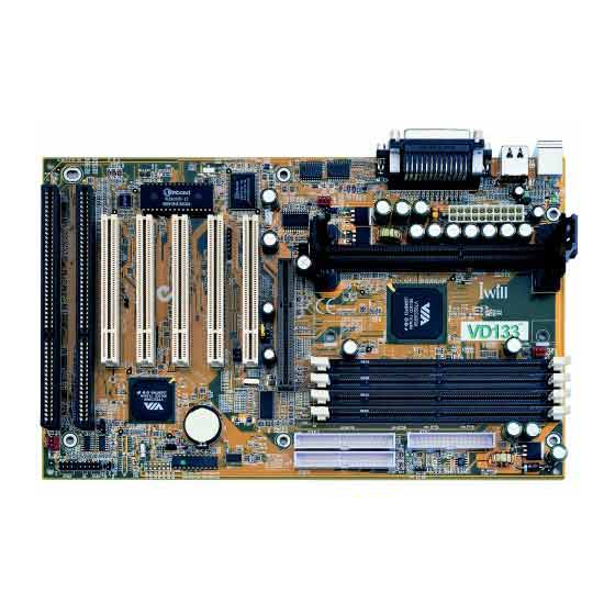
1.1 Layout........................................................................................ 3
1.2 Jumpers ..................................................................................... 4
1.3 Expansion Slots / Sockets ......................................................... 7
1.4 Connectors ................................................................................ 9
1.5 Form Factor............................................................................. 15
Overview ...................................................................... 17
Features ....................................................................... 20
3.1 Motherboard Components Placement ...................................... 20
3.2 Back Panel .............................................................................. 22
3.3 Block Diagram ........................................................................ 23
3.4 Specifications .......................................................................... 24
Hardware Setup.......................................................... 26
4.1 Before Installation ................................................................... 26
4.2 Jumper setting .......................................................................... 26
4.3 Install the Processor ................................................................ 29
4.4 Install Memory Modules ......................................................... 33
4.5 Install PCI Expansion Cards .................................................... 34
4.6 Usage of the AMR slot ............................................................ 35
VA133 series V1.6B
FB11342350000
1
Advertisement
Table of Contents

Related Manuals for IWILL VD133


Summary of Contents for IWILL VD133
-
Page 1: Table Of Contents
Table of Content Quick Installation ............3 1.1 Layout..................3 1.2 Jumpers ..................4 1.3 Expansion Slots / Sockets ............7 1.4 Connectors ................9 1.5 Form Factor................15 Overview ..............17 Features ............... 20 3.1 Motherboard Components Placement ........20 3.2 Back Panel ................ - Page 2 5.7 Power Management Setup ............64 5.8 PnP/ PCI Configurations............68 5.9 PC Health Status..............70 5.10 IWILL Smart Setting .............. 71 5.11 Load Fail-Safe Defaults ............72 5.12 Load Optimized Defaults............73 5.13 Set Supervisor / User Password Setting ........ 73 5.14 Save &...
-
Page 3: Quick Installation
Chapter 1 Quick Installation Chapter 1 Quick Installation Layout VD133 Pro Series... -
Page 4: Jumpers
Chapter 1 Quick Installation Jumpers 1.2.1 JP1 (CMOS) Clear CMOS jumper The jumper is for BIOS setting value. 1.2.2 JPA & JPB CPU FSB select jumper 1.2.3 J41A (Tsys) System temp. sensor header VD133 Pro Series... - Page 5 Chapter 1 Quick Installation 1.2.4 PCI compatibility jumper 1.2.5 JP9(Vcore+) CPU core voltage select jumper VD133 Pro Series...
-
Page 6: Expansion Slots / Sockets
Chapter 1 Quick Installation 1.2.6 VIO select jumper Expansion Slots / Sockets 1.3.1 J1(Socket 370) Processor socket VD133 Pro Series... - Page 7 Chapter 1 Quick Installation 1.3.2 J3—J5 (DM0—DM2) 168-Pin DIMM Sockets Install memory in any combination as follows: Location Support Module Type Single-Side Module Double-Side Module Single-Side Module Double-Side Module Single-Side Module Double-Side Module Total System Memory (Max1.5 GB) VD133 Pro Series...
- Page 8 Chapter 1 Quick Installation 1.3.3 J12—J16 (PCI 1—PCI 5) PCI expansion slots The connectors are Bus Master PCI Expansion Slots. 1.3.4 J11 (AGP) AGP Slot VD133 Pro Series...
-
Page 9: Connectors
Chapter 1 Quick Installation Connectors 1.4.1 J28 (IDE0) Primary ATA/66 IDE channels 1.4.2 J29 (IDE1) Secondary ATA/66 IDE channels 1.4.3 J30 (FDC) Floppy connector VD133 Pro Series... - Page 10 Chapter 1 Quick Installation 1.4.4 J37 ATX power connector 1.4.5 J39(FCPU)&J41(FSYS) fan connectors on this motherboard. The J39 (FCPU) is designed to support CPU fan; the J41 (FSYS) is for system fan used . VD133 Pro Series...
- Page 11 Chapter 1 Quick Installation 1.4.6 J43 This connector is composed of all the headers that may be connected to the front panel of the chassis. 1.4.7 J45 (IR) This connector is designed for the SIR devices. VD133 Pro Series...
- Page 12 Chapter 1 Quick Installation 1.4.8 J46 (WOL) This is the Wake-on-LAN connector. In order to wake up the system through a plug- in network card, the card must provide a high active wake signal. 1.4.9 J47(MODEM) VD133 Pro Series...
- Page 13 Chapter 1 Quick Installation 1.4.10 J48(SMBUS) VD133 Pro Series...
- Page 14 1.4.11 J34A (USB1) The motherboard provides four USB support for the commonly found USB devices now a days. The motherboard has two USB ports onboard. The extra two USB support can only functionable with the additional USB riser kit. VD133 Pro Series...
-
Page 15: Form Factor
Chapter 1 Quick Installation Form Factor VD133 Pro Series... - Page 16 Chapter 2 Overview VD133 Pro Series...
-
Page 17: Overview
[ ] Iwill SIDE-2936UW PCI Ultra Wide SCSI controller [ ] Iwill SIDE-2935LVD PCI Ultra2 SCSI controller [ ] Iwill SIDE-DU280 PCI Dual channel Ultra2 SCSI controller [ ] Iwill SIDE-DU3160 PCI Dual channel Ultra160 SCSI controller [ ] MR card... - Page 18 Notice Information furnished in this manual is believed to be accurate and reliable. However, Iwill Corporation assumes no responsibility for its use, nor for any infringements of patents or other rights of third parties which may result from its use. Iwill Corporation reserves the right to change product specifications at any time without notice.
- Page 19 Journal of the European Communities: EN 50081-1 Emissions: EN 55022 Radiated, Class B EN 55022 Conducted, Class B EN 60555-2 Power Harmonics EN 50082-1 Immunity: IEC 801-2 Electrostatic Discharge IEC 801-3 RF Radiate IEC 801-4 Fast Transient VD133 Pro Series...
-
Page 20: Features
Chapter 3 Features Chapter 3 Features Motherboard Components Placement VD133 Pro Series... - Page 21 VIA 82C686X Chipset Programmable BIOS 32bit/33MHz Bus Master PCI Slot AMR Slot(VA133 removed function) Joystick, Midi Line Out ,Line in, Microphone In Connector (VA133 removed this function) COM1Connector Parallel Connector COM2Connector USB Connectors PS/2 Mouse, PS/2 Keyboard Connector. VD133 Pro Series...
-
Page 22: Back Panel
Chapter 3 Features Block Diagram VD133 Pro Series... -
Page 23: Specifications
Support AGP 1X/2X AGP mode. Main Memory Supports three DIMM sockets Support PC66/PC100/PC133 SDRAM Support 16M/64M/256M/512M SDRAM technology Maximum memory up to 1.25GB/768MB when using 256M/64M-16M tecnology. Support 3.3V Unbuffered/Registered DIMM Support Singel-Sided/Double-sided DIMMs Support ECC memory module VD133 Pro Series... - Page 24 Supports one PS2 keyboard port Supports one SIR port Supports PS2 mouse and PS2 keyboard Supports 4 UHCI Universal Serial bus Port Expansion Slots Three DIMM sockets Five 32bit/33 MHz Bus Maser PCI Slots One AMR Slot One AGP Slot VD133 Pro Series...
- Page 25 Supports BIOS ROM Flash Control (S/W protection) Supports “AC-Loss Recovery”(Former status/OFF) Supports suspend to Disk BIOS Support 2M flash ROM Support Plug & Play Supports APM 1.2 Supports DMI 2.1 Supports ACPI 1.0 Year2000 compliance Others ATX Form Factor 30.5 x 19.4 cm VD133 Pro Series...
-
Page 26: Hardware Setup
1-2, place onto pins 2-3, and then place back onto pins 1-2 again. Then, turn on your computer, press <Del> key during boot up and enter the BIOS setup program to re-set your preferences. VD133 Pro Series... - Page 27 Chapter 4 Hardware Setup 4.2.2 JP9(Vcore+) CPU core voltage select jumper VD133 Pro Series...
- Page 28 This jumper allows you to select the voltage supplied to the DRAM, chipset, PCI and the CPU’s I/O buffer. The default voltage should be used unless processor over- clocking requires a higher voltage. s ' t f i l i t t s t i . t l VD133 Pro Series...
-
Page 29: Install The Processor
Chapter 4 Hardware Setup Install the Processor c i f a i l The motherboard is provides a ZIF Socket 370. Step1: Locate the ZIF socket and open it by first pulling the lever of socket upward. VD133 Pro Series... - Page 30 Insert the CPU into the socket. Please keep the lever right angle when inserting CPU. Step3: When inserting the CPU please note the correct orientation as shown. The notched corner should point toward the end of the lever. l l i t i f VD133 Pro Series...
- Page 31 Chapter 4 Hardware Setup Step4: Push the lever down to close the socket. Step5: Attach the heatsink onto the CPU. VD133 Pro Series...
- Page 32 Chapter 4 Haredware Setup Step6: Push the clip of heatsink downward to hock the ear of socket firmly. Step7: Finally, attach the fan cable to the CPU fan header FCPU. i t t a l i . e l VD133 Pro Series...
-
Page 33: Install Memory Modules
Total System Memory (Max1.5 GB) Step 1:Open latches of DIMM socket Step 2:Proofread the RAM module to the DIMM Socket Step 3:Insert the RAM module into the Step 4:Press the latches into the notches DIMM Socket of the RAM module VD133 Pro Series... -
Page 34: Install Pci Expansion Cards
After installing the necessary software drivers, you can enjoy the features that expansion card provided. y l l . t i i l c c i f l l i c i f c i f VD133 Pro Series... -
Page 35: Usage Of The Amr Slot
OS to access large textures outside the local graphic memory of the card. In order to take advantage of the DIME feature, some software components should be installed or upgraded within your system. VD133 Pro Series... -
Page 36: Connect Devices And Power Supply
A legacy ATA (IDE) drive can coexist with an Ultra ATA/66 drive. However, for the Ultra ATA/66 device to attain Ultra DMA 4 mode, an Ultra ATA/66 capable cable is required. VD133 Pro Series... - Page 37 This motherboard has one floppy connector to support 360K, 720K, 1.2M, 1.44M, 2. 88M, 3 Mode floppy drives and QIC-80 floppy tape drive. After connecting the single end to the board, connect the two plugs on the other end to the floppy devices. VD133 Pro Series...
- Page 38 The “Sense” signal is to be used only by a specially designed fan with rotation signal. You may use the hardware monitoring utility to monitor the Rotations per Minute (RPM) of the fan. VD133 Pro Series...
- Page 39 Chapter 4 Hardware Setup 1. The CPU will overheat if there is no airflow across the CPU heatsink. 2. Damage may occur to the CPU fan and/or motherboard if these pins are incorrectly used. VD133 Pro Series...
- Page 40 4.7.5.5 System Power LED Connector (PLED) This 3-pin connector connects to the case-mounted system power LED, which lights when the system is powered on. 4.7.5.6 Speaker Connector (SPKR) This 4-pin connector connects to the case-mounted speaker. VD133 Pro Series...
- Page 41 You may need to enable the “Wake Up by Ring/LAN” feature in the BIOS setup program. b. Your system must have a ATX power supply with at least 720mA 5VSB power. c. This motherboard only supports the LAN card with a high-active wake signal. VD133 Pro Series...
- Page 42 This connection works in conjunction with your modem card. If you intend to use a modem card (inserted into the PCI slot), please connect the cable from the modem card into the Modem header. 4.7.9 SMBUS connector (SMBUS) This connector provides the connectivity of SMBUS utilization. VD133 Pro Series...
- Page 43 Chapter 4 Hardware Setup 4.7.10 USB 1 VD133 Pro Series...
- Page 44 Many of the power supply support 110V/220V by a switch setting. Switch your power supply to the correct supply voltage (refer to the power supply’s manual). 4.7.13.6 Turn on your system in the following order: The monitor. (2). The external devices. VD133 Pro Series...
- Page 45 Shut down your operating system. 4.7.14.3 Switch off the power button. If you are using Windows 95/98, the power supply should turn off automatically after Windows shut down 4.7.14.4 Turn off all the external devices. 4.7.14.5 Turn off your monitor. VD133 Pro Series...
-
Page 46: Bios Setup
5.1.1 Upgrade BIOS The BIOS can be upgraded from a diskette with the Award Flash utility — AWDFLASH.EXE. The BIOS image file, and update utility are available from IWILL’s WEB site: www.iwill.net 5.1.2 Enter BIOS setup program Power-on the system by either pressing the Power-On button, or by using any of the power-on features provided by the motherboard. -
Page 47: Main Menu
The main menu allows you to select from several setup pages. Use the arrow keys to select among these pages and press <Enter> key to enter the sub-menu. A brief description of each highlighted selection appears at the bottom of the screen. VD133 Pro Series... -
Page 48: Standard Cmos Features
Selects the type of fixed disk. Auto (*) BIOS automatically fills in the values for the cylinders, heads and sectors fields None Any Disk Drives are attached 5.3.3.3 Capacity Auto Display your disk drive size VD133 Pro Series... - Page 49 No 3 Mode drive is connected Drive A A 3 Mode drive is connected as drive A Drive B A 3 Mode drive is connected as drive B Both Both drive A and drive B are 3 Mode drives VD133 Pro Series...
-
Page 50: Base Memory
The BIOS determines how much extended memory is present during the POST. This is the amount of memory located above 1MB in the processor’s memory address map. This field has no options. 5.3.10 Total Memory Displays the total memory available in the system VD133 Pro Series... -
Page 51: Advanced Bios Features
If you run such a program, we recommend that you first disable the Virus Warning function beforehand. Options Enabled Disabled (*) 5.4.2 CPU Internal Cache This field configures the CPU internal cache (L1 cache). Options Enabled (*) Disabled VD133 Pro Series... -
Page 52: External Cache
5.4.7 First / Secondary / Third / Other Boot Device The BIOS attempts to load the operating system from the devices in the sequence selected in these items. Options Floppy (*) LS/ZIP HDD-0 (**) SCSI CD-ROM HDD-1 HDD-2 HDD-3 RAID66) (***) (VD133 Pro only) Disable VD133 Pro Series... -
Page 53: Boot Other Device
1 MB. At first, the gate A20 was handled from a pin on the keyboard. While some keyboards still provide this support, it is more common, and much faster, for modern system chipsets to provide support for gate A20. Options Description Fast support by core logic Normal(*) Disable VD133 Pro Series... -
Page 54: Typematic Rate Setting
When enabled, this field allows you to access the memory that is over 64MB under OS/2. Options OS/2 Non-OS/2 (*) 5.4.18 Report No FDD For WIN 95 For a floppy diskless system that runs Windows 95, this field should be set to Yes. Options No (*) VD133 Pro Series... -
Page 55: Advanced Chipset Features
Such a scenario might well occur if your system had mixed speed DRAM chips installed. Longer delays might result, however this preserves the integrity of the data held in the slower memory chips. VD133 Pro Series... -
Page 56: Sdram Cycle Length
In order to improve performance, certain space in memory is reserved for ISA cards. This memory must be mapped into the memory space below 16MB. Note: This field is for experienced users only. Options 15M-16M Disabled (*) VD133 Pro Series... -
Page 57: Cpu To Pci Write Buffer
The chipset has embedded 32-bit posted writer buffer to support delayed transaction cycles. When enable, the system is compliant with PCI specificationversion 2.1 Options Enabled (*) Disabled 5.5.10 System BIOS cacheable When enable accesses to the system BIOS will be cached Option Enable(*) Disable VD133 Pro Series... -
Page 58: Video Ram Cacheable
Options Enabled Disabled (*) 5.5.15 USB Keyboard Under DOS Select Enabled if your system contains a Universal Serial Bus (USB) controller and you have a USB keyboard under DOS Options Enabled Disabled (*) VD133 Pro Series... -
Page 59: Integrated Peripherals
Use Mode 0 timing to access device Mode 1 Use Mode 1 timing to access device Mode 2 Use Mode 2 timing to access device Mode 3 Use Mode 3 timing to access device Mode 4 Use Mode 4 timing to access device VD133 Pro Series... -
Page 60: Init Display First
AGP (*) 5.6.7 AC97 Audio Removed the AC97 Audio. Still shows the item on the BIOS frame. This item allows you to decide to enable/disabled the VIA Chipset family to support AC97 Audio. Options Auto Press Enter VD133 Pro Series... - Page 61 Option Disable 200-207H(*) 5.6.8 AC97 Modem Removed the AC97 Audio. Still shows the item on the BIOS frame. This item allows you to decide to enable/disable the VIA chipset family to support AC97 Modem. Options Auto(*) Disable VD133 Pro Series...
-
Page 62: Ide Hdd Block Mode
Hi, Lo (*) / Lo, Hi / Lo, Lo / Hi, Hi 5.6.12.2 IR Duplex Mode When setting the field to either HPSIR or ASKIR, you must select the mode of receiving and transmitting signals. Options Half (*) / Full VD133 Pro Series... -
Page 63: Onboard Parallel Port
DMA channel and the EPP version need to be specified. Please check the specifications before selecting field. DMA Options Description Use DMA channel 1 3 (*) Use DMA channel 3 EPP Options Description EPP1.7 Use EPP 1.7 protocol EPP1.9 (*) Use EPP 1.9 protocol VD133 Pro Series... -
Page 64: Power Management Setup
This field specifies the timer value of Doze Mode. It is available only when the Power Management field set to User Define. Options 1 Min / 2 Min / 4 Min /6 Min / 8 Min /10 Min/ 20 Min 30 Min / 1 Hour / Disable (*) VD133 Pro Series... -
Page 65: Acpi Suspend Type
Options Description V/H SYNC+Blank Turn off the vertical and horizontal synchronization ports and write blanks to the video buffer Blank Screen Writes blanks to the video buffer only DPMS (*) Initial display power management signaling with DPMS VD133 Pro Series... -
Page 66: Modem Use Irq
When On, any activity from one of the listed system peripheral devices or IRQs wakes up the system. Options None LPT/COM (*) 5.7.9.3 HDD & FDD When On, any activity from either hard disk drive or floppy disk drive wakes up the system. Options ON (*) VD133 Pro Series... - Page 67 I/O device wants to gain the attention of the operating system, it signals this by causing an IRQ to occur. When the operating system is ready to respond to the request, it interrupts itself and performs the service. VD133 Pro Series...
-
Page 68: Pnp/ Pci Configurations
Normally, you leave this field Disabled. Select Enabled to reset Extended System Configuration Data (ESCD) when you exit Setup if you have installed a new add-on and the system reconfiguration has caused such a serious conflict that the operating system can not boot. Options Enabled Disabled (*) VD133 Pro Series... -
Page 69: Resources Controlled By
All cases except above 5.8.5 PCI 1/ On board RAID IRQ Use (On board RAIID VD133 Pro only) This field determines the IRQ setting for PCI1. PC1 and PC2 may share the same IRQ, or other options may be selected. The default setting for this field is Auto, which uses automatic-routing to determine the setting. -
Page 70: Pc Health Status
Options Auto (*) / 3 / 4 / 5 / 7 / 9 / 10 / 11 / 12 / 14 / 15 PC Health Status This page is monitoring your status of computer. On the screen displays CPU/System temperature, FAN speed, and voltages. VD133 Pro Series... -
Page 71: Iwill Smart Setting
Chapter 5 BIOS Setup 5.10 IWILL Smart Setting Over-clocking is not guaranteed. Users must have substantial knowledge of proper CPU relative to adjusting CPU speeds. Over-clocking should be done only by experienced engineers who conduct tests. 5.10.1 Auto Detect DIMM/PCI Clk When enabled, the motherboard will automatically disable the clock source for a DIMM socket, which does not have a module on it. -
Page 72: Load Fail-Safe Defaults
When you press <Enter> on this item you get a confirmation dialog box with a message similar Pressing ‘Y’ loads the BIOS default values for the most stable, minimal-performance system operations. on this item you get a confirmation dialog box with a message similar to: VD133 Pro Series... -
Page 73: Load Optimized Defaults
To disable a password, bring the cursor to this field, then press <Enter>. The computer will display the message, “Enter Password”. Press <Enter>. A message will confirm that the password is disabled. Once the password is disabled, the system will boot and you can enter setup program freely. VD133 Pro Series... -
Page 74: Save & Exit Setup
800Mhz = 100Mhz x 8 How to setup CPU frequency in IWILL Smart Setting IWILL provides a triple stepping system bus selection in VA series motherboards. It allows user to select various FSB speed ranging from 66MHz ~ 166Mhz. This section will describe how does this works. - Page 75 However, the fact is, most of the CPU in the market now comes with multiplier locked. No effect will be taken even the multiplier setting is altered in the IWILL Smart Setting. Furthermore, a higher system bus frequency (FSB) has a much better performance than a slower system bus frequency.
-
Page 76: Power Installer Cd
Power Installer CD Software Installation The attached Power Installer CD contains all the necessary drivers, utilities for IWILL’s full range of motherboards. It provides an easy way for users to install the needed drivers without going through a complicated process. The Power Installer CD is able to auto-detect and display the drivers, utilities needed for your motherboard. -
Page 77: How To Make Driver Diskette
Chapter 6 Power Installer CD 6.2.1 How to view manual This Power Installer CD includes detailed information of all IWILL manuals for every motherboard manufactured by IWILL. Please insert the IWILL Power Installer CD into the CD-ROM drive; Click the “View Manual” item, and select the product that you want to view. - Page 78 Simply click on the Anti-Virus shown on screen that be installed, then follow the prompts to complete setup. 6.2.8 How to use Hardware Monitoring Utility(Window 9X only) You may just click on the Hardware Monitor Utility shown on screen then follow the prompts to complete setup. VD133 Pro Series...
-
Page 79: Installing Operating Systems
Press <ENTER>. Microsoft ScanDisk will check your disk drives for errors. When ScanDisk finishes, press the X key. Setup will initialize. Then, Windows 98 Setup begins. Please follow the instructions that are displayed. VD133 Pro Series... - Page 80 Select “Boot Sequence” and change the default setting from A, C, SCSI to “CD-ROM, C, A” using Page Up /Page Down key. Place the Windows NT 4.0 CD-ROM in the drive. Follow all instructions to finish Windows NT installation. VD133 Pro Series...
Need help?
Do you have a question about the VD133 and is the answer not in the manual?
Questions and answers