Table of Contents
Advertisement
Quick Links
EC Declaration of Conformity
We
IWILL Corporation
No. 10, Wu Chuan 3rd Rd.,
Hsin Chuang City, Taipei,
Taiwan, R.O.C.
Declare under sole responsibility that the
VD133 motherboard
Meets the intent of Directive 89/336/ECC for Electromagnetic Compatibility. Compliance was
demonstrated to the following specifications as listed in the official Journal of the European
Communities:
EN 50081-1 Emissions:
EN 55022
EN 55022
EN 60555-2 Power Harmonics
EN 50082-1 Immunity:
IEC
IEC
IEC
Radiated, Class B
Conducted, Class B
801-2 Electrostatic Discharge
801-3 RF Radiate
801-4 Fast Transient
1
Advertisement
Table of Contents

Related Manuals for IWILL VD133


Summary of Contents for IWILL VD133
- Page 1 Hsin Chuang City, Taipei, Taiwan, R.O.C. Declare under sole responsibility that the VD133 motherboard Meets the intent of Directive 89/336/ECC for Electromagnetic Compatibility. Compliance was demonstrated to the following specifications as listed in the official Journal of the European Communities:...
-
Page 2: About This Manual
Keep this manual for future upgrades or system configuration changes. Chapter 0 Overview An overview of some special and basic features of the VD133 motherboard Chapter 1 Features The detailed features and specifications of the VD133 motherboard... -
Page 3: Table Of Contents
QUICK INSTALLATION ................15 CHAPTER 3 ....................19 HARDWARE INSTALLATION ..............19 3.1 P ............. 19 REPARATION AND NSPECTION 3.2 U VD133................19 NPACK THE 3.3 I ..............20 NSTALLATION PROCEDURE CHAPTER 4 ....................30 SYSTEM BIOS SETUP................30 4.1 I .................. - Page 4 4.8 INTEGRATED PERIPHERALS ............47 4.9 LOAD SETUP DEFAULTS ..............52 4.10 IWILL SMART SETTING..............52 4.11 SUPERVISOR PASSWORD SETTING ..........54 4.13 IDE HDD AUTODETECTION............54 4.14 SAVE & EXIT SETUP............... 54 4.15 EXIT WITHOUT SAVING..............54 CHAPTER 5 ....................55 HOW TO USE POWER INSTALLER ............
-
Page 5: Chapter 0
Keep this for your future reference. VD133 FEATURES The VD133 is the newest, most exciting motherboard in the market today. A step ahead of the competition, the VD133 provides more power, convenience, and reliability for users. The VD133 has more speed, and is great for better, fast computer graphics. - Page 6 Peripherals and Devices If you want to improve your system’s I/O performance, choose the latest IWILL SCSI controllers. The following are some IWILL SCSI controllers you may purchase and use with your VD133 motherboard: SIDE 2930C: a fast SCSI for MO, CD-R, CD-R/W, CD-ROM. This value/performance SCSI card connects up to 7 devices.
-
Page 7: Chapter 1
Chapter 1 Features 1.1 Features 1.1.1 Processor ® Supports single Pentium III/II/Celeron processors Supports 133 MHz, 100 MHz and 66 MHz bus speeds ® Supports all published Pentium III/II/ Celeron processor voltages Jumper inside selects the processor speed from 233 MHz to 500 MHz or higher 1.1.2 Core Logic VIA-VT82C693A APOLLO PRO 133 Integrated DRAM controller... -
Page 8: Main Memory
1.1.3 Main Memory 3 x 168-pin DIMM (Dual Inline Memory Module) sockets The VD133 motherboard supports the following memory features: JEDEC MO-161 compliant 168-pin DIMMs with gold-plated contacts Supports up to 1.25 GB of 3.3 V Unbuffered SDRAM, Registered DIMM, or 60-ns Extended Data Out (EDO) memory Single-sided or double-sided DIMMs (3.3 V memory module only) -
Page 9: Environment Requirements
1.1.7 Manageability Winbond W83781 System Hardware Monitor built-in. Wake on LAN header for use with add-in network interface cards (NICs) Flash Control Hardware Monitoring Wake on modem 1.1.8 Other features Award BIOS Using 2Mbit Flash ROM to provide on-board-upgrade ability without changing components Plug and Play compatible Supports Advanced Power Management (APM) Supports ACPI (Advanced Configuration Power Interface) -
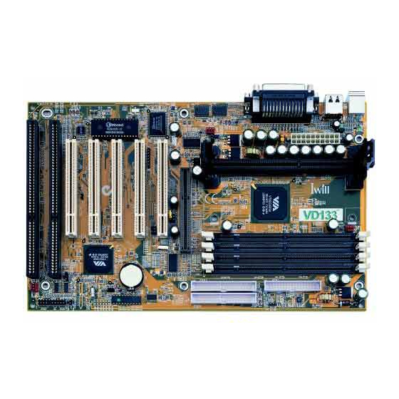
Page 10: Motherboard Components Placement
1.3 Motherboard Components Placement The following figure shows the location of the components on the VD133 motherboard. FAN2 (bottom) TEMP2 MS(top) ISAx KB_ON SLOT1 TEMP1 FAN1 PCIx DIMM0 DIMM1 DIMM2 JP42 FAN3 TEMP3 JP11 IDE0 SB-LINK IDE1 PWR-ON JP12 JP10... - Page 11 Location Symbol Description Slot 1 Processor Slot 1 connector J5 — J7 DIMM0--2 Memory Module Sockets AGP slot J12--J16 PCI1--5 PCI slots J21--J22 J21, J22 ISA slots IDE 0 Primary IDE connector IDE 1 Secondary IDE connector Floppy drive connector Serial 1 connector Serial 2 connector Parallel connector...
-
Page 12: Back Panel Connectors
1.4 Back Panel Connectors The following figure shows the location of the back panel I/O connectors, which include: PS/2-style keyboard and mouse connectors Two USB connectors Two serial port connectors One parallel port connector Mouse USB1 Parallel Keyboard USB0 Serial 1 Serial 2... -
Page 13: Form Factor
1.5 Form Factor The VD133 motherboard is designed to fit into an ATX form-factor chassis. The I/O connector and mounting locations are in compliance with the ATX specification. Please see details in the following figure: Datum (0, 0) 6.250 R E A R I / O W I N D O W I N C H A S S I S 0.800 TYP. -
Page 15: Chapter 2
Chapter 3. Note: Please review 1.3 Motherboard Components Placement graphic for reference. Warning: Users must follow these guidelines to ensure the VD133 is protected during installation. Make sure your computer is unplugged whenever working with inside components. Beware of Static electricity! Either wear anti-static wrist straps, or ensure that you touch a safely grounded object (such as a metal desk/table). - Page 16 Step 3. Setting CPU speed The CPU speed is setup using IWILL Smart Setting. This is found in the BIOS setup by pressing <Del> during the boot up process. Please refer to Chapter 4 for instructions on setting CPU speed.
- Page 17 Step 7. Connect the Speaker The 4-pin speaker header is located on pins 17--20 (identified as SPKR. Connect the cable from the SPKR header to the speaker on the front panel of your PC case. Locate the SPKR header on the motherboard: Pin 17 Pin 18 Ground...
- Page 18 ATX power connector into the Power-On button. Step 13. Install the Power Supply cord The VD133 motherboard provides a 20-pin ATX power connector. This works in conjunction with the Power-On button to provide remote On/Off function. Step 14. Install the Keyboard Connect the cable from the PS/2 keyboard connector at the back panel to the keyboard.
-
Page 19: Chapter 3
Hardware Installation 3.1 Preparation and Inspection The VD133 motherboard, like all other electronic equipment, is sensitive to static. Please take the proper precautions when handling it. If possible, ground yourself by touching a metal table or desk. Keep the board in its conductive wrapping until it is configured and ready to be installed in your system. -
Page 20: Installation Procedure
Connect processor fan: This process is executed more quickly if your CPU already has a fan attached to it. On the VD133 motherboard, there are three fan connectors, J39 for FAN1 (for the CPU), J40 for FAN2, and J41 for FAN3. - Page 21 3.3.2 Setting CPU speed The CPU speed is setup using IWILL Smart Setting. This is found in the BIOS setup by pressing <Del> during the boot up process. Please refer to Chapter 4 for instructions on setting CPU speed. When adjusting frequency, select the frequency that matches your motherboard's bus speed in order to maximize your motherboard's performance.
- Page 22 The VD133 motherboard’s main memory can run at different speeds than the FSB (Front Side Bus). For example, if your FSB runs at 133MHz, you may select a memory speed of 100MHz or 133MHz. Or, if your FSB runs at 100MHz, you may select a memory speed of 100MHz or 133MHz. Please see Chapter 4, section 4.5.3 DRAM Clock for DRAM Clock settings.
- Page 23 Supports a maximum of 127 physical devices Supports data transfer rate up to 12 Mbit/sec The VD133 motherboard has two USB ports; any USB peripheral can be connected to either port. For more than two USB devices, connect a hub to either port.
- Page 24 (secondary) fans in order to take advantage of this function. The VD133 motherboard supports two extra system fan headers: FAN2 and FAN3. Connect the power cable from the FAN2/3 header to each additional fan used within your system. These fans automatically stop when the system enters the suspend mode.
- Page 25 3.3.13.3 Power LED header (PLED) If connected, the LED will light up each time you power-on the PC. The 3-pin power LED header is located on pins 11--13 (identified as PLED). To use this function, connect the cable from the PLED to the LED located on front panel of your PC case. Locate the PLED header on the motherboard: Pin 11 Anode (+)
- Page 26 3.3.14 Clear CMOS jumper block (JP1) To reset the RTC (Real Time Clock) CMOS data, take the JP1 jumper cap off pins 1-2, place onto pins 2-3, and then place back onto pins 1-2 again. This will return the RTC to the default setting. Then, you will need to get into the BIOS setup program (See Chapter 4) select LOAD SETUP DEFAULTS, and select the original manufacturer default settings in your CMOS.
- Page 27 The VD133 is PCI Rev2.1 compliant, and has five 32-bit, 33MHz PCI expansion slots for your PCI expansion cards. You may use your 64-bit PCI host adapter on VD133, however the PCI host adapter would only run a 32-bit data transfer rate. Select any of the 5 PCI slots, and connect your PCI expansion cards into the PCI expansion slots.
- Page 28 33 MHz Warning: Each time you change the FSB frequency using the jumper setting, you must immediately re-enter BIOS setup, and enter IWILL Smart Setting (See Chapter 4). Then, immediately press <F10> key to exit, then restart your system. 3.3.23 PS/2 Power-On (J52) This is essential for the PS/2 Power-On to function properly (see below).
- Page 29 3.3.25 Adjustable Vcore (JP9) This function offers adjustable processor Vcore. When NO jumper caps are used, the motherboard automatically generates the proper Vcore voltage that requested by the CPU. Place the jumper cap over pins 1-2 to increase 5% more voltage to the processor’s Vcore. Place the jumper cap over pins 2-3 to increase 10% more voltage to the processor’s Vcore.
-
Page 30: Chapter 4
System BIOS Setup 4.1 Introduction The VD133 motherboard uses AWARD BIOS, which is stored in flash memory and can be upgraded using the appropriate software program. The setup program is for viewing and changing the BIOS setting for a computer. These settings are stored in battery-backed RAM so that it retains all the settings after the power has been turned off. -
Page 31: Main Menu
<Esc> Quit from setup program without saving changes, or Exit from current menu page and return to main menu page <PgUp> or <+> Select the previous value for a field <PgDn> or <-> Select the next value for a field <F1>... -
Page 32: Standard Cmos Setup
LOAD SETUP DEFAULTS Loads the manufacturer default setting into CMOS IWILL SMART SETTING Specifies special features SUPERVISOR PASSWORD Specifies supervisor password USER PASSWORD Specifies user password IDE HDD AUTO DETECTION Auto-detects the parameters of IDE disks SAVE & EXIT SETUP... - Page 33 4.3.3.2 Size If you select Auto, this field automatically fills in the size your hard disk and can not be modified. If you select User, you must type the correct size for your hard disk. 4.3.3.3 Cylinders If you select Auto, this field automatically fills in the number of cylinders for your hard disk and can not be modified.
-
Page 34: Base Memory
1.44M, 3.5 in. (*) A 1.44M floppy drive is connected (*Drive A default) 2.88M, 3.5 in. A 2.88M floppy drive is connected 4.3.5 Floppy 3 Mode Support 3 Mode floppy drive is a type of 3.5-inch drive used by NEC PC98 computers. It supports both 1.2M and 1.44M formats using the same drive. -
Page 35: Extended Memory
4.3.9 Extended Memory The BIOS determines how much extended memory is present during the POST. This is the amount of memory located above 1MB in the processor’s memory address map. This field has no options. 4.3.10 Other Memory This refers to the memory located in the 640K to 1024K address space. This memory can be used for different applications. -
Page 36: Boot Sequence
4.4.5 Quick Power-On Self Test When enabled, BIOS will shorten or skip some items during the Power-On Self Test (POST). Options Enabled (*) Disabled 4.4.6 Boot From LAN First This field configures the boot from the network adapter. If this feature is enabled, no matter what Boot Sequence you select (see below section 4.4.7), the system will try to boot from the network adapter first. -
Page 37: Boot Up Floppy Seek
4.4.9 Boot Up Floppy Seek When enabled, during POST the system seeks the detailed status and detects any errors in both floppy drives A and B. Options Enabled (*) Disabled 4.4.10 Boot Up NumLock Status This field determines the configuration of the numeric keypad after system boot up. If On, the keypad uses numbers keys. -
Page 38: Security Option
4.4.15 Security Option This field configures how the system security is handled. It works conjunction with SETTING SUPERVISOR / USER PASSWORD page to control the security level of the system. Options Description Setup (*) System needs a password to enter BIOS setup program System System needs a password to boot 4.4.16 PCI / VGA Palette Snoop... -
Page 39: Chipset Features Setup
4.4.21 C8000-CBFFF / CC000-CFFFF / D0000-D3FFF Shadow D4000-D7FFF / D8000-DBFFF / DC000-DFFFF Shadow When enabled, the extended ROM data located at the respective address range will be copied to system memory. Options Enabled Disabled (*) 4.5 CHIPSET FEATURES SETUP This setup page is used to specify advanced features available through the chipset. The default settings have been chosen carefully for most operating conditions. -
Page 40: Memory Hole
4.5.4 DRAM Parity / ECC Check When enabled, the BIOS will use ECC (Error Checking and Correcting) protocol to increase integrity of system data. All memory modules used in the system need to support ECC in order for this function to work properly. Options Enabled Disabled (*) -
Page 41: Onchip Usb
4.5.11 AGP-2X Mode This item allows you to enable / disable the AGP-2X (Clock 133MHz) Mode. Options Enabled (*) Disabled 4.5.12 OnChip USB This should be enabled if your system has a USB installed on the system board and you wish to use it. Even when so equipped, if you add a higher performance controller, you will need to disable this feature. -
Page 42: Video Off Method
4.6.3 Video Off After This field specifies the suspend or power-saving mode, which shuts off the video. Options Suspend (*) Doze 4.6.4 Video Off Method This field specifies the method that video subsystem used for power-saving. Options Description V/H SYNC+Blank (*) Turn off the vertical and horizontal synchronization ports and write blanks to the video buffer Blank Screen... -
Page 43: Doze Mode
4.6.8 Doze Mode This field specifies the timer value of Doze Mode. It is available only when the Power Management field set to User Define. Options 10 Sec / 20 Sec / 30 Sec / 40 Sec 1 Min / 2 Min / 4 Min / 8 Min / 12 Min / 20 Min 30 Min / 40 Min / 1 Hour / Disable (*) 4.6.9 Suspend Mode This field specifies the time the system enters power-saving mode. -
Page 44: Wake Up On Lan
4.6.13 DMA/master When On, the system can be resumed from power saving mode by any DMA / master activity signal. Options OFF (*) 4.6.14 Wake Up On LAN When enabled, the PC can power-on or “wake up” through LAN (Local Area Network). Used only when your PC is connected to a network system. -
Page 45: Pnp/ Pci Configuration
IRQ9 (IRQ2 Redir) Primary / Secondary (*) / Disabled IRQ10 (Reserved) Primary / Secondary (*) / Disabled IRQ11 (Reserved) Primary / Secondary (*) / Disabled IRQ12 (PS / 2 Mouse) Primary (*) / Secondary / Disabled IRQ13 (Coprocessor) Primary (*) / Secondary / Disabled IRQ14 (Hard Disk) Primary (*) / Secondary / Disabled IRQ15 (Reserved) -
Page 46: Cpu To Pci Write Buffer
4.7.5 CPU to PCI Write Buffer When this field is enabled, CPU data is written to a write buffer prior to being sent to the PCI bus, in order to compensate for the speed differences between the CPU and the PCI bus. When disabled, the CPU data is sent directly to the PCI bus, however, because the CPU operates at a faster speed than the PCI bus, the CPU must wait as the PCI bus receives data before beginning each write cycle. -
Page 47: Agp Master 1 Ws Read
4.7.11 AGP Master 1 WS Read When enabled, the system will “wait” one wait state (AGP clock cycle), before data is read by the AGP bus. When disabled, data is read by the AGP (Accelerated Graphics Port) bus immediately (i.e. zero or “0”... -
Page 48: Ide Prefetch Mode
4.8.3 IDE Prefetch Mode The onboard IDE drive interfaces supports IDE prefetching, for faster drive accesses. If you install a primary and/or secondary add-in IDE interface, set this field to disabled if the interface does not support prefetching. Options Enabled (*) Disabled 4.8.4 IDE HDD Block Mode When enabled, the IDE controller will use the faster block mode to access devices. -
Page 49: Kbc Input Clock
4.8.7 KBC input clock This field sets the frequency speed for the keyboard controller clock. Please ensure you know the keyboard data rate (according to the keyboard’s specifications) before selecting frequency speed. Options 6 MHz / 8 MHz (*)/ 12 MHz / 16MHz. 4.8.8 Onboard FDC Controller This field enables or disables the onboard floppy controller. -
Page 50: Init Display First
4.8.11.1 ECP Mode Use DMA When the Parallel Port Mode field is configured as ECP, it needs a DMA channel for data transfer. This field specifies the DMA channel for ECP parallel port use. DMA Options Description Use DMA channel 1 3 (*) Use DMA channel 3 4.8.11.2 EPP Mode Select... -
Page 51: Uart Mode Select
Mouse left Enables Mouse left function. You can assign a Mouse left key through the Mouse left Power-On field. “Double-clicking” the left button on your mouse will power-on your system. Mouse right Enables Mouse right function. You can assign a Mouse right key through the Mouse right Power-On field. -
Page 52: Load Setup Defaults
CPU speeds. Over-clocking should be done only by experienced engineers who conduct tests. Upon entering Iwill Smart Setting, you will notice several temperature and speed readings on the left side of the screen. The VD133 is constantly being monitored to ensure its safety. -
Page 53: Spread Spectrum
0.50% 4.10.5 BIOS-ROM Flash Protect The VD133 motherboard provides solid protection at BIOS ROM. When set to Non-Flash, it will prevent any changes to the data in BIOS. There are two cases that you may need to configure this field to Flashable: In order to update the Extended System Configuration Data (ESCD) when you install or remove any device. -
Page 54: Supervisor Password Setting
Flashable 4.11 SUPERVISOR PASSWORD SETTING This setup page is used for setting a password in order to enter BIOS. This prevents any unauthorized person from changing any part of your BIOS system configuration. Additionally, if the Security Option field is set to “Boot,” the BIOS will request a password every time your system boots. To enter a password, select “Supervisor Password Setting,”... -
Page 55: Chapter 5
Select the one that needs to be installed, then simply follow the messages displayed on the screen to complete setup. Note: IWILL Power Installer does not support a keyboard at this moment. You must use a mouse to install it. -
Page 56: How To Make Driver Diskette
During the boot-up process, you can perform “IWILL Diskette Creator,” which will automatically make the driver diskettes you need. Note: At least one CD-ROM drive and one 1.44M floppy drive are needed to use “IWILL Diskette Creator”. - Page 57 “Suspend to Disk” diskette to use for installation. Insert the Power Installer CD into your CD-ROM, select Make Driver Diskette from the menu, and carefully follow the instructions to make a driver diskette. Please see Chapter 5.2.2 in the VD133 manual to create a driver diskette without an operating system.
-
Page 58: Enter Bios Setup
Power-on the system by either pressing the Power-On button, or by using any of the power-on features provided by the VD133 motherboard. Then, press the <Del> key after the Power-On Self Test (POST), and before the scanning of IDE devices. Simply look for the message “Press DEL to enter SETUP”... - Page 59 The system will ask, “Are you Ready?” Press “y” for “yes.” Press <Enter>. Insert your Suspend to Disk diskette into your floppy disk drive. (See above). Type the following: C:\>A: Press <Enter> Create a file or partition There are two ways to store the data into HDD: Create a file or partition. You must make sure you have enough disk space before selecting either option (Please refer to System Requirements for installing Suspend to Disk above).
- Page 60 Whether you have selected file or partition options, once the Suspend to Disk utility has been set up, press any key, and you will automatically return to Windows. Then, you must restart your system in order to enable the Suspend to Disk feature. Whether you have selected file or partition options, once the Suspend to Disk utility has been set up, press any key, and you will automatically return to Windows.
-
Page 61: Installing Operating Systems
C:\>A: Press <Enter> To delete file, type the following: A:\>zvhdd /d /file (Note one space is between “zvhdd and “/d”, and one space is between “/d” and “/file”) To delete partition, type the following: A:\>zvhdd /d /partition (Note one space is between “zvhdd and “/d”, and one space is between “/d” and “/partition”) Press any key to return to Windows. - Page 62 The Microsoft Windows 98 Startup menu will appear. Place the Windows 98 CD into your CD-ROM drive. Run the batch file to install CD-ROM. A series of scans is performed, and then the MS-DOS prompt is displayed. Type the word setup next at DOS prompt (next to “D:\>”), and press <ENTER>. Setup performs a check (A message will be displayed).
-
Page 63: How To Use The Thermal Sensor
5.5 IWILL SCSI series If you want to improve I/O performance of your VD133, choose the latest IWILL SCSI controllers. The following are some IWILL SCSI controllers you may purchase, and use with your VD133 motherboard:... - Page 64 Up to 12 meters cable length for Ultra 2 devices Able to connect up to 15 devices Able to boot from any SCSI ID Able to boot from CD-ROM Please contact IWILL today for more information regarding our SCSI cards.
Need help?
Do you have a question about the VD133 and is the answer not in the manual?
Questions and answers