SCIFIT ISO1000R Service Manual
Hide thumbs
Also See for ISO1000R:
- Owner's operation manual (38 pages) ,
- User's operation manual (32 pages) ,
- Machine user manual (22 pages)

Related Manuals for SCIFIT ISO1000R


Summary of Contents for SCIFIT ISO1000R
- Page 1 ISO1000R Service Manual SALES: 800-278-3933 CUSTOMER SERVICE: 800-745-1373 Revision: August 1999...
-
Page 2: Table Of Contents
Procedure 4 – Removal and Replacement of the Brake Assembly Figures Figure 1 – Standard ISO1000R Total Assembly Figure 2 – Standard ISO 000R Main Frame Figure 3 – Bi-Directional ISO1000R Total Assembly Figure 4 – Bi-Directional ISO1000R Main Frame Figure 5 –... -
Page 3: Overview
Sections II and III contain some troubleshooting tables and maintenance procedures for the two models. Figures 1 and 2 show the standard ISO1000R while Figures 3 and 4 show the bi-directional ISO1000R. Figures 5 and 6 are universal. References are made to the figures in the troubleshooting tables and maintenance procedures. -
Page 4: Troubleshooting Tables
II. Troubleshooting Tables Note: A reference given in parenthesis, “(See Figure…)”, is intended for the servicing of a bi-directional unit. A reference without parenthesis is followed when servicing a standard unit. Table 1 – Electrical Troubleshooting Problem Possible Reasons Solutions 1.1 The machine appears to Faulty power supply If buttons on the control display... - Page 5 1.6 Unit keeps blowing Too many units are Do not daisy-chain more than 3 fuses. daisy-chained together. units together. Faulty power supply Check and replace power supply board. board as needed. See Procedure 2. 1.7 The upper display resets Ribbon cable connection Check cable connection at power after starting a program.
- Page 6 Table 2 – Mechanical Troubleshooting Problem Possible Reasons Solutions 2.1 Pedals lock up while Power supply board is Unplug power cord. If rails move, operating. faulty. replace power supply board. Brake is bad. If pedals do not move with power cord unplugged, replace brake.
-
Page 7: Maintenance Procedures
Plug into power source and turn on. Procedure 3 – Checking and b. The message “SCIFIT FOR Adjusting the Speed Sensor SCIENTIFIC SOLUTIONS” 1. Turn machine on and press start. should be scrolling across... -
Page 8: Procedure 4 - Removal And Replacement Of The Brake Assembly
Remove the brake from the should read 4-5 VDC. machine and set aside to return 9. If there is no voltage, replace the to SCIFIT (request a UPS call tag power supply board. If 4-5 volts by phone). are present, replace the speed 10. - Page 9 The 16. Slip the V-belt over the plastic display will be scrolling the pulley while slowly turning the message, “SCIFIT…” Slowly brake downward to install and rotate the crank arm assembly center the belt on the pulley.
-
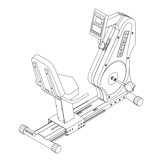
Page 10: Figures
IV. Figures Figure 1 – Standard ISO1000R Total Assembly... - Page 11 Figure 2 – Standard ISO1000R Main Frame...
-
Page 12: Figure 3 – Bi-Directional Iso1000R Total Assembly
Figure 3 – Bi-Directional ISO1000R Total Assembly... -
Page 13: Figure 4 – Bi-Directional Iso1000R Main Frame
Figure 4 – Bi-Directional ISO1000R Main Frame... -
Page 14: Figure 5 – Electrical Board With Fuse Holder
Figure 5 – Electrical Board with Fuse Holder... -
Page 15: Figure 6 – Iso1000R Wiring Diagram
Figure 6 – ISO1000R Wiring Diagram... -
Page 16: Iso1000R Parts List Standard
V. ISO1000R Parts List Standard ISO1000R Item Description Part No. Qty. overlay/switch panel 65112 Display board 65110S standoffs, 1", 6-32 P1051 heart rate pickup/cable, assy 65160 Console 65202 Bracket, mounting, pickup, heart-rate A1124 screws, 6-32x.250, p.h., cap screw, pltd. screws, 8-32 x 3/8 f. h. pltd. - Page 17 3/32 x 3/4" brkt., pivot, rod, lock A1147 handlebar, seat, iso1000r, weldment A1144 screw, 1/4-20x1.25, black, b.h., socket cap lockwasher, 1/4, black frame, seat, Iso1000r C1113 seat pad (back) 71101 seat pad (bottom) 71100 knob, ball, 7/16-20, 1.375 dia.
-
Page 18: Bi-Directional
1/4 P1056 bolts, 1/4-20 x 5/8 pltd. P1054 lockwashers, 5/16 P1059 bolts, 5/16 - 18 x 5/8 pltd. P1057 decal, Scifit P1100 washer, cover, plastic, black screw, 10-32x.5, black, b.h., socket cap P1062 cover, right P1036 decal, plate, scuff... - Page 19 1/4 x 1" brkt., pos., adj., lever A1115 pin, carter, 3/32 x 3/4" brkt., pivot, rod, lock A1147 handlebar, seat, iso1000r, weldment A1144 screw, 1/4-20x1.25, black, b.h., socket cap lockwasher, 1/4, black frame, seat, Iso1000r C1113 seat pad (back)
- Page 20 screws, 8-32 x 1/2, pan head, pltd. bolt, 3/8-24 x 2 1/2 hex, pltd. bracket, wheel, right A1016 wheel, front P1063 grommet, hole, 1" dia., P1060 bracket, wheel, left A1015 100 cover, pedal, right A1041 101 hub, sprocket, press-fit, 16T, centered A1154 102 shaft, jack A1137...
Need help?
Do you have a question about the ISO1000R and is the answer not in the manual?
Questions and answers