Table of Contents
Advertisement
Quick Links
Download this manual
See also:
Installation Manual
Advertisement
Table of Contents

Related Manuals for Bematech SB9015F


Summary of Contents for Bematech SB9015F
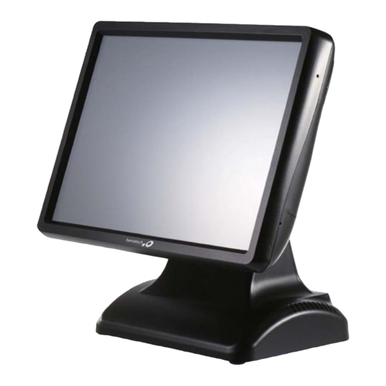
- Page 1 SB9015F All-in-one Touch POS Terminal (i3 Processor) USER MANUAL...
-
Page 2: Table Of Contents
Table of Contents Introduction ..................2 Safety Information ..................2 Electromagnetic compatibility statement ..........3 2 Overview .................... 4 Appearances ....................4 Rear panel I/O connectors ................5 Rear View ......................6 Control Panel ....................7 3 Hardware Installation ............... 8 Cable Routing.................... -
Page 3: Introduction
1 Introduction Thank you for purchasing the SB9015F(i3) all-in-one touch POS terminal, Bematech is committed to continuously improve product quality and provide better after-sales service. In order to take full advantage of our devices, we strongly recommend that you take the time to read this manual before diving into software solution. -
Page 4: Electromagnetic Compatibility Statement
Do not use harsh chemicals or strong cleaning solvents to clean the monitor screen. Wipe it clean with a soft terry cloth applied with a mild solution Do not share the same power outlet with high-power electrical appliances; keep distance from high level magnetic interference. -
Page 5: Overview
2 Overview 2.1 Appearances... -
Page 6: Rear Panel I/O Connectors
2.2 Rear panel I/O connectors At the rear panel of the SB9015F is a row of external I/O device connectors detailed as follows: DC in HDD slot DC out (for 2nd LCD) Line out Cash drawer port COM5 USB port x 4... -
Page 7: Rear View
2.3 Rear View VESA holes MSR module compartment Speakers VESA routing plate Control panel Display module compartment (for Customer display or 2nd LCD) -
Page 8: Control Panel
2.4 Control Panel Brightness – Press the “Brightness –” button to decrease brightness. The setting will be saved 6 seconds after releasing the button. Brightness + Press the “Brightness +” button to increase brightness. The setting will be saved 6 seconds after releasing the button. -
Page 9: Hardware Installation
3 Hardware Installation 3.1 Cable Routing 3.2 Installing MSR... -
Page 10: Installing Customer Display
3.3 Installing Customer Display 3.4 Installing Second LCD... -
Page 11: Replacing System Core
3.5 Replacing System Core 3.6 Replacing Hard Disk Drive... -
Page 12: Setup And Driver Installation
4 Setup and Driver Installation 4.1 Cash Drawer Port Pin-out Description Sense input 2 Drive output 1 Sense input 1 +24V/+12V Drive output 2 Ground Note: The Y cable used to support two cash drawers on the single RJ-11 socket is same as that for Epson printers. -
Page 13: Serial Ports Configurations
4.2 Serial Ports Configurations Connectors Function Pin 9 Power Support COM1 External, RS232 RI/+5V/+12V select by jumper COM2 External, RS232 RI/+5V/+12V select by jumper COM3 Customer Display +5V only COM4 External, RS232 (RJ45) RI/+5V/+12V select by jumper COM5 Touch controller +5V only COM6 External, RS232... - Page 14 JP6 - CN7 Cash Drawer Power Selection +24V Default=+24V +12V JP7 - CN1 USB Power Selection +5VSB Default=+5VSB JP8 - CN4 USB Power Selection +5VSB Default=+5VSB JP9 - COM4 RS232 pin 9 function select Default=RI +12V JP10 - COM6 RS232 pin 9 function select Default=RI +12V JP11 - COM2 RS232 pin 9 function select...
- Page 15 JP13 - PS/2 Keyboard Power Selection +5VSB Default=+5VSB Note: Do not plug in or unplug any connector except USB devices when the power is on. The current loading for all COM ports should not exceed DC 5V/3A and DC 12V/2A.
-
Page 16: Motherboard Bios Settings
4.4 Motherboard BIOS settings The POS terminal has a BIOS (Basic Input Output System) chip on the motherboard. Every time you start the terminals, the system will first run the BIOS self-test routine to check the main components of the system to ensure it is working properly. -
Page 17: Main Menu
Main Menu System Time and Date Setting: Under <Main>, select < System Date > or <System Time> to change the system date and time. Main Advanced Chipset Boot Security Save & Exit BIOS INFORMATION Build date and time 05/14/2013 19:02:18 BIOS Version →... - Page 18 AHCI Setting: Under < Advanced >, select <SATA Mode Selection>. Main Advanced Chipset Boot Security Save & Exit Enable or disable SATA SATA Controllers(s) Enabled Device SATA Mode Selection → ← Select Screen Serial ATA Port 0 Empty ↑↓ Select Item Software Preserve Unknown Enter: Select...
- Page 19 Com and Parallel Port IRQ Setting: Under < Advanced >, select < F81866 Super IO Configuration >. Main Advanced Chipset Boot Security Save & Exit Super IO Configuration → ← Select Screen ↑↓ Select Item F81866 Super IO Chip F81866 Enter: Select ►...
- Page 20 Security Tab Set the Supervisor or User password first to use the security features. Main Advanced Chipset Boot Security Save & Exit Password Description If ONLY the Administrator’s password is set, then this only limit access to Setup and is only asked for when entering Setup.
-
Page 21: Touch Screen Driver Installation
4.5 Touch screen driver installation Step 1: Navigate to the installer directory to find the setup.exe file. Double-click on “setup.exe” to start installation. Step 2: When installation starts, click [Next] to proceed to the next step. Step 3: Installation in progress... - Page 22 Step 4: Uncheck “Install PS/2 interface driver” and click [Next] to continue installation. Step 5: Uncheck “install RS232 interface driver” and click [Next] to continue installation.
- Page 23 Step 6: Select option “NONE”, click [Next] to continue installation. Step 7: When installing USB touch, please connect the USB controller and USB cable...
- Page 24 Step 8: If there are additional touch monitors connected, please check “Support multi- monitor system”. Step 9: Select the destination location to install the touch driver. The default path is “C: \ Program Files \ eGalaxtouch”. Click [Next] to continue installation.
- Page 25 Step 10: Select the Program Folder to install the utility. The default is “eGalaxtouch”. Click [Next] to continue installation. Step 11: Check the option to create a desktop shortcut icon.
- Page 26 After install the driver successfully, identify the USB controller is installed as shown below. Touch function settings...
- Page 27 Touch calibration Touch device line test...
-
Page 29: Troubleshooting
5 Troubleshooting Terminal does not boot If the terminal cannot boot after repeated pressing of the power switch when connect to the power, the terminal power light remains off, the fan does not operate, and the BIOS beeping is not heard, it might be power supply problems. (a) Check the power adapter is plugged in correctly to the power outlet. - Page 30 (e) If the above steps do not resolve this problem, reinstall the operating system. 3) The touch screen does not respond (a) Remove the touch driver and then install it again. (b) Execute the “eGalaxTouch utility and check if the interface port is working. 4) When touching the screen, cursor always returns to a fixed position.
- Page 31 8) The cursor in the touch screen can only move in a small area or touch positions are inaccurate. (a) This situation usually occurs first time after installing the driver. Please run the touch screen calibration program. We also recommend you to do this after changing monitor resolution.
-
Page 32: Specifications
6 Specifications MODEL SB9015F 15” i3 All-in-one Touch POS Terminal Main Board Intel i3-2310E Processor dual core 2.1GHz System Chipset HM65 Memory 2 slots, DDR3 1066/1333, up to 4GB Storage SATA 2.5 inch Hard Disk Drive, 320GB or higher Display LCD panel 15”... - Page 33 SB9015F All-in-one Touch POS terminal...
Need help?
Do you have a question about the SB9015F and is the answer not in the manual?
Questions and answers