Table of Contents
Advertisement
Advertisement
Table of Contents

Related Manuals for Bematech SB1015


Summary of Contents for Bematech SB1015
- Page 1 SB1015 All-in-one Touch POS Terminal USER MANUAL...
-
Page 2: Table Of Contents
Table of Contents Introduction ..................2 Safety Information ..................2 Electromagnetic compatibility statement ..........3 2 Overview ....................4 Features ......................4 Appearances ....................4 Outline Dimensions ..................4 Rear panel I/O connectors ................5 3 Setup and Driver Installation ..............6 Motherboard Connectors ................ -
Page 3: Introduction
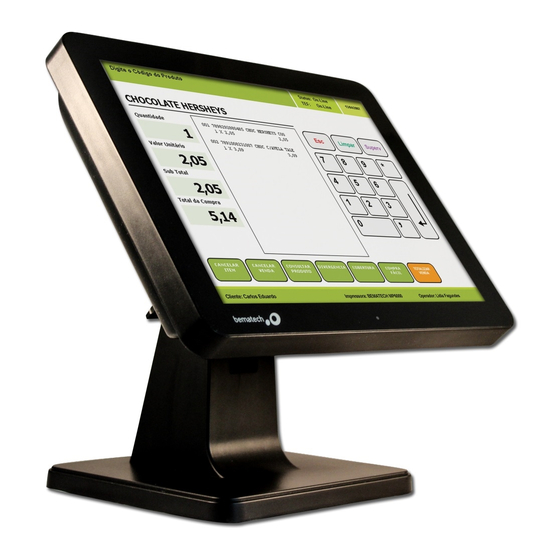
1 Introduction Thank you for purchasing the SB1015 all-in-one touch POS terminal. The SB1015 offers highly enhanced features, with easy connection to various optional devices for optimal performance. This easy-to-use POS terminal is designed to help you enhance your business flexibility and offer superior customer experience. -
Page 4: Electromagnetic Compatibility Statement
This product is in conformity with the protection requirements of EU Council Directive 89/336/EEC on the approximation of the laws of the Member States relating to electromagnetic compatibility. Bematech / Logic Controls cannot accept responsibility for any failure to satisfy the protection requirements resulting from a non-recommended modification of the product. -
Page 5: Overview
2 Overview 2.1 Features True-flat no-bezel 15" touch monitor with LED backlight display Fanless design High performance Intel quad core celeron processor J1900 Support DDR3L SO-DIMM 1066/1333 MHz up to 8GB Stable and robust mechanical design ... -
Page 6: Rear Panel I/O Connectors
2.4 Rear panel I/O connectors At the rear panel of the SB1015 is a row of external I/O device connectors detailed as follows: POWER VGA Port Line-OUT SWITCH USB 2.0 Port USB 3.0 Port COM2 Port RJ-45 LAN Port USB 2.0 Ports USB 2.0 Ports... -
Page 7: Setup And Driver Installation
3 Setup and Driver Installation 3.1 Motherboard Connectors ATX12V Power Connector HDMI Port Header DC12V Power-in Connector Intel CPU USB 2.0 Port Over USB 3.0 Port DDR3L SODIMM Slot VGA Port Header VGA Port PS2 KB/MS Header Parallel Port Header SATA Hard Disk Power-Out Connector CPUFAN1 Header... -
Page 8: Motherboard Headers
3.2 Motherboard Headers Header Name Description FP_AUDIO1 Front Panel Audio Header 9-pin Block SPEAK_CON1 Left Speaker Header 2-pin Block SPEAK_CON2 Right Speaker Header 2-pin Block SPDIF HDMI_SPDIF Header 2-pin Block COM2/3/4/5/6 Serial Port Header X 5 9-pin Block TX-RXCOM2 RS422/RS485 Header 4-pin Block JW_FP Front Panel Header(PWR LED/ HD LED/Power... - Page 9 (2) SPEAK_CON1 (2-pin)/ SPEAK_CON 2 (2-pin): Speaker Headers Pin1 Pin1 SPEAK_CON1 SPEAK_CON2 Header Header (3) SPDIF (2-pin): HDMI_SPDIF Out Header Pin1 (4) COM2/3/4/5/6 (9-Pin): Serial Port Headers Pin1 (5) TX-RXCOM2 (4-Pin): RS422/485 Header Pin 1 *Notice: User needs to go to BIOS to set ‘Transmission Mode Select’ as [RS422/RS485] for COM2 as well (refer to Page 34).
- Page 10 (7) GPIO (10-pin): GPIO Header GPIO_37 GPIO_36 GPIO_34 GPIO_35 GPIO_32 GPIO_33 GPIO_31 GPIO_30 Pin 1 (8) F_USB1 (9-pin): USB 2.0 Port Header +DATA +DATA -DATA -DATA Pin 1 (9) PS2KBMS (6-pin): PS/2 Keyboard & Mouse Header Pin1 (11) HDMI (20-pin): HDMI Header Pin 1 Pin 2 HDMI Port Header...
- Page 11 (12) CPUFAN1 (4-pin)/SYSFAN1 (3-pin): FAN Headers CPUFAN1 Pin1 Pin1 +12V Fan Power SYSFAN1 Fan Speed (13) VGA1 (12-pin): VGA Header Pin No. Definition VCC5(Reserved) VGA_VSYNC VGA_HSYNC GND_RED RED_VGA GND_GRN GRN_VGA Pin 1 GND_BLUE BLUE_VGA DDC_DATA DDC_CLK (14) JP2 (2-pin): LVDS Panel Brightness Adjustment Header Pin1...
- Page 12 (15) INVERTER (6-Pin): LVDS1 Inverter Header Pin No. Definition BKLT_PWR1 BKLT_PWR2 BKLT_EN Pin 1 BKLT_PWM GND1 GND2 INVERTER (16) LVDS (30-Pin): 24-bit dual channel LVDS Header Pin 2 Pin 1 LVDS Header Pin NO. Pin Define Pin NO. Pin Define Pin 1 LVDS_VCC Pin 2...
- Page 13 3.4 Motherboard Jumpers JBAT ME_RTC JCOMP1 JCOMP2 *JCOM2 Jumper Name Description JBAT CMOS RAM Clear Function Setting 2-pin Block ME_RTC Clear ME RTC Function Setting 2-pin Block INVERTER VCC 3.3V/5V/12V Select 4-pin Block LVDS VCC 3.3V/5V/12V Select 4-pin Block JCOMP1 COM1 Header Pin9 Function Select 6-Pin Block JCOMP2...
- Page 14 (1) JBAT (2-pin): Clear CMOS Setting 1-2 Open: Normal; 1-2 Closed:Clear CMOS (2) ME_RTC (2-pin): Clear ME_RTC Function Setting 1-2 Open: Normal; 1-2 Closed: Clear ME_RTC. (3) JP3 (4-pin): INVERTER Back Light VCC 3.3V/5V /12V Select 2-4 Closed: 3-4 Closed: 6-4 Closed: Inverter Backlight Inverter Backlight...
-
Page 15: Motherboard Bios Settings
3.5 Motherboard BIOS settings The POS terminal has a BIOS (Basic Input Output System) program located on a Flash Memory on the motherboard. This program is a bridge between motherboard and operating system. When you start the computer, the BIOS program will gain control. -
Page 16: Getting Help
3.5.3 Function Keys Press (left, right) to select screen; Press (up, down) to choose, in the main menu, the option you want to confirm or to modify. Press <Enter> to select. Press <+>/<–> keys when you want to modify the BIOS parameters for the active option. - Page 17 OS Selection The optional settings: [Windows 8.X]; [Android]; [Windows 7]. * Note: User need to go to this item to select the OS mode before installing corresponding OS driver, otherwise problems will occur when installing the driver. ACPI Settings Press [Enter] to make settings for the following sub-item: Enable Hibernation ACPI Sleep State...
- Page 18 Adjacent Cache Line Prefetch Intel Virtualization Technology Power Technology EIST Turbo Mode P-STATE Coordination CPU C6 report CPU C7 report Package C State Limit PPM Configuration Press [Enter] to make settings for PPM Configuration: EIST CPU C Status Report Max CPU C-state ...
- Page 19 Primary IGFX Boot Display LVDS Support LVDS Panel Type South Bridge Mini PCIE Onboard PCIE Lan Device Onboard Lan BootROM XHCI Mode USB 2.0 (EHCI) Support Audio Controller High Precision Timer 3.5.9 Security Menu Security menu allow users to change administrator password and user password settings.
-
Page 20: Touch Screen Driver Installation
3.6 Touch screen driver installation For resistive touch version of SB1015, follow the driver installation and calibration steps below. For PCAP touch version, no driver installation and calibration is required. 3.6.1 Navigate to the installer directory to find the setup.exe file. Double-click on “setup.exe”... - Page 21 3.6.4 Uncheck “Install PS/2 interface driver” and click [Next] to continue installation. 3.6.5 Uncheck “install RS232 interface driver” and click [Next] to continue installation. 3.6.6 Select option “NONE”, click [Next] to continue installation.
- Page 22 3.6.7 If there are additional touch monitors connected, please check “Support multi- monitor system”. 3.6.8 Select the destination location to install the touch driver. The default path is “C:\Program Files\eGalaxtouch”. Click [Next] to continue installation. 3.6.9 Select the Program Folder to install the utility. The default is “eGalaxtouch”. Click [Next] to continue installation.
- Page 23 3.6.10 Check the option to create a desktop shortcut icon. Click [Next] to continue. After install the driver successfully, identify the USB controller is installed as shown below. 3.6.11 Click on "Settings" tab to change the touch function settings as needed.
- Page 24 3.6.12 Perform touch calibration if necessary and use Draw Test to check touch accuracy after calibration.
-
Page 25: Hardware Installation
4 Hardware Installation 4.1 Magnetic Script Reader (MSR) Installation * 1. Remove the MSR mount cover from the monitor. 2. Insert MSR module. Make sure reader has been properly connect to the monitor USB port then use the 2 screws to fix the MSR. * Optional peripheral... -
Page 26: Lcd Rear Display Installation
4.2 LCD Rear Display installation * 1. Use USB cable to connect the second display and install VESA bracket set to the LCD display with M4 screws (x4). 2. Remove the display mount cover from monitor. 3. Mount the LCD display assembly to the touch monitor and secure with screws. Plug USB cable into monitor USB port. -
Page 27: Sata Hard Disk Installation
4.3 SATA Hard Disk Installation 1. Remove the HDD mount cover from the back of monitor. 2. Install HDD rubber to both side of SATA HDD. Plug SATA cable and power cable into SATA HDD connector. 3. Insert SATA HDD assembly to the monitor and install HDD mount cover. Secure cover with the coin slot screw. -
Page 28: Troubleshooting
5 Troubleshooting 1) Terminal does not boot If the terminal cannot boot after repeated pressing of the power switch when connect to the power, the terminal power light remains off, the fan does not operate, and the BIOS beeping is not heard, it might be power supply problems. (a) Check the power adapter is plugged in correctly to the power outlet. - Page 29 (a) Remove the touch driver and then install it again. (b) Execute the “eGalaxTouch utility and check if the interface port is working. 4) When touching the screen, cursor always returns to a fixed position. (a) Check if there is anything pressing on the touch screen. (b) Other high power or high frequency equipment may affect the screen or controller.
-
Page 30: Specifications
6 Specifications MAIN BOARD Intel Celeron J1900 quad-core 2.0GHz IO Chipset Fintek F71869 Memory DDR3L 1333 SODIMM slot, up to 8GB Ethernet LAN Realtek RTL8111G PCI Express Gigabit LAN Audio ALC887 Audio CODEC, HD Audio CODEC Storage SATA 2.5 inch Hard Disk Drive/SSD, mSATA SSD DISPLAY LCD panel 15"... - Page 31 SB1015 All-in-one Touch POS terminal...
Need help?
Do you have a question about the SB1015 and is the answer not in the manual?
Questions and answers