Table of Contents
Advertisement
Advertisement
Table of Contents

Related Manuals for STONEX R2W PLUS 500


Summary of Contents for STONEX R2W PLUS 500
- Page 2 R2W PLUS Dear Customer: Congratulations! We, STONEX are proud to present you with an R2W PLUS instrument. Your total station is a rugged and reliable instrument whose performance and design are not surpassed. To fully appreciate and protect your investment, we suggest that you take the necessary time to read and fully understand this manual.
- Page 3 Stored data responsibility STONEX should not be held liability for the lost data because of wrong operation. The noise from the instrument When the instrument is working, it is normal if you hear the noise from instrument motor,...
- Page 4 ●Do not put the battery in the fire or high temperature condition. Explosion, damage could result. ●If use the battery which is not specified by STONEX, there is a danger of fire, electric shock or burn. ●If use the power cable which is not specified by STONEX, there is a danger of fire.
-
Page 5: Exceptions From Responsibility
R2W PLUS ! CAUTION ●If touch the instrument with wet hand, there is danger of electric shock. ●Stand or seat on the carrying case, or turn over the carrying case arbitrarily, the instrument maybe damaged. ●Be careful of the tripod tiptoe when setup or move it. ●Drop the instrument or the carrying case, or use defective belt, agraffe or hinge, instrument damage could result. - Page 6 According to above standards, R2W PLUS Series is class Ⅲ A/3R laser products. When the prism or reflective sheet is selected in Config mode as target, the output is equivalent to the safer class 1. Once the instrument is damaged, do not disassemble it. You’d better contact STONEX or local dealer. Labels Follow the safety instructions on the labels as well as in this manual to ensure safe use .
-
Page 7: Table Of Contents
R2W PLUS CONTENT 1. Nomenclature and Functions ................... 1 1.1 Nomenclature ......................1 1.2 Keyboard ....................... 3 1.3 Comprehensive Understanding ................4 1.3.1 Basic Measurement ..................4 1.3.2 Standard Measurement ................5 1.3.3 Instrument Setup..................5 1.3.4 About ......................6 1.3.5 Third-party software ................... - Page 8 R2W PLUS 4.3.1 Horizontal angle(right angle) and vertical angle measurements ....22 4.3.2 Horizontal angle switch between right and left ........23 4.3.3 Setting horizontal angle with the “L.Angle” key ........24 4.3.4 Setting horizontal angle with the “S.Angle” key ........25 4.3.5 Setting “vertical angle and percent grade”...
- Page 9 R2W PLUS Appendix I: Atmospheric correction formula and chart(Just for reference) ...... 81 Appendix II: Correction for refraction and earth curvature ..........83 Appendix III: Assembling and disassembling for three-jaw tribrach ........ 84...
-
Page 10: Nomenclature And Functions
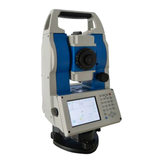
R2W PLUS 1. Nomenclature and Functions 1.1 Nomenclature Handle Handle screw Optical sight Eyepiece Instrument height mark Vertical clamp screw Vertical motion screw Battery Tribrach USB port... - Page 11 R2W PLUS Objective Horizontal motion clamp Horizontal tangent screw Keypad Touch screen...
-
Page 12: Keyboard
R2W PLUS 1.2 Keyboard R2W PLUS series is equipped with two color touch screens and alphanumeric keypad, operation by both touching screen and pressing keyboard is possible. Do not touch the screen with ball-pen, pencil or other sharp thing to avoid damage on instrument. -
Page 13: Comprehensive Understanding
R2W PLUS 1.3 Comprehensive Understanding Function introduction Display After initiating the instrument the screen will go to present “Welcome Interface” which is shown right. STONEX AIOSurvey consists of several functions, that is, “BSC Measure “STD (Basic Measurement)”, Measure “Engineering (Standard Measurement)”,... -
Page 14: Standard Measurement
R2W PLUS Measurement, Plane Offset Measurement, and Column Offset Measurement. Besides, basic measurement also appropriate checking performance functionality and index of angle measurement and distance measurement for total station. 1.3.2 Standard Measurement Function introduction Display Standard measurement function is used to resolve and calculate applied measurements during conventional surveying. -
Page 15: About
Display Third-party software provides professional surveying and cartography function. It’s main interface of “FieldGenius” in the right figure. In fact, the application program interface of STONEX instrument system supports more third-party softwares. 1.3.6 Convenient panel Function introduction Display Click 【★】 key to enter into convenient panel.Electronic bubble function on this panel... -
Page 16: Shortcut Key
R2W PLUS 1.4 Shortcut key 1)Some shortcut keys are applied in R2W PLUS series. Key combination Description ⊙ Power on/off ★ Enter into setting mode directly/Turn on the electronic bubble α Shift among number, smaller letter and capital letter FUNC+BS+⊙ Enter this combination at the same time before starting up to backup all settings FUNC+CTRL+⊙... -
Page 17: Touch Screen Calibration
R2W PLUS 1.5 Touch screen calibration When you operate on the screen, if your device isn’t responding to your taps, you may need to recalibrate your screen. In any picture, press the combination key “CTRL+TAB” so as to enter into touch screen calibration. The calibration process is shown in the figure below. 1) Carefully press and briefly hold stylus on the center of the target. -
Page 18: Battery
R2W PLUS 1.6 Battery 1.6.1 Battery Power indicator At any screen interface, press【★】key to open fast setting menu. Select Battery, battery level will be seen following Battery Level. NOTE: 1. The battery’s working time will be affected by many factors, such as ambient temperature, recharging time, recharging and discharging times. -
Page 19: Recharge Battery
R2W PLUS 2. Press the top of the battery until you hear a Click. 1.6.3 Recharge battery 1) Connect the charger connector to the battery. 2) Plug the charger on 100V/240V power supply. The red lamp becomes lighting, which indicates recharging. If interval-time is longer, the connector isn’t fixed well. 3) That the green lamp flashes means recharging is complete. -
Page 20: Usb Connection
R2W PLUS 1.7 USB connection ● The file in the instrument could be read through ActiveSync software by USB cable. ● External memory stick could be used by USB Host connector. The file in the external memory stick could be read in the instrument interface. 1)Open the cover of USB which behind the display panel;... -
Page 21: Guide Light(Optional)
R2W PLUS 1.8 Guide light (Optional) Guide light is optional for R2W PLUS Series total station. It is mainly used to stake out. The Surveyor could adjust the position of prism and station through the guide light color. It will be faster to set the prism. The guide light could be seen within 100M. -
Page 22: Preparation Before Measurement
R2W PLUS 2. Preparation before Measurement 2.1 Setting up the instrument (1) Set up the tripod first: extend the extension legs to suitable lengths and tighten the screws on the legs. Make sure the legs are spaced at equal intervals and the head is approximately level. Set the tripod so that the head is positioned over the surveying point. - Page 23 R2W PLUS (2) Accurate Levelling-Up with plate level Screw B Screw A 1. Loosen the horizontal motion clamp, and turn the instrument till the plate level is parallel to a line shaped Plate level with screws A and B. Adjust the screws A and B to make the bubble in the center of the level.
-
Page 24: Centering
【XYOFF】don’t compensate X axis and Y axis 【A.OFF】don’t compensate X axis and Y axis,and turn off the popup function of electronic bubble. In STONEX FieldGenius software, the Level display is always shown as left figure. 2.3 Centering 2.3.1 Centering with Optical Plummet (Optional) -
Page 25: Centering With Laser Plummet
R2W PLUS Cross mark Plummet Center Optical plummet Turn the focusing ring of the optical plummet to focus the ground mark point. Then adjust three foot-screws to center the bubble of the circular level. If the plate level is not leveling-up, you can loosen the center screw of the tripod, and move the instrument to center the bubble of the plate level. -
Page 26: Instrument Settings
◄ or ► keys, different setting screen can be shifted. NOTE: This password is open for all users, current configuration settings can be checked here, but not be adjusted. If you want to adjust these settings, please contact local distributer or STONEX company. -
Page 27: Setting The Measure Condition
R2W PLUS 3.1.1 Setting the measure condition Operation: 1. The distance measurement mode will be: Fine, Coarse, Repeat Fine, Average Fine, Tracking. 2. Tilt correction mode will be: HV, V, NO, Always off. 3. Collimator correction mode will be: Yes or 4. -
Page 28: Setting Parameters Of Communication Ports
R2W PLUS 3.1.3 Setting parameters of communication ports As left shows, click “Other Setup”, you can activate Bluetooth (BT) and guidelight (GL), and set parameters of “Bluetooth Port” and “Phy Port”. 3.1.4 Instrument parameters review Click “Data Monitor” used for reviewing the setting parameters. -
Page 29: Illumination Settings
R2W PLUS 3.2 Illumination settings Press the【★ 】 button and click “Target” and “Battery” keys in order to go on with illumination settings including “Cross Light”, “Guide Light”, and“Laser Point”. Cross Light: Click this item to turn on the reticle illumination, and move the slipping button to adjust reticle illumination. -
Page 30: Basic Measurement Program
R2W PLUS 4. Basic measurement program 4.1 Run the program “Basic Measurement” Current parameters Function keys Measurement mode 4.2 Basic measurement screen introduction The function keys display in the lower left corner of screen, and they vary from one measurement mode to another. There are some function keys under every measurement mode being listed in the following table. -
Page 31: Angle Measurement Mode
R2W PLUS Line Start traverse surveying Offset Start offset measurement (ANG.Offset, DIST Offset, PLANE Offset, CYL.Offset) function Coor Order Set displayed coordinate order as NEZ or ENZ Save Coor Save coordinate of instrument station or not Ang.Unit Set Ang.Unit as DMS, GON, MIL Dist Unit Set Dist Unit as m, UsFeet, IntFeet Stop... -
Page 32: Horizontal Angle Switch Between Right And Left
R2W PLUS ③ Collimate the second first Collimate B target B, and the horizontal angle and vertical angle will display on the screen of instrument. 4.3.2 Horizontal angle switch between right and left Make sure the operation is under angle measurement mode. Operation steps Keys Display... -
Page 33: Setting Horizontal Angle With The "L.angle" Key
R2W PLUS 4.3.3 Setting horizontal angle with the “L.Angle” key Make sure the operation is under angle measurement mode. Operation steps Keys Display ① Turn horizontal circle unit in the needed direction with horizontal clamp and tangent part. ② Click “L.Angle” key, and activate the function of 【L.Angle】... -
Page 34: Setting Horizontal Angle With The "S.angle" Key
R2W PLUS 4.3.4 Setting horizontal angle with the “S.Angle” key Make sure the operation is under angle measurement mode. Operation steps Keys Display ① Collimate target point used for Orientation. ② Click “S.Angle” key, and a 【S.Angle】 dialog box will be ejected, as is showed in the right figure. -
Page 35: Setting "Vertical Angle And Percent Grade" Mode With The "V/%" Key
R2W PLUS 4.3.5 Setting “vertical angle and percent grade” mode with the “V/%” key Make sure the operation is under angle measurement mode. Operation steps Keys Display ① Make sure the operation is under angle measurement mode. ② Click “V/%” key. 【V/%】... -
Page 36: Carrying Out Angle Retesting With The "Repeat" Key
R2W PLUS 4.3.6 Carrying out angle retesting with the “Repeat” key This program is applied for adding up angle retesting values, displaying the sum and the average of all observed values, and meantime recording the number of observations. Operation steps Keys Display ①Click “Repeat”... - Page 37 R2W PLUS ②Collimate the first target Collimate A ③Click “S.Zero” key, and 【S.Zero】 set horizontal angle as zero. ④Collimate second target B using horizontal Collimate B clamp and tangent part.
- Page 38 R2W PLUS ⑤Click “L.Angle” key. 【L.Angle】 ⑥Collimate the first target A again using horizontal Collimate clamp and tangent part. again ⑦Click “Unlock” key. 【Unlock】 ⑧Collimate second target again using horizontal clamp Collimate tangent part. again “L.Angle” key. ⑨Click then screen 【L.Angle】...
-
Page 39: Distance Measurement Mode
R2W PLUS 4.4 Distance measurement mode 4.4.1 Distance measurement and measuring mode setting Operation steps Keys Display ① Collimate the center of Collimate prism. ② Click “M.Dist” key to 【M.Dist】 enter distance measurement mode, and then the system will carry out measurement based on previous setting mode. -
Page 40: Fine/Tracking Distance Measurement
R2W PLUS ④ Display result measurement. ※ 1~※ 2 ※ 1 Click “mode” key if you wanna change measurement mode, as step ③ shows. ※ 2 Click “M.Ang” key to return to angle measurement mode. 4.4.2 Fine/Tracking distance measurement When you preset the measuring times, the instrument will carry out distance measurement and display the average distance according to the setting times. - Page 41 R2W PLUS ② Click “N Fine” key with 【N Fine】 stylus, and then input the input number needed number observations in the upper observations right column of screen. ③ Click “Enter” key, collimate center prism, and then the system will carry out measurement based on previous setting.
-
Page 42: Accurate Measurement And Track Mode
R2W PLUS 4.4.3 Accurate Measurement and Track mode Accurate Measurement mode: It’s a normal measurement mode. Track mode: Track mode takes less time than accurate measurement. It is mainly applied for setting-out survey and useful for tracking moving target. Operation steps Keys Display ①... -
Page 43: Exchange Of Distance Units
R2W PLUS 4.4.4 Exchange of distance units Change distance unit on the screen of distance observation. Operation steps Keys Display ① Click “m/ft” key. 【m/ft】 ② Changed distance unit will display in the upper right corner. ※1 ※1 Distance unit will be exchanged among meter, American feet and international feet every time you click “m/ft”... - Page 44 R2W PLUS Operation steps Keys Display ① Click “Setout” key under 【Setout】 distance measurement mode. ② Select distance measurement mode (SD, HD, VD) to be set out, input required data and then click “Enter” key. ※1 ③ Start setting out. ※1 First of all, a prompt that reminds you to input SD to be set out is displayed in the popup dialog box.
-
Page 45: Remote Elevation Measurement(Rem
R2W PLUS 4.4.6 Remote Elevation Measurement (REM) The Remote Elevation program calculates the vertical distance (VD) of a remote object relative to ground. When using a prism height, the remote elevation measurement will start from the prism (reference point). If no prism height is used, the remote elevation will start from any reference point in which the vertical angle is established. - Page 46 R2W PLUS ②Select “with PH” button 【with PH】 with stylus. ③Input the prism height Input prism following PH. height ④Collimate the center P of Collimate prism. prism ⑤Click “M.Dist” key to 【M.Dist】 start measuring. ⑥Horizontal distance between instrument and prism will be shown.
- Page 47 R2W PLUS ⑦Click “Continue” key, and 【Continue】 position of prism is locked, that means reference point is confirmed. ⑧Collimate target K and 【 Collimate click “Continue”, vertical K】 distance (VD) will shown. ※1) ※1)Click “Exit” key to finish REM. 2) Without prism height input...
- Page 48 R2W PLUS Operation steps Keys Display ①Select “None PH” button 【None PH】 with stylus. ②Collimate ground Collimate point. prism ③Click “M.Dist” key to start observing. ④Horizontal 【M.Dist】 distance between instrument prism will be shown. ⑤Click “Continue” key, and 【Continue】 position of ground point G is locked that means reference point is confirmed.
- Page 49 R2W PLUS ⑥Click “Continue” key. 【Continue】 ⑦ Collimate remote target Collimate K.Vertical distance(VD) will target be shown. ※ 1) ※ 1) Click “Exit” to finish REM.
-
Page 50: Missing Line Measurement (Mlm)
R2W PLUS 4.4.7 Missing Line Measurement (MLM) The Missing Line Measurement program calculates the horizontal distance (dHD), slope distance (dSD) and elevation (dVD) between two target prisms. The instrument can accomplish this in two ways: 1. MLM Method (A-B, A-C): Measurement is A-B, A-C, A-D, ..2. - Page 51 R2W PLUS Operation steps Keys Display ① Under distance measurement, click “MLM” 【MLM】 key to activate Missing Line Measurement. ② Select method (A-B, A-C) with stylus. ③ Collimate prism A,click “M.Dist” key. Horizontal 【M.Dist】 distance between instrument and prism A will be shown.
- Page 52 R2W PLUS ④ Collimate prism B, click 【M.Dist】 “M.Dist” key. ⑤ Click “Continue” key,then horizontal distance (dHD), elevation difference (dVD) 【Continue】 and slope distance (dSD) between prism A and prism B will display. ※ 1) ⑥ In order to calculate the horizontal distance between points A and C, collimate prism C, and click “M.Dist”...
-
Page 53: Line-Height Measurement
R2W PLUS ⑦ Click “Continue” key,then dHD, 【Continue】 between prism A and prism C will be shown. ※ 1)Click “Exit” key to return to main menu. ●Procedure of MLM Method (A-B, B-C) is completely same as Method (A-B, A-C) Method. 4.4.8 Line-height Measurement This function is applied for measuring and determining a height of line (like electric wire) above ground which is hard to reach. - Page 54 R2W PLUS Operation steps Keys Display ① Under distance measurement mode, click “LHM” key to activate 【LHM】 line-height measurement program. ② Select “With PH” button With PH with stylus. ③ Click “Setup” key to input instrument height (IH) and 【Setup】 prism height (PH).
- Page 55 R2W PLUS ④ Collimate prism A, click “Measure” key, and distance 【Measure】 measurement begins. After that click “Continue” key. ⑤ Collimate prism B, click “Measure” key, and distance 【Measure】 measurement begins. ⑥ After measurement click 【Continue】 “Continue” key.
- Page 56 R2W PLUS ⑦ Collimate point L on overhead line. The screen displays measuring data of collimating L. Vertical distance between A and L. Horizontal distance between instrument and L. Off: Horizontal distance between A and L. ⑧ Click “Continue” which is used for measuring height between overhead...
- Page 57 R2W PLUS ⑩ Click “Continue” again, and then height of 【Continue】 overhead line(LH) horizontal distance(Off) will ※ 1)~※ 3) display. ※ 1) Click “X” key to end measurement. ※ 2) Click “VH” key to return to operation step⑦.
-
Page 58: Coordinate Measurement Mode
R2W PLUS 4.5 Coordinate Measurement Mode 4.5.1 Setting coordinate of occupied point After input coordinate of occupied point (instrument location), unknown point coordinate will be measured and displayed with this program. Operation steps Keys Display ① Click “M.Coor” key to 【M.Coor】... -
Page 59: Setting Backsight Point
R2W PLUS ③ Input coordinate occupied point from N to Z. ④ Finishing data entry,click “Enter” key and return to 【Enter】 coordinate measurement interface. 4.5.2 Setting backsight point Operation steps Keys Display ① Click “S.BS” key to set 【S.BS】 backsight point. - Page 60 R2W PLUS ② Input coordinate 【Enter】 backsight point and click “Enter” key. ③ A dialog box is ejected as figure shows. ④ Collimate backsight point, click “Yes” key. And then system will define 【Yes】 backsight azimuth angle which displays in the upper left corner of coordinate measurement screen.
-
Page 61: Setting Instrument Height And Prism Height
R2W PLUS 4.5.3 Setting instrument height and prism height Coordinate measurement must be based on instrument height and prism height, thus coordinate of unknown point can be calculated easily and directly. Operation steps Keys Display ① Click “Setup” key. 【Setup】 ②... -
Page 62: Operation Of Coordinate Measurement
R2W PLUS 4.5.4 Operation of coordinate measurement With coordinate of occupied point, backsight azimuth angle, Instrument height and prism height set up,you can directly calculate coordinate of unknown point. Operation steps Keys Display ① Set coordinate occupied point instrument height/prism height. -
Page 63: Traverse Surveying
R2W PLUS ④ Click “M.Coor” key to 【M.Coor】 finish operation. ※ 4) ※ 1)If don’t input coordinate of occupied point, previous coordinate of occupied point is set as default. If don’t input instrument height and prism height, the previous is set as default too. - Page 64 R2W PLUS Set coordinate of occupied point p0 and azimuth angle from point P0 to known point Operation steps Keys Display ① Click “Line” key. 【Line】 ② Click “Save” key with 【Save】 stylus. ③ Click “Setup” key to reset instrument height and prism 【Setup】...
- Page 65 R2W PLUS ④ Collimate prism in target point P1 where instrument 【Measure】 will transferred. Meantime click “Measure” key. ⑤ Click “Continue” key and coordinate Point 【Continue】 displays in the lower left corner of screen. ⑥ Click “Save” key. Coordinate of P1 can be ascertained and it will return 【Save】...
- Page 66 R2W PLUS ⑦ After instrument established in P1,enter into traverse surveying coordinate measurement and select “Call” button with stylus. ※ 1) ⑧ Collimate last occupied point P0. Click “Setup” key, then coordinate of P1 and azimuth angle from P1 to P0 will be ascertained.
-
Page 67: Offset Measurement Mode
R2W PLUS 4.5.6 Offset Measurement Mode There are four kinds of Offset Measurement Modes: Angle Offset Measurement Distance Offset Measurement Plane Offset Measurement Column Offset Measurement 1) Angle Offset Measurement This program is used to measure the point where it’s difficult to set prism. Place the prism at the same horizontal distance from the instrument as that of point A0 to measure. - Page 68 R2W PLUS Operation steps Keys Display ① Click “Offset” key. 【Offset】 ② Click “ANG.Offset” key in ejecting dialog box. ③ Select “Free VA”(or “Lock VA”) with stylus to to start angle offset measurement.(User makes a choice on the basis of own demand) ④...
- Page 69 R2W PLUS ⑤ Collimate target A0 with horizontal clamp and tangent Collimate A0 part. ⑤ Click “Continue” key.Then slope distance,horizontal distance and elevation 【Continue】 difference from instrument to A0 and coordinate of A0 will be shown. ※ 1),※ 2) ※ 1) Click “Setup” key to set instrument height and prism height. ※2)Click “Exit”...
- Page 70 R2W PLUS ●When measuring coordinate of ground point A1, set instrument height and prism height. ●When measuring coordinate of point A0, set instrument height only (Prism height is set as 0). ●Refer to “4.5.1” to set coordinate of occupied point. Operation steps Keys Display...
- Page 71 R2W PLUS ④ Click “Continue” key,and result displays with the 【Continue】 correction of offset distance. ※ 1),※ 2) ※ 1) Click “Setup” key to set instrument height and prism height. ※ 2) Click “Exit” key to finish Distance offset measurement. 3) Column Offset Measurement It is possible to measure circumscription point (P1) of column directly, the distance to the center of column (P0), coordinate and direction angle can be calculated by measured...
- Page 72 R2W PLUS ① 【 CYL.Offse Click “CYL.Offset” key. t】 ② Collimate the center(P1) 【Measure】 of column surface, and then click “Measure” key. ③ Collimate left point(P2) of 【Continue】 column surface, and then click “Continue” key.
- Page 73 R2W PLUS ④ Collimate right point(P3) of column surface. ② Click “Continue ” key, and relational values between 【Continue】 instrument and the center of column (P0) calculated and shown. ※ 1),※ 2) ※ 1) Click “Setup” key to set instrument height and prism height. ※...
- Page 74 R2W PLUS ● Refer to “4.5.1” to set coordinate of occupied point. Operation steps Keys Display ① 【PLANE Click “PLANE Offset” key. Offset】 ② Collimate prism P1, and 【Measure】 click “Measure” key.
- Page 75 R2W PLUS ③ Collimate prism P2, and 【Measure】 click “Measure” key. ④ Collimate prism P3, and 【Measure】 click “Measure” key. ⑤ Click “Continue” key to calculate relational values 【Continue】 between collimation axis and plane. ※ 1) ※ 1)Click “Setup” key to set instrument height and prism height. ●If the three observing points can’t determine a plane, the system will display error message.
-
Page 76: About
R2W PLUS 4.6 About Operation: 1. Click “about” icon on desktop. 2. Press “Exit” to return to the basic measurement. -
Page 77: Check And Adjustment
4. Compare length of the instrument’s testing line again with a certain standard testing line . 5. If the difference is over 5 mm after the preceding operations, it is necessary to reset the instrument constant . 2) Adjustment About instrument constant setting, you must contact STONEX distributor to do that. -
Page 78: Plate Level And Circular Level
R2W PLUS 5.2 Plate Level and Circular Level 5.2.1 Plate Level 1) Check 1. Mount the instrument on a stable device (as tripod, adjusting device ), and fix it. 2. Level the instrument until the plate level is parallel to a line linking leveling foot screws A and B, then adjust the two screws to center the air bubble. -
Page 79: The Optical Sight
R2W PLUS 5.3 The Optical Sight 1) Check 1. Mount the instrument on a tripod and fix it. 2. Set a cross mark target which apart from the instrument about 50m. 3. Take the telescope sight the cross mark. 4. Observe the optical sight collimator whether collimating the cross mark, if collimate the mark, adjustment is not necessary;... -
Page 80: Laser Plummet
R2W PLUS NOTE: 1. When adjust the screws of plummet reticle, firstly loosen the screw on the moving direction of reticle, secondly tighten another screw by the same mount, clockwise turning is for tightening, and anticlockwise turning is for loosening, the turning mount for tightening or loosening should be same. -
Page 81: Vertical Cross-Hair On Telescope
R2W PLUS 5.5 Vertical Cross-hair on Telescope 1) Check (1) Set the instrument up the tripod and carefully level it; (2) Set a point A front the instrument 50m apart; (3) Collimate the point A and adjust the vertical tangent screw; If the point appears to move continuously on the hair, adjustment is not required. -
Page 82: Horizontal Collimation Error C
R2W PLUS 5.6 Horizontal Collimation Error C If the telescope’s sight line isn’t perpendicular to the horizontal axis, the collimation error will appear. The assembling, transportation and operation will cause this error. If the collimation error isn’t over the permitted range, with the program the instrument can correct this collimation error. -
Page 83: Vertical Index Error
R2W PLUS reticle. Reticle Adjusting: 1. Rotate the instrument in face right position, turning horizontal tangent screw until Hr′ = Hr+C. 2. Loosen the shield of telescope’s reticle. 3. Adjusting two screws at left and at right until the vertical hairs of telescope’s reticle coincides with the cross-hairs of collimator or target. - Page 84 R2W PLUS about ±10°. Read the face left angle Vl and face right angle Vr. (3) Calculate the index error according to the formula below: i = ( Vl+Vr-360°)/2 (4)If I<10”, no adjustment is necessary, or you have to adjust it . 2) Adjustment by program: Set-up the instrument on tripod or adjustment platform, and leveling accurately.
-
Page 85: Edm Optical Axis And The Telescope Sighting Axis Error
R2W PLUS 5.8 EDM Optical Axis and the Telescope Sighting Axis Error It is necessary to check this error after the adjustment of telescope reticle error. 1)Checking (1) Install the instrument at the tripod or a stable device and level it accurately, then power on the instrument. -
Page 86: Specifications
R2W PLUS 6. Specifications R2W PLUS Series Telescope Length 156mm Image Erect Magnification 30× ɸ Objective aperture 45mm Field of view 1°30’ Minimum focus 1.0m Angle measurement Reading system Absolute encoder Circle diameter 79mm Angle unit 360°(dms/d)/400gon/6400mil, selectable 1” / 0.0002gon/0.005mil, selectable Display resolution Detecting mode Double... - Page 87 R2W PLUS Reflectorless typ: 1.5-5sec, max.20sec ℃/℉, selectable Temperature unit Pressure unit hPa/mmHg/inchHg, selectable Temperature input range -30℃ to +60℃ (1℃ steps) Pressure input range 510hPa to 1066hPa(1hPa setps) Prism constant condition -99.9mm to +99.9mm Refraction and earth curvature correction OFF/0.14/0.2, selectable Reflecting prism constant correction -99.9mm to +99.9mm...
-
Page 88: Application Programs
R2W PLUS ℃) Approx. 4 hours Charging time (at +20 Application programs Data collection/Stake out/Resection/REM/MLM/Point to line AREA/Z coordinate/OFFset/3D Road/Traverse adjustment Tape measurement/section/axis positioning measurement Others ARM9 Core Memory 2GB internal memory Guide Light System Factory optional Sensors Built-in temperature and pressure sensors Keyboard Alphanumerical illuminated key board,both sides -20°~+50℃... -
Page 89: Standard Components
R2W PLUS 7. Standard components ● Carrying case 1 each ● Instrument 1 each ● Battery 2 each ● Charger 1 each ● Tools bag 1 each ● Adjusting pin 2 each ● Cleaning cloth 1 each ● Cleaning brush 1 each ●... -
Page 90: Appendix I: Atmospheric Correction Formula And Chart(Just For Reference)
R2W PLUS Appendix I: Atmospheric correction formula and chart(Just for reference) Factory setting: temperature: 20℃, pressure:1013hpa, 0ppm temperature: 20℃, pressure:1013hpa, 0ppm The correction: Kpt=274.417-0.2905*p/(1+0.0036*t) Kpt=278.960-0.2902*p/(1+0.0036*t) Where: p--Pressure value (hPa) t--Temperature value (℃) Kpt--Atmospheric correction (ppm) Example: t=20℃, p=1013hpa, L0=1000m. Then: Kpt=0ppm Kpt=4ppm L=L 0 (1+Kpt)=1000×(1+0×10 -6 )=1000.000m... - Page 91 R2W PLUS...
-
Page 92: Appendix Ii: Correction For Refraction And Earth Curvature
R2W PLUS Appendix II: Correction for refraction and earth curvature Considering the correction of refraction and earth curvature for distance measurement, the formula for slope distance, horizontal distance and vertical distance applied in the instrument are as followings: The conversion formula for horizontal and vertical distance is as follows when correction for refraction and earth curvature is not applied: VD=SD ∣... -
Page 93: Appendix Iii: Assembling And Disassembling For Three-Jaw Tribrach
R2W PLUS Appendix III: Assembling and disassembling for three-jaw tribrach It is convenient to assemble or disassemble the instrument from tribrach by loosen or tighten the tribrach clamp. Disassemble (1) Rotate the tribrach clamp anticlockwise until the lever is loosen. (2) One hand hold up the tribrach, another hand hold the carry handle of the instrument and lift out the instrument from the tribrach. - Page 94 R2W PLUS NOTE: These designs, figures and specifications are subject to change without notice. We shall not be held liable for damages resulting from errors in this instruction manual.
- Page 95 STONEX sales ® document or advice that may be provided to Customer by any STONEX representative in connection with Customer’s purchase of the Product. No change to the conditions of this Limited Warranty is valid unless it is made in written form and signed by an ®...
- Page 96 . Acceptance of returned merchandise ® is final only after inspection by STONEX Europe. ® Above terms and (policy shall apply as for hardware.) Dealers needs to follow STONEX Europe repair/service procedure (see appendix 4) to achieve a better and prompt service...
- Page 97 R2W PLUS result. Firmware/Software warranty. Stonex Europe doesn’t warrant that operation of Firmware/Software on any instruments will be uninterrupted or error-free, or that functions contained in Firmware/Software will operate to meet your requirements. Stonex will forward the Software/Firmware Fix to the dealer or customer.
- Page 98 (2) If dealer wants to repair an instrument under warranty period on their site: 1) If dealers (don’t) have the part in stock they have to send an official order to ® ® STONEX Europe and pay for it and then so STONEX Europe will send the new...
- Page 99 Europe shall verify it and if everything is ok the cost of the part shall be refund ( refund will be done only ® after check of the failure part and final approval of STONEX Europe). ® (3) If the instrument needs to be sent back to STONEX Europe for repair/replacement, ®...
Need help?
Do you have a question about the R2W PLUS 500 and is the answer not in the manual?
Questions and answers
How can I change the language of FieldGenius part?