Table of Contents
Advertisement
Quick Links
Download this manual
See also:
Manual
M
M
R
M
M
Manual Documentation Number: PES1A/PESV1A-0712m
B&B Electronics Mfg Co Inc – 707 Dayton Rd - PO Box 1040 - Ottawa IL 61350 - Ph 815-433-5100 - Fax 815-433-5104 – www.bb-elec.com
B&B Electronics Ltd – Westlink Commercial Park – Oranmore, Galway, Ireland – Ph +353 91-792444 – Fax +353 91-792445 – www.bb-europe.com
i
n
i
P
O
E
i
n
i
P
O
E
S
-
2
3
2
R
S
-
2
3
2
o
d
e
l
s
:
P
o
d
e
l
s
:
P
E
t
h
e
r
n
E
t
h
e
r
n
C
o
n
v
e
r
t
C
o
n
v
e
r
t
E
S
1
A
,
P
E
S
E
S
1
A
,
P
E
S
e
t
t
o
e
t
t
o
e
r
s
e
r
s
V
1
A
V
1
A
pn# 6868-rev002
Advertisement
Table of Contents

Subscribe to Our Youtube Channel
Related Manuals for B&B Electronics PES1A


Summary of Contents for B&B Electronics PES1A
- Page 1 Manual Documentation Number: PES1A/PESV1A-0712m pn# 6868-rev002 B&B Electronics Mfg Co Inc – 707 Dayton Rd - PO Box 1040 - Ottawa IL 61350 - Ph 815-433-5100 - Fax 815-433-5104 – www.bb-elec.com B&B Electronics Ltd – Westlink Commercial Park – Oranmore, Galway, Ireland – Ph +353 91-792444 – Fax +353 91-792445 – www.bb-europe.com...
- Page 2 Manual Documentation Number: PES1A/PESV1A-0712m B&B Electronics Mfg Co Inc – 707 Dayton Rd - PO Box 1040 - Ottawa IL 61350 - Ph 815-433-5100 - Fax 815-433-5104 – www.bb-elec.com B&B Electronics Ltd – Westlink Commercial Park – Oranmore, Galway, Ireland – Ph +353 91-792444 – Fax +353 91-792445 – www.bb-europe.com...
- Page 3 Technical Support e-mail: support@bb-europe.com © B&B Electronics – November 2005 Manual Documentation Number: PES1A/PESV1A-0712m pn# 6868-rev002 B&B Electronics Mfg Co Inc – 707 Dayton Rd - PO Box 1040 - Ottawa IL 61350 - Ph 815-433-5100 - Fax 815-433-5104 – www.bb-elec.com...
- Page 5 Manual Documentation Number: PES1A/PESV1A-0712m B&B Electronics Mfg Co Inc – 707 Dayton Rd - PO Box 1040 - Ottawa IL 61350 - Ph 815-433-5100 - Fax 815-433-5104 – www.bb-elec.com...
-
Page 7: Table Of Contents
Power over Ethernet (PoE) ................... 8 Configuration Connections ................... 9 CHAPTER 3: GETTING STARTED ..............11 Check the contents of your PES1A/PESV1A package. It should contain… 11 Set up the Hardware ................... 11 Power it Up ....................11 Get the IP Address ..................11 Login ...................... - Page 8 LARMS AND OTIFICATION Alarm Notification Settings ................. 24 Alarm Conditions ....................24 Alarm Destinations ..................... 25 CHAPTER 6: MANAGING THE PES1A/PESV1A ..........27 ....................27 YSTEM ETTINGS Device Identity Settings ..................27 Simple Network Management Protocol (SNMP) Settings ........27 ................
- Page 9 APPENDIX E: NETWORK CONNECTIONS ............. 47 APPENDIX F: POWER OVER ETHERNET (POE) ........... 49 Manual Documentation Number: PES1A/PESV1A-0712m B&B Electronics Mfg Co Inc – 707 Dayton Rd - PO Box 1040 - Ottawa IL 61350 - Ph 815-433-5100 - Fax 815-433-5104 – www.bb-elec.com...
- Page 10 Manual Documentation Number: PES1A/PESV1A-0712m B&B Electronics Mfg Co Inc – 707 Dayton Rd - PO Box 1040 - Ottawa IL 61350 - Ph 815-433-5100 - Fax 815-433-5104 – www.bb-elec.com B&B Electronics Ltd – Westlink Commercial Park – Oranmore, Galway, Ireland – Ph +353 91-792444 – Fax +353 91-792445 – www.bb-europe.com...
-
Page 11: Chapter 1: Introduction
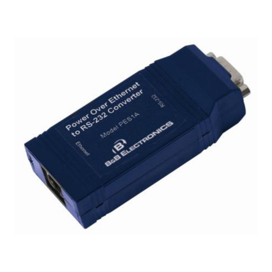
Introduction PES1A and PESV1A Mini PoE (Power over Ethernet) Ethernet to RS- 232 Converters provide simple and cost-effective solutions for connecting RS-232 devices to Ethernet networks. PES1A and PESV1A converters make it easy to connect serial printers, copiers, building automation, retail, point of sale, warehousing and banking equipment directly into Ethernet networks. -
Page 12: Communication Modes
Direct IP Mode allows applications using TCP/IP or UDP/IP socket programs to communicate with the asynchronous serial ports on the serial server. In this mode the PES1A/PESV1A is configured as a TCP or UDP server. The socket program running on the PC establishes a communication connection. -
Page 13: Paired Mode
PES1A/PESV1A and communication occurs over the network. The PES1A/PESV1A emulates modem responses to and from the serial device. In Console Management Mode the PES1A/PESV1A can be configured for connection to the management port typically found on network devices such as routers, switches and servers. - Page 14 Introduction Manual Documentation Number: PES1A/PESV1A-0712m B&B Electronics Mfg Co Inc – 707 Dayton Rd - PO Box 1040 - Ottawa IL 61350 - Ph 815-433-5100 - Fax 815-433-5104 – www.bb-elec.com B&B Electronics Ltd – Westlink Commercial Park – Oranmore, Galway, Ireland – Ph +353 91-792444 – Fax +353 91-792445 – www.bb-europe.com...
-
Page 15: Chapter 2: Hardware Overview
Hardware Overview Package Checklist PES1A/PESV1A PoE Ethernet to RS-232 Converters are shipped with the following items included: The PES1A or PESV1A module A printed version of this user manual A printed version of the PES1A/PESV1A Quick Start Guide ... -
Page 16: Indicators, Switches And Connectors
LED Indicators on the PES1A Reset Switch The Reset switch is a recessed switch located on the RJ-45 end of the PES1A and on the side of the PESV1A. The Reset switch provides two functions: Press and release within 10 seconds... -
Page 17: Ethernet Port Connector
The Ethernet Port connector is a standard RJ-45 receptacle that allows the serial server to be connected to an Ethernet network. It also carries Power over Ethernet (PoE) based on the IEEE 802.3af standard. On the PES1A/ PESV1A two indicator LEDs are built into the RJ-45 connector. Serial Port Connector... -
Page 18: Connecting The Hardware
Hardware Overview Connecting the Hardware Typically, the PES1A/PESV1A is connected to a network via a hub, switch or router using standard CAT-5 cable. Power must be supplied to the converter via the CAT-5 cable using Power over Ethernet. Configuration is... -
Page 19: Configuration Connections
Power Source* Serial Cable Serial Device PES1A PESV1A * Must be w ithin 100 ft of the PES1A/PESV1A Figure 7. Connection using Midspan Power Source Configuration Connections Your PES1A/PESV1A converter typically is configured over the network connection using standard browser software. It also could be connected directly to a PC network adapter. - Page 20 Hardware Overview Manual Documentation Number: PES1A/PESV1A-0712m B&B Electronics Mfg Co Inc – 707 Dayton Rd - PO Box 1040 - Ottawa IL 61350 - Ph 815-433-5100 - Fax 815-433-5104 – www.bb-elec.com B&B Electronics Ltd – Westlink Commercial Park – Oranmore, Galway, Ireland – Ph +353 91-792444 – Fax +353 91-792445 – www.bb-europe.com...
-
Page 21: Chapter 3: Getting Started
Connect your PC to the network Connect the PES1A/PESV1A serial port to your serial device (Use a serial cable if it is DCE, null modem cable if it is DTE.) Connect the PES1A/PESV1A Ethernet connector to a PoE-enabled network switch or hub (CAT-5 cable) 3. -
Page 22: Configure The Pes1A/Pesv1A
Start the RealPort software wizard (located on the included CD) Select Add a New Device Select your PES1A/PESV1A from the list Select an unused COM port number Follow the wizard to set up a virtual COM port 8. -
Page 23: Chapter 4: Configuring The Ip Address
Configuring the IP Address Before you can begin the configuration of your PES1A/PESV1A you must know its IP address to access it with a web browser. Once you have access to the Configuration and Management Interface via a web browser you can reset the IP address using static IP addressing, if necessary. - Page 24 Configuring the IP Address If you need to change the IP address of the PES1A/PESV1A, you can accomplish this using the discovery software, or you can open the Web Configuration and Management Interface and do it there. (See Configuring Network Settings later in the next chapter.) 1.
-
Page 25: Chapter 5: Using The Web Configuration And Management Interface
Using the Web Configuration and Management Interface The PES1A/PESV1A Ethernet to RS-232 Converter can be configured using the Configuration and Management Interface via a standard web browser such as Internet Explorer or Firefox. Logging In 1. Before you can begin configuring your PES1A/PESV1A Converter, you must login to the Configuration and Management Interface. -
Page 26: Using Tutorial And Help
Using the Web Configuration and Management Interface Using Tutorial and Help You can access the PES1A Tutorial by clicking Tutorial on the Configuration and Management homepage. Clicking Help on any page of the Configuration and Management Interface opens topics specific to that page. -
Page 27: Ip Settings
The PES1A/PESV1A‟s default setting is Obtain an IP address automatically using DHCP, or dynamic IP addressing. When the PES1A/PESV1A is first connected it will try to obtain an IP address automatically. If it fails, it will assign an IP address to itself using the Automatic Private IP Addressing (APIPA) protocol. -
Page 28: Advanced Network Settings
Profile column may indicate <Unassigned>.) To access detailed settings for the PES1A/PESV1A serial port, click Port 1. The Serial Port Configuration page that appears includes three sections with hyperlinked menu bars. -
Page 29: Console Management
RealPort Select RealPort to implement the use of virtual COM ports. This allows you to map a COM port on a PC to the serial port on your PES1A/PESV1A. Using RealPort software (included with the PES1A/PESV1A) you create a virtual COM port on the PC. When your application sends data to this port, RealPort redirects the data across the network to the PES1A/PESV1A. -
Page 30: Tcp Sockets
PES1A/PESV1A serial port. (This is also referred to as reverse telnet.) Network devices initiating connections must be configured with the IP address of the PES1A/PESV1A and the TCP port number associated with its serial port. After selecting TCP Sockets, click Apply to return to the Serial Port Configuration page. -
Page 31: Udp Sockets
When using UDP Sockets your converter can be configured as a UDP server or UDP client. UDP Server Settings If your PES1A/PESV1A is configured as a UDP server, other network devices can initiate a UDP connection with the serial device connected to the PES1A/PESV1A serial port. Network... - Page 32 Using the Web Configuration and Management Interface Figure 15. UDP Server Settings UDP Client Settings If your PES1A/PESV1A is configured as a UDP client you can automatically distribute serial data from you PES1A/PESV1A to many devices at the same time. This is sometimes referred to as Data Distribution or UDP Multicast.
-
Page 33: Basic Serial Settings
Terminal Select Terminal to communicate with the PES1A/PESV1A via its serial port using a terminal program and a command line interface. For more information on this option and the command line interface contact B&B Electronics Technical Support. -
Page 34: Advanced Serial Settings
It contains two sections: Alarm Notification Settings and Alarm Conditions. Note: In the PES1A/PESV1A GPIO lines are permanently configured as RS- 232 hardware handshake lines to support the standard RS-232 interface. Do not attempt to re-configure the settings in the GPIO section of the Web Configuration and Management Interface. -
Page 35: Alarm Destinations
Using the Web Configuration and Management Interface GPIO is not supported in the PES1A/PESV1A but it is possible to use the Send alarms based on GPIO pin states feature to generate alarms based on the condition of some RS-232 hardware handshake lines. For assistance in implementing this feature contact B&B Electronics Technical Support at 815... - Page 36 Using the Web Configuration and Management Interface Manual Documentation Number: PES1A/PESV1A-0712m B&B Electronics Mfg Co Inc – 707 Dayton Rd - PO Box 1040 - Ottawa IL 61350 - Ph 815-433-5100 - Fax 815-433-5104 – www.bb-elec.com B&B Electronics Ltd – Westlink Commercial Park – Oranmore, Galway, Ireland – Ph +353 91-792444 – Fax +353 91-792445 – www.bb-europe.com...
-
Page 37: Chapter 6: Managing The Pes1A/Pesv1A
Device Identity Settings The Device Identity Settings page allows you to enter a Description such as the network name of the PES1A/PESV1A, the SNMP Contact person, a text description of the Location of the PES1A/PESV1A and the Device ID number. -
Page 38: Changing The Root Username And Password
Apply to complete the procedure. Adding New Users The root user of the PES1A/PESV1A (using the default username and password) has complete administrative rights, including access and control of all configuration parameters. As administrator you can add other users and configure the specific rights of each. -
Page 39: Managing Serial Ports And Connections
Connected From, Connected To, the Protocol in use and the number of Sessions. Manual Documentation Number: PES1A/PESV1A-0712m B&B Electronics Mfg Co Inc – 707 Dayton Rd - PO Box 1040 - Ottawa IL 61350 - Ph 815-433-5100 - Fax 815-433-5104 – www.bb-elec.com... - Page 40 Managing the PES1A/PESV1A Manual Documentation Number: PES1A/PESV1A-0712m B&B Electronics Mfg Co Inc – 707 Dayton Rd - PO Box 1040 - Ottawa IL 61350 - Ph 815-433-5100 - Fax 815-433-5104 – www.bb-elec.com B&B Electronics Ltd – Westlink Commercial Park – Oranmore, Galway, Ireland – Ph +353 91-792444 – Fax +353 91-792445 – www.bb-europe.com...
-
Page 41: Chapter 7: Using Administrative Features
PES1A/PESV1A. Backup/Restore The Backup/Restore page allows you to backup the current configuration settings on your PES1A/PESV1A to a folder on your PC. You can also restore the configuration from a saved file. Update Firmware The Update Firmware page allows you to select firmware from a folder on your computer and upload it to the PES1A/PESV1A. -
Page 42: System Information
CPU Utilization Up Time Total Memory Used Memory Free Memory GPIO Not applicable to the PES1A/PESV1A Serial The Serial page displays a table containing the following information: Port number Description Profile Serial Configuration (baud rate, data bits, parity, stop bits... -
Page 43: Network
Figure 18. Network Information Page Manual Documentation Number: PES1A/PESV1A-0712m B&B Electronics Mfg Co Inc – 707 Dayton Rd - PO Box 1040 - Ottawa IL 61350 - Ph 815-433-5100 - Fax 815-433-5104 – www.bb-elec.com B&B Electronics Ltd – Westlink Commercial Park – Oranmore, Galway, Ireland – Ph +353 91-792444 – Fax +353 91-792445 – www.bb-europe.com... -
Page 44: Reboot
Using Administrative Features Reboot The Reboot page allows you to reboot the PES1A/PESV1A. If you click on Reboot the process will take approximately one minute to complete. Manual Documentation Number: PES1A/PESV1A-0712m B&B Electronics Mfg Co Inc – 707 Dayton Rd - PO Box 1040 - Ottawa IL 61350 - Ph 815-433-5100 - Fax 815-433-5104 – www.bb-elec.com... -
Page 45: Manual Documentation Number: Pes1A/Pesv1A-0712M
COM ports on your PC and update the RealPort software. Virtual COM ports allow you to set up a connection between your PC and the device connected to the serial port on your PES1A/PESV1A via an Ethernet network connection using TCP/IP. If you will be using virtual COM ports (configuring your serial port with the RealPort profile) you must use RealPort to configure those ports on your PC. -
Page 46: Adding A Virtual Com Port Using Realport
5. Select the device to be configured as a virtual COM port and click Next. 6. In the Select COM Port dialog that appears, select the COM port number to be assigned to the PES1A/PESV1A. Click Next. A progress screen will appear. 7. When the process is complete click Finish. -
Page 47: Updating Realport
5. Select the device to be removed and click Next. 6. In the Select COM Port dialog that appears, select the COM port number to be assigned to the PES1A/PESV1A. Click Next. A progress screen will appear. 7. When the process is complete click Finish. - Page 48 Using RealPort Manual Documentation Number: PES1A/PESV1A-0712m B&B Electronics Mfg Co Inc – 707 Dayton Rd - PO Box 1040 - Ottawa IL 61350 - Ph 815-433-5100 - Fax 815-433-5104 – www.bb-elec.com B&B Electronics Ltd – Westlink Commercial Park – Oranmore, Galway, Ireland – Ph +353 91-792444 – Fax +353 91-792445 – www.bb-europe.com...
-
Page 49: Appendix A: Default Configuration Settings
TCP/UDP port: 2001 Manual Documentation Number: PES1A/PESV1A-0712m B&B Electronics Mfg Co Inc – 707 Dayton Rd - PO Box 1040 - Ottawa IL 61350 - Ph 815-433-5100 - Fax 815-433-5104 – www.bb-elec.com B&B Electronics Ltd – Westlink Commercial Park – Oranmore, Galway, Ireland – Ph +353 91-792444 – Fax +353 91-792445 – www.bb-europe.com... - Page 50 Default Configuration Settings Manual Documentation Number: PES1A/PESV1A-0712m B&B Electronics Mfg Co Inc – 707 Dayton Rd - PO Box 1040 - Ottawa IL 61350 - Ph 815-433-5100 - Fax 815-433-5104 – www.bb-elec.com B&B Electronics Ltd – Westlink Commercial Park – Oranmore, Galway, Ireland – Ph +353 91-792444 – Fax +353 91-792445 – www.bb-europe.com...
-
Page 51: Appendix B: Product Specifications
(call B&B Tech Support for other operating systems) Dimensions PES1A – 0.8 x 1.7 x 3.9 in (2.0 x 4.2 x 9.8 cm) PESV1A – 1.0 x 2.8 x 5.1 inches (2.5 x 7.1 x 13.0 cm) Power Supply Requirements:... -
Page 52: Product Specifications
Accessories: Panel mount bracket Manual Documentation Number: PES1A/PESV1A-0712m B&B Electronics Mfg Co Inc – 707 Dayton Rd - PO Box 1040 - Ottawa IL 61350 - Ph 815-433-5100 - Fax 815-433-5104 – www.bb-elec.com B&B Electronics Ltd – Westlink Commercial Park – Oranmore, Galway, Ireland – Ph +353 91-792444 – Fax +353 91-792445 – www.bb-europe.com... -
Page 53: Appendix C: Dimensional Diagrams
Dimensional Diagrams 2.000cm Power Over Ethernet to RS-232 Converter Model PES1A 9.800cm Figure 19. Dimensional Diagram of the PES1A 13.0 cm 11.7 cm 10.6 cm Figure 20. Dimensional Diagram of the PESV1A Manual Documentation Number: PES1A/PESV1A-0712m B&B Electronics Mfg Co Inc – 707 Dayton Rd - PO Box 1040 - Ottawa IL 61350 - Ph 815-433-5100 - Fax 815-433-5104 – www.bb-elec.com... - Page 54 Dimensional Diagrams Manual Documentation Number: PES1A/PESV1A-0712m B&B Electronics Mfg Co Inc – 707 Dayton Rd - PO Box 1040 - Ottawa IL 61350 - Ph 815-433-5100 - Fax 815-433-5104 – www.bb-elec.com B&B Electronics Ltd – Westlink Commercial Park – Oranmore, Galway, Ireland – Ph +353 91-792444 – Fax +353 91-792445 – www.bb-europe.com...
-
Page 55: Appendix D: Rs-232 Connections
Not Connected Figure 21. RS-232 Connections in a DB-9 Connector Manual Documentation Number: PES1A/PESV1A-0712m B&B Electronics Mfg Co Inc – 707 Dayton Rd - PO Box 1040 - Ottawa IL 61350 - Ph 815-433-5100 - Fax 815-433-5104 – www.bb-elec.com B&B Electronics Ltd – Westlink Commercial Park – Oranmore, Galway, Ireland – Ph +353 91-792444 – Fax +353 91-792445 – www.bb-europe.com... - Page 56 RS-232 Connections Manual Documentation Number: PES1A/PESV1A-0712m B&B Electronics Mfg Co Inc – 707 Dayton Rd - PO Box 1040 - Ottawa IL 61350 - Ph 815-433-5100 - Fax 815-433-5104 – www.bb-elec.com B&B Electronics Ltd – Westlink Commercial Park – Oranmore, Galway, Ireland – Ph +353 91-792444 – Fax +353 91-792445 – www.bb-europe.com...
-
Page 57: Appendix E: Network Connections
Negative Figure 22. Pin-out for an Ethernet Cable showing PoE Manual Documentation Number: PES1A/PESV1A-0712m B&B Electronics Mfg Co Inc – 707 Dayton Rd - PO Box 1040 - Ottawa IL 61350 - Ph 815-433-5100 - Fax 815-433-5104 – www.bb-elec.com B&B Electronics Ltd – Westlink Commercial Park – Oranmore, Galway, Ireland – Ph +353 91-792444 – Fax +353 91-792445 – www.bb-europe.com... - Page 58 Network Connections Manual Documentation Number: PES1A/PESV1A-0712m B&B Electronics Mfg Co Inc – 707 Dayton Rd - PO Box 1040 - Ottawa IL 61350 - Ph 815-433-5100 - Fax 815-433-5104 – www.bb-elec.com B&B Electronics Ltd – Westlink Commercial Park – Oranmore, Galway, Ireland – Ph +353 91-792444 – Fax +353 91-792445 – www.bb-europe.com...
-
Page 59: Appendix F: Power Over Ethernet (Poe)
Ethernet enabled devices over standard Category 5e cabling. Two techniques (Alternative A and Alternative B) are defined by the standard and supported by the PES1A/PESV1A. Alternative A implements a simplex, or „phantom feeding‟ method for delivering power to the end device. Power is carried on the same conductors as data. -
Page 60: Declaration Of Conformity
EN 61000 (-4-2, -4-3, -4-4, -4-5, -4-6, -4-8, -4-11) Michael J. Fahrion, Director of Engineering Manual Documentation Number: PES1A/PESV1A-0712m PN6868-rev002 B&B Electronics Mfg Co Inc – 707 Dayton Rd - PO Box 1040 - Ottawa IL 61350 - Ph 815-433-5100 - Fax 815-433-5104 – www.bb-elec.com...
Need help?
Do you have a question about the PES1A and is the answer not in the manual?
Questions and answers