Advertisement
Please read this operating instruction carefully for proper operation,
and keep it for future reference.
Note: The model and serial numbers of your product are important for you to keep for your
convenience and protection. These numbers appear on the nameplate located on bottom of
the product. Please record these numbers in the spaces provided below, and retain this
manual for future reference.
Model No.
HD COLOR CAMERA SYSTEM
SETUP CONTROL UNIT
OPERATING INSTRUCTIONS
Serial No.
SU-1000
Advertisement

Related Manuals for Hitachi SU-1000


Summary of Contents for Hitachi SU-1000
- Page 1 HD COLOR CAMERA SYSTEM SETUP CONTROL UNIT SU-1000 OPERATING INSTRUCTIONS Please read this operating instruction carefully for proper operation, and keep it for future reference. Note: The model and serial numbers of your product are important for you to keep for your convenience and protection.
-
Page 3: Safety Instructions
SAFETY INSTRUCTIONS Carefully read all safety messages in this manual and safety Instructions on your equipment. Follow recommended precautions and safe operating practices. SAFETY ALERT SYMBOL This is the “Safety Alert Symbol.” This symbol is used to call your attention to items or operations that could be dangerous to you or other persons using this equipment. -
Page 4: Important Safety Instructions
IMPORTANT SAFETY INSTRUCTIONS 1. Read Instructions All the safety and operating instructions should be read before the product is operated. 2. Retain Instructions The safety and operating instructions should be retained for future reference. 3. Heed Warnings All warnings on the product and the operating instructions should be adhered to. 4. - Page 5 14. Lightning For added protection for this product during a lightning storm, or when it is left unattended and unused for long periods of time, unplug it from the wall outlet. This will prevent damage to the product due to lightning and power-line surges.
- Page 6 WICHTIGE SICHERHEITSANWEISUNGEN 1. Alle Anweisungen lesen. Vor Betrieb des Erzeugnisses sollten alle Sicherheits-und Bedienungsanleitungen gelesen werden. 2. Die Anweisungen aufbewahren. Die Sicherheits-und Bedienungsanleitungen sollten fünftigen Bezug aufbewahrt werden. 3. Warnungen beachten. Die Warnungen auf dem Erzeugnis und in den Bedienungsanleitungen solten beachtet werden. 4.
- Page 7 14. Blitzschlag Für zusätzlichen Schutz des Erzeugnisses während eines Gewitters oder bei Nichtverwendung für lange Zeit den Stecker aus der Steckdose ziehen. Dies verhütet Beschädigung durch Blitzschlag und Netzspannungsstöße. 15. Überlastung Wandsteckdosen, Verlängerungskabel und eingebaute Bequemlickkeitssteckdosen nicht überlasten, da dies Feuer oder elektrischen Schlag verursachen kann. 16.
- Page 8 MISES EN GARDE IMPORTANTES 1. Lire les instructions Lire toutes les instructions de sécurité et de fonctionnement avant de faire fonctionner l’appareil. 2. Conserver ces instructions Conserver les instructions de sécurité et de fonctionnement á des fins de référence ultérieure. 3.
- Page 9 14. Foudre Pour renforcer la protection de l’appareil pendant un orage, ou si l’on s’en éloigne ou qu’on reste longtemps sans l’utiliser, le débrancher de la source d’alimentation. Ceci permettra d’éviter tout dommage de l’appareil dú á la foudre et aux surtensions de ligne. 15.
- Page 10 Operation of this product in a residential area is likely to cause harmful interference in which case the user will be required to correct the interference at his own expense. WARNING Changes or modifications not expressly approved by Hitachi Kokusai Electric responsible for compliance could void the user’s authority to operate the equipment. For Canada This product does not exceed the class A/class B limits for radio noise emissions from digital apparatus as set out in the radio interference regulations.
-
Page 11: Table Of Contents
Contents Outline and features ............................Warnings and cautions when using ........................Facility names and functions ..........................LCD menu ................................8 Specifications ..............................Service information ............................26... -
Page 13: Outline And Features
- Maintenance on/off control - PIX and WF video output select (2) Compact and lightweight The SU-1000 has been made compact, lightweight, and thin so it can easily be mounted on a broadcast relay car. (3) Improved operability High-visibility Color LCD indicators are used on the display panel to provide a detailed display of the camera... -
Page 14: Warnings And Cautions When Using
Extremely hot or cold locations (exceeding -10 to 45°C), such as in enclosed vehicles. Subject to strong vibration. Disconnect from power and contact the nearest In event of difficulty Hitachi Kokusai Electric service agency. Humid or dusty locations. -
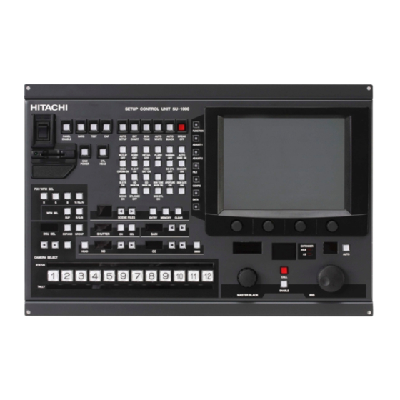
Page 15: Facility Names And Functions
Facility names and functions (Front) 3. 3. 3. 3. Facility names and functions 3.1 FRONT VIEW POWER SWITCH SCENE FILES SU power switch. SHUTTER / GAIN / ND/CC FILTER Camera power switch CAMERA SELECT AUTO SETUP section MASTER BLACK / IRIS ON/OFF SWITCH section LCD DISPLAY MENU button and rotary encoder. - Page 16 Facility names and functions (Rear) 3.2 REAR VIEW EXPAND data connecter VE SW IN connector (15 pin) Camera can be selected from Video Engeer Connect external DSU to control more than console via this connector. 12 cameras See Service information section. SWITCHER CTL connector (15 pin) Use for parallel control switcher.
- Page 17 Facility names and functions (Front) POWER switch on/off Set SCU Power switch to on. - PANEL ENABLE : - BARS : Color BAR on/off - TEST : TEST picture on/off - CAP : Camera CAP MODE - SD CARD : SD CARD slot - CAM POWER : Camera power on/off - CTL HEAD : Cameraman control enable AUTO SETUP SELECTION...
- Page 18 Facility names and functions (Front) PIX / WFM select Scene file select / Shutter,GAIN,ND,CC select Camera select Select the camera 1 to STATUS off: not connected , yellow: camera power off , green: camera power on (normal state) TALLY red: red tally , green: green tally , yellow: both red and green tally on...
- Page 19 Facility names and functions (Front) Iris, Master black control, camera number display and call bottom. LCD Display Select display menu from left side item bottum. Adjust menu item by using rotary encoder knobs.
-
Page 20: Lcd Menu
LCD menu 4. MENU structure... - Page 21 LCD menu 5.1 LCD MENU 5.1.1 OPERATION menu (FUNCTION) & description. Item Setting Factory Description setting CLEAR ND 1:CLEAR ND 2:CROSS Selects ND filters ND 3:1/16ND ND 4:1/64ND CC A:3200K 3200K CC B:4300K CC C:5600K Selects CC(ECC) filters CC D:6300K CC:E:8000K -3dB,0dB,3dB~...
- Page 22 LCD menu 5.2 ADJUST-1 MENU 5.2.1 GENERAL menu (ADJUST-1) & description. ADJUST-1 GENERAL DETAIL MASKING GAMMA Item Setting Factory Description BLACK GAIN FLARE GAMMA TABLE setting KNEE KNEE WHITE KNEE WHITE POINT SLOPE CLIP SHADING BLACK BLACK CLEAR STRETCH -128 to +127 Adjusts the black balance manually -128 to +127...
- Page 23 5.2.2 DETAIL menu (ADJUST-1) & description. ADJUST-1 GENERAL DETAIL MASKING DETAIL LEVEL BOOST DETAIL CRISP LEVEL DEPEND FREQ KNEE Item Setting Factory Description KNEE DETAIL BALANCE DETAIL SOURCE setting CLEAR DETAIL LEVEL TOTAL -128 to +127 Adjusts the detail level DETAIL LEVEL -128 to +127 TOTAL...
- Page 24 5.2.3 MASKING menu (ADJUST-1) & description. ADJUST-1 GENERAL DETAIL MASKING Item Setting Factory Description LINEAR 1 LINEAR 2 Ye-R Cy-G Mg-B setting SKIN TONE CHROMA MASKING G-Ye B-Cy R-Mg LINEAR 1 -64 to +63 CLEAR Adjusts the linear masking -64 to +63 LINEAR 1 -64 to +63 LINEAR 2...
- Page 25 5.2.4 SKIN DETAIL menu (ADJUST-1) & description. ADJUST-1 GENERAL DETAIL MASKING Item Setting Factory Description CH/GATE HIGH THRESHOLD SELECT CHROMA setting -128 to +127 LEVEL CLEAR Adjusts the CH1 skin tone PHASE Ye-R,R-Mg,Mg-B,B-Cy,Cy-G,G-Ye detail parameter manually PHASE FINE -128 to +127 LEVEL PHASE PHASE FINE...
- Page 26 5.3 ADJUST-2 MENU 5.3.1 SYSTEM TIMING menu (ADJUST-2) & description. ADJUST-2 SYSTEM SD DETAIL ON/OFF TIMING Item Setting Factory Description TIMING TIMING LEVEL setting HD TIMING Adjusts the HD timing for CLEAR H PHASE external sync -128 to +127 SD TIMING HD TIMING H PHASE SDI H PHASE...
- Page 27 5.3.3 ON/OFF menu (ADJUST-2) & description. ADJUST-2 SYSTEM SD DETAIL ON/OFF TIMING Item Setting Factory Description ASPECT COMB HD MODE 16:9 FILTER ON 1080i setting 16:9 ASPECT Selects aspect ratio COMB FILTER Selects comb filter on/off 1080i HD MODE Selects HDTV scan mode 720P ADJUST-2 SYSTEM...
- Page 28 LCD menu 5.4 FILE MENU 5.4.1 SCENE FILE select description. Press SCENE0,1,..,8, or PRESET, then the file data is set to a camera( or cameras) immediately. (ex. The SCENE2 data is memorized to the SCENE1 ) (1)Press the SCENE2, then the SCENE2 file is selected. (2)Press MEMORY, then press the SCENE1.
- Page 29 5.5 CONFIG MENU 5.5.1 DATE/TIME menu (CONFIG) & description. CONFIG Item Setting Factory Description DATE/TIME BUZZER SWITCHER setting DATE TIME YEAR From 2000 to 2099 Japanese MONTH From 1 to 12 date From 1 to 31 HOUR From 0 to 23 24 hours indication only MINUTE From 00 to 59...
- Page 30 5.5.4 SWITCHER menu (CONFIG) & description. CONFIG The signal that control serial switcher is output. DATE/TIME BRIGHT BUZZER SWITCHER OTHERS (Only serial switcher of FOR-A) FOR-A 5.5.5 OTHERS menu (CONFIG) & description. CONFIG Prohibit AUTO-SETUP when TALLY is ON. OTHERS DATE/TIME BRIGHT BUZZER...
- Page 31 LCD menu 5.6 DATA MENU 5.6.1 Data transfer Initial message if no items are selected. Press FROM , then choose source camera with a camera select buttom Press , then choose destination cameras with a camera select buttom 1 to Select transfer items.
- Page 32 5.6.2 SD CARD SAVE: Press SAVE , then choose the camera with a camera select buttom Press START to begin saving data from the selected camera to SD card. LOAD: Press LOAD , then choose the cameras with a camera select buttom 1 to Select the SD card data by pushing up,down bottom and back,next page bottom, reversed item is selected data number.
- Page 33 5.7 GROUP CONTROL Press GROUP , then choose the cameras for simultaneous control with the camera select bottom. Set on/off switch , analog control , auto setup, file select, etc. for simultaneous control, except Adjust-2 system timing menu.
-
Page 34: Specifications
Specifications 6. Specifications (1) Number of controllable cameras - Internal DSU only: 12 - External DSU(DU-1000): 48 (2) GROUP control - GROUP POWER ON/OFF - GROUP AUTO SETUP (3) Analog manual adjustment using the rotary encoder (4) On/off control (5) Display using the fluorescent display panel The large LCD display panel can display items such as the camera model name, camera No., camera status, adjustment items and percentage indication. - Page 35 Specifications (11) SCU FUNCTION restriction All control items are inhibited when the PANEL ENABLE SWITCH is off: (12) External VIDEO SWITCHER control The external VIDEO SWITCHER switching signal is output in conjunction with the camera select section. (13) Built-in VE switch input interface The camera can be selected in conjunction with switching of the VE switch.
- Page 36 Specifications Dimensions Unit :...
- Page 37 Specifications Connector pin diagram RS-232C(9pin D-sub male:RDED-9P-LNA(4-40)(55)) Plug CU mainframe Signal RX_232C (IN) TX_232C (OUT) RTS (OUT) CTS (IN) *RTS:Request To Send *CTS:Clear To Send WFM CONTROL (15pin female:YKF42-8043N) Plug CU mainframe Signal WFM CTL0 WFM CTL1 WFM CTL2 WFM CTL3 WFM CTL4 WFM CTL5 WFM CTL6...
-
Page 38: Service Information
Service information CCU 1-12 (4 pin female:HR10A-7R-4S(73)) Combined connector: HR10A-7P-4P Signal SD (TX) SD (RX) - Page 39 Service information...
Need help?
Do you have a question about the SU-1000 and is the answer not in the manual?
Questions and answers