Table of Contents
Advertisement
Advertisement
Table of Contents

Related Manuals for Craftsman 82339


Summary of Contents for Craftsman 82339
-
Page 1: Digital Multimeter
Owner's Manual Digital MultiMeter Model No. 82339 • Safety CAUTION: Read, understand and follow Safety Rules and Operating • Operation Instructions in this manual before • Maintenance using this product. • Español Sears, Roebuck and Co., Hoffman Estates, IL 60179 www.craftsman.com... -
Page 2: Table Of Contents
TABLE OF CONTENTS Page Warranty Safety Instructions Safety Symbols Control and Jacks Symbols and Annunciators Specifications Battery Installation Operating Instructions Data Hold Backlight Range Indicator Input Shutters DC Voltage Measurements AC Voltage Measurements DC Current Measurements AC Current Measurements Resistance Measurements Continuity Check Diode Test Capacitance Measurements... -
Page 3: Warranty
ONE YEAR FULL WARRANTY ON CRAFTSMAN MANUAL RANGING MULTIMETER If this CRAFTSMAN Manual Ranging MultiMeter fails to give complete satisfaction within one year from the date of purchase, RETURN IT TO THE NEAREST SEARS STORE OR OTHER CRAFTSMAN OUTLET IN THE UNITED STATES, and Sears will replace it, free of charge. -
Page 4: Safety Instructions
SAFETY INSTRUCTIONS This meter has been designed for safe use, but must be operated with caution. The rules listed below must be carefully followed for safe operation. NEVER apply voltage or current to the meter that exceeds the specified maximum: Input Limits Function Maximum Input... -
Page 5: Safety Symbols
SAFETY SYMBOLS This symbol adjacent to another symbol, terminal or operating device indicates that the operator must refer to an explanation in the Operating Instructions to avoid personal injury or damage to the meter. This WARNING symbol indicates a potentially WARNING hazardous situation, which if not avoided, could result in death or serious injury. -
Page 6: Control And Jacks
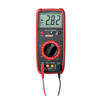
CONTROLS AND JACKS 2000 count Liquid Crystal Display Power switch Function Switch mA current input jack 10A current input jack Backlight pushbutton. Data Hold pushbutton Voltage, resistance and capacitance positive input jack Common negative input jack SYMBOLS AND ANNUNCIATORS Continuity Low Battery Diode Data Hold... -
Page 7: Specifications
SPECIFICATIONS Function Range Resolution Accuracy DC Voltage 200mV 0.1mV !(0.5% reading + 1 digit) (V DC) !(0.5% reading + 3 digits) 10mV 200V 100mV 1000V !(0.8% reading + 3 digits) AC Voltage 200mV 0.1mV !(1.2% reading + 5 digit) (V AC) (50/60Hz) !(1.0% reading + 5 digits 10mV... - Page 8 SPECIFICATIONS NOTE: Accuracy specifications consist of two elements: • (% reading) – This is the accuracy of the measurement circuit. • (+ digits) – This is the accuracy of the analog to digital converter. NOTE: Accuracy is stated at 64 F to 82 F (18 C to 28...
-
Page 9: Battery Installation
SPECIFICATIONS Operating Temperature F to 104 F (0 C to 40 Storage Temperature F to 122 F (-10 C to 50 Relative Humidity <70% operating Operating Altitude 2000 meters (7000ft.) maximum. Operating Humidity Max 70% up to 87ºF (31ºC) decreasing linearly to 50% at 122ºF (50ºC) Weight 12.34oz. -
Page 10: Operating Instructions
OPERATING INSTRUCTIONS WARNING: Risk of electrocution. High-voltage circuits, both AC and DC, are very dangerous and should be measured with great care. 1. ALWAYS press the POWER switch to the OFF position when the meter is not in use. 2. If “1” appears in the display during a measurement, the value exceeds the range you have selected. -
Page 11: Dc Voltage Measurements
DC VOLTAGE MEASUREMENTS CAUTION: Do not measure DC voltages if a motor on the circuit is being switched ON or OFF. Large voltage surges may occur that can damage the meter. 1. Set the function switch to the highest V DC position. 2. -
Page 12: Dc Current Measurements
DC CURRENT MEASUREMENTS 1. Insert the black test lead banana plug into the negative (COM) jack. 2. For current measurements up to 200mA DC, set the function switch to the highest DC mA position and insert the red test lead banana plug into the (mA) jack. -
Page 13: Resistance Measurements
RESISTANCE MEASUREMENTS WARNING: To avoid electric shock, disconnect power to the unit under test and discharge all capacitors before taking any resistance measurements. Remove the batteries and unplug the line cords. 1. Set the function switch to the highest !! position. 2. -
Page 14: Diode Test
DIODE TEST WARNING: To avoid electric shock, do not test any diode that has voltage on it. 1. Set the function switch to position. 2. Insert the black test lead banana plug into the negative (COM) jack. Insert the red test lead banana plug into the positive (V) jack. 3. -
Page 15: Maintenance
MAINTENANCE WARNING: To avoid electric shock, disconnect the test leads from any source of voltage before removing the back cover or the battery or fuse doors. WARNING: To avoid electric shock, do not operate your meter until the battery and fuse doors are in place and fastened securely. This MultiMeter is designed to provide years of dependable service, if the following care instructions are performed: 1. -
Page 16: Replacing The Fuses
WARNING: To avoid electric shock, do not operate your meter until the battery door is in place and fastened securely. REPLACING THE FUSES WARNING: To avoid electric shock, disconnect the test leads from any source of voltage before removing the fuse door. 1. -
Page 17: Troubleshooting
82375 Fuse kit 93894 9V Battery 82378 Set of black and red Test Leads 82339-DB Replacement battery door 82339-CS Rear cover screws For replacement parts shipped directly to your home Call 9 am – 5 pm eastern, M - F...
Need help?
Do you have a question about the 82339 and is the answer not in the manual?
Questions and answers