Table of Contents
Advertisement
Available languages
Available languages
Advertisement
Table of Contents

Related Manuals for Craftsman 82141


Summary of Contents for Craftsman 82141
- Page 1 Model No. 82141 • Safety CAUTION: Read, understand and • Operation follow Safety Rules and Operating Instructions in this manual before • Maintenance using this product. • Espafiol © Sears, Roebuck and Co., Hoffman Estates, IL 60179 U.S.A. www.craftsman.com 070606...
-
Page 2: Table Of Contents
r:_ :] i :[o] |o[o] _/ / _ _/ 1_ Page Warranty Safety Instructions Safety Symbols Control and Jacks Symbols and Annunciators Specifications Battery Installation Operating Instructions DC Voltage Measurements AC Voltage Measurements DC Current Measurements AC Current Measurements Resistance Measurements Continuity Check Diode Test... -
Page 3: Warranty
Manual Ranging MultiMeter fails togive complete satisfaction within o ne year from the date ofpurchase, RETURN ITTO THE NEAREST SEARS STORE OR OTHER CRAFTSMAN OUTLET THE UNITED STATES, and Sears will r eplace it,free ofcharge. Ifthis CRAFTSMAN Manual Ranging MultiMeter... - Page 4 This meter has been d esigned forsafe use, but m ust beoperated with caution. The rules l isted b elow m ust be carefully followed forsafe o peration. 1. NEVER apply voltage orcurrent tothe meter that e xceeds specified maximum: Input Limits Function Maximum...
- Page 5 3_'I _ I=II l i'db_'d;4 :[o]l This symbol adjacent to another symbol, terminal or operating device indicates that the operator must refer to an explanation in the Operating Instructions to avoid personal injury or damage to the meter. L WARN,NG This WARNING symbol indicates a potentially hazardous situation, which if not avoided, could result...
-
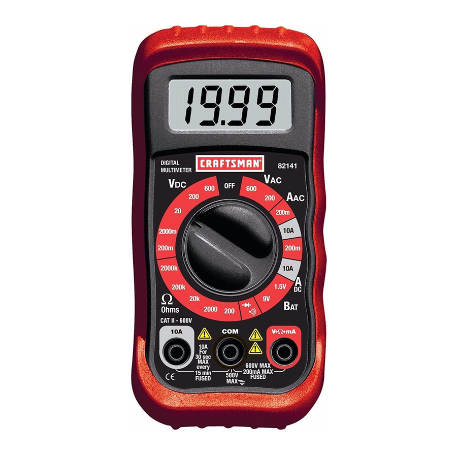
Page 6: Controls And Jacks
o_o]_IIII_,To] L',]F:I _Ie]LnlT:T_ [(_ LCD Display Function switch COM jack 10A jack Positive jack Note: Tilt stand, fuse and battery compartment are on rear of unit. H =O __k, | __ k, k, __ O_ •))) Continuity Diode test milli ( volts, amps) kilo (ohms) £_ ohms... -
Page 7: Specifications
Function Resolution Range Accuracy 200mV 0.1mV DC Voltage 2000mV (V DC) 0.01V +(0.5% reading + 2 digits) 200V 0.1V 600V 200V 0.1V AC Voltage +(1.5% reading + 5 digits 600V (V AC) (50/60Hz) DC Current 200mA 100pA +(1.2% reading + 2 digits) 10mA (A DC) +(2.0% reading + 2 digits) -
Page 8: Continuity Check
Diode T est Test current of 1 mA maximum, open circuit voltage 2.8V DC typical Continuity Check Audible signal will sound if the resistance is less than approximately 30£2 Battery Test current 9V (6mA); 1.5V (100mA) >1M£2 Input Impedance ACV Bandwidth 45Hz to 450Hz 200mV DCA voltage... -
Page 9: Battery Installation
I WARNING: To avoid electric shock, disconnect the test leads from any source of voltage before removing the battery door. Disconnect the test leads from the meter. Remove the protective rubber holster (if installed)_._t Open the battery door by loosening the screw using a Phillips head screwdriver. -
Page 10: Dc Voltage Measurements
J WARNING: Risk of electrocution. High-voltage circuits, both AC and DC, J are very dangerous and should be measured with great care. 1. ALWAYS turn the function switch to the OFF position when the meter is not in use. 2. If "1" appears in the display during a measurement, the value exceeds the range you have selected. -
Page 11: Ac Voltage Measurements
AC VOLTAGE MEASUREMENTS WARNING: Risk of Electrocution. The probe tips may not be long enough to contact the live parts inside some 240V outlets for appliances because the contacts are recessed deep in the outlets. As a result, the reading may show 0 volts when the outlet actually has voltage on it. -
Page 12: Dc Current Measurements
DC CURRENT MEASUREMENTS longer than 30 seconds. Exceeding 30 seconds may cause damage to I CAUTION: Do not make current measurements on the 10A scale for the meter and/or the test leads. Insert the black test lead banana plug into the negative (COM) jack. -
Page 13: Ac Current Measurements
AC CURRENT MEASUREMENTS longer than 30 seconds. Exceeding 30 seconds may cause damage to I CAUTION: Do not make current measurements on the 10A scale for the meter and/or the test leads. 1. Insert the black test lead banana plug into the negative (COM) jack. -
Page 14: Resistance Measurements
RESISTANCE MEASUREMENTS test and discharge all capacitors before taking any resistance ARNING: To avoid electric shock, disconnect power to the unit under measurements. Remove the batteries and unplug the line cords. 1. Set the function switch to the highest £2 position. Insert the black test lead banana plug into the negative (COM) jack Insert the red test lead banana plug into the... -
Page 15: Diode Test
DIODE TEST 1. Insert the black t est l ead b anana plug i nto the negative COM jack and the red test l ead b anana plug into the positive diode jack. 2. Turn t he function switch tothe.1_1-/o))) position. - Page 16 source ofvoltage before removing the back c over orthe battery orfuse I WARNING: Toavoid e lectric shock, disconnect the test l eads from any doors. I WARNING: Toavoid e lectric shock, donot o perate your meter until the battery and fuse doors are inplace a nd fastened securely.
-
Page 17: Battery Installation
REPLACING BATTERIES WARNING: To avoid electric shock, disconnect the test leads from any source of voltage before removing the battery door. When the batteries become exhausted or drop below the operating voltage, '_" will appear in the lower left corner of the LCD display. The batteries should be replaced. - Page 18 / _,(olUJ:] III:[_."]:[olo]l i I _ [€ There may be times when your meter does not operate properly. Here are some common problems that you may have and some easy solutions to them. Meter Does Not Operate: 1. Always read all the instructions in this manual before use.
- Page 19 82141 • Seguridad PRECAUCION: Lea, comprenda • Operaci6n siga las Reglas Seguridad e • Mantenimiento Instrucciones de operaci6n en este manual antes de usar el producto. • Espafiol © Sears, Roebuck and Co., Hoffman Estates, IL 60179 U.S.A. www.sears.com/craftsman 070606...
- Page 20 r.'1 :] IF.'1e]:[e[e] _/ / :1_IIe]_ Pagina Garantia Instrucciones de Seguridad Se_ales de Seguridad Control y Conectores Simbolos y Anunciadores Especificaciones Instalaci6n de la Bateria Instrucciones de operaci6n Medici6n de Voltaje CD Medici6n de Voltaje CA Medici6n de corriente CD Medici6n de corriente CA Medidas de resistencia Verificaci6n de Continuidad...
- Page 21 GARANTiA TOTAL POR UN ANO PARA EL MULTiMETRO ESCALA MANUAL DE CRAFTSMAN Si este Multimetro de escala manual CRAFTSMAN no le satisface totalmente dentro de un a_o a partir de la fecha de compra, REGR#:SELO A LA TIENDA SEARS O DISTRIBUIDOR...
- Page 22 Este m edidor hasido disefiado para uso seguro, sinembargo, debe s er operado con precauci6n. Para u na operaci6n segura, debera cumplir las reglas enumeradas acontinuaci6n. 1. NUNCA aplique almedidor voltaje ocorriente que exceda los limites maximos especificados dealimentaci6n: Limites deentrada Funci6n Entrada maxima 600V C D/CA...
- Page 23 •"t : 1_r:_I :_1 J] :1_"] :[rllJ _IIJT:_ ! ± Esta seSal adyacente a otra seSal, terminal o dispositivo en operaci6n indica que el operador debera buscar una explicaci6n en las Instrucciones operaci6n para evitar lesiones a su persona o daSos al medidor.
- Page 24 _o] _/ / _._[o] I :F."]k'|o[o]_I:[O,]l I [o]_._] :F: Pantalla LCD Selector de Funci6n Enchufe COM Enchufe 10A Enchufe positivo Nota: El soporte inclinado, fusible y compartimiento de bateria estan atras de la unidad. _ _v4 : [o] I(o_."]1:111 _IJ][__,I JIo] _,,1 :[_ •))) Continuidad Prueba de diodo...
- Page 25 _,..-'.) -..,1 =[e,] I _1 [___[e,] [e] _I_ Funci6n Escala Resoluci6n Precisi6n 200mY 0.1mY Voltaje CD 2000mY (V CD) 0.01V +(0.5% lectura + 2 digitos) 200V 0.1V 600V 200V 0.1V Voltaje CA +(1.5% lectura + 5 digitos 600V (V CA) (50/60Hz) Corriente CD 200mA...
- Page 26 _,,,-,,) _ =[e,] I _1 [e,7'__[e,] [e]ZI=[_ Prueba de diodo Corriente maxima de prueba de 1mA, voltaje de circuito abierto 2.8V DC tipica Verificaci6n de continuidad Se emitira una seSal audible si la resistencia es aproximadamente menor a 30£_ Prueba de corriente de la bateria 9V (6mA);...
- Page 27 I__1 Ir_,q IF_,Te,] [_ _IIe):11 IF_,1 : T_,_I I1:1 _ ,_ prueba de cualquier fuente de voltaje antes de quitar la tapa de la I ADVERTENClA: Para evitar choque electrico, desconecte los cables de bateria. 1. Desconecte los cables de prueba del medidor. Quite la funda protectora de hule (siesta instalada_.._ Abra la tapa de la bateria aflojando el tornillo con un...
- Page 28 O" I ADVERTENCIA: Riesgo de electrocuci6n. Los circuitos de alta tensi6n, CA y CD son muy peligrosos y deberan ser medidos con gran cuidado. 1. SIEMPRE gire el conmutador de funci6n a la posici6n de apagado (OFF) cuando el medidor no este en uso. 2.
- Page 29 MEDICION DE VOLTAJE CA ADVERTENCIA: Riesgo de electrocuci6n. Las puntas de las sondas pueden no ser Io suficientemente largas para hacer contacto con las partes vivas dentro de algunos contactos 240V para electrodomesticos debido a que dichos contactos estan muy adentro del contacto. Como resultado, la lectura puede indicar 0 voltios cuando en realidad el contacto si tiene tensi6n.
- Page 30 MEDICION DE CORRIENTE durante mas de 30 segundos. Exceder 30 segundos puede causar I PRECAUCION: No tome medidas de corriente en la escala de 10A dafios al medidor y/o a los cables de prueba. Inserte el conector banana del cable negro de prueba en el enchufe negativo (COM).
- Page 31 MEDICION DE CORRIENTE durante mas de 30 segundos. Exceder 30 segundos puede causar I PRECAUCION: No tome medidas de corriente en la escala de 10A dafios al medidor y/o a los cables de prueba. 1. Inserte el conector banana del cable negro de prueba en el enchufe negativo (COM).
- Page 32 MEDIDAS DE RESISTENCIA ADVERTENCIA: Para evitar choque electrico, desconecte la tensi6n a la unidad bajo prueba y descargue todos los capacitores antes de tomar cualquier medidas de resistencia. Retire las baterias y desconecte los cordones de linea. 1. Fije el selector de funci6n en la posici6n £_mas alta.
- Page 33 PRUEBA DE DIODO 1, Inserte el conector banana del cable rojo de prueba en el enchufe negativo COM y el conector banana del cable rojo de prueba en el enchufe positivo de diodo. Gire el selector rotativo a la posici6n-I_l./o))). Toque las sondas de prueba al diodo bajo prueba.
- Page 34 ADVERTENClA: Para e vitar choque electrico, desconecte los cables de prueba decualquier fuente devoltaje antes dequitar latapa posterior ladelabateria ofusibles. ADVERTENClA: Para e vitar choque electrico, noopere e lmedidor a menos que latapa posterior ylatapa d elabateria yfusibles esten colocadas yaseguradas.
- Page 35 REEMPLAZO DE BATERiAS ADVERTENCIA: Para evitar choque electrico, desconecte los cables prueba de cualquier fuente de voltaje antes de quitar la tapa de la bater{a, Cuando las baterias se agoten o caigan bajo el voltaje de operaciSn, aparecera "1_1"del lado derecho de la pantalla LCD. Debera reemplazar las baterias.
- Page 36 Habra ocasiones enque sumedidor nofuncione correctamente. seguida encontrara algunos problemas comunes que puede Ilegar atenet yalgunas soluciones faciles. El m edidor nofunciona: 1.Siempre lea todas las instrucciones eneste manual antes deusar. 2.Verifique que labateria esta b ien instalada. 3.Verifique que labateria esta e nbuenas condiciones. 4.Si labateria esta e nbuen e stado yelmedidor aun nofunciona, revise el fusible para a segurar...
Need help?
Do you have a question about the 82141 and is the answer not in the manual?
Questions and answers