Table of Contents
Advertisement
Advertisement
Table of Contents

Related Manuals for Craftsman 82344


Summary of Contents for Craftsman 82344
- Page 1 Owner’s Manual Auto-Ranging MultiMeter Model 82344 • Safety CAUTION: Read, understand and • Operation follow Safety Rules and Operating Instructions in this manual before • Maintenance using this product. • Español © Sears, Roebuck and Co., Hoffman Estates, IL 60179 U.S.A.
-
Page 2: Table Of Contents
TABLE OF CONTENTS Page Warranty Safety Instructions Safety Symbols Control and Jacks Symbols and Annunciators Specifications Battery Installation Operating Instructions DC Voltage Measurements AC Voltage Measurements AC/DC Current Measurements Resistance Measurements Capacitance Measurements Frequency Measurements Temperature Measurements Continuity Test Diode Test Data Hold Low Battery Auto-Ranging... -
Page 3: Warranty
ONE YEAR FULL WARRANTY ONE YEAR FULL WARRANTY ON CRAFTSMAN MULTIMETER If this CRAFTSMAN Multimeter fails to give complete satisfaction within one year from the date of purchase, RETURN IT TO THE NEAREST SEARS STORE OR OTHER CRAFTSMAN OUTLET IN THE UNITED STATES, and Sears will replace it, free of charge. -
Page 4: Safety Instructions
SAFETY INSTRUCTIONS This meter has been designed for safe use, but must be operated with caution. The rules listed below must be carefully followed for safe operation. NEVER apply voltage or current to the meter that exceeds the specified maximum: Input Protection Limits Function Maximum Input... -
Page 5: Safety Symbols
SAFETY SYMBOLS This symbol adjacent to another symbol, terminal or operating device indicates that the operator must refer to an explanation in the Operating Instructions to avoid personal injury or damage to the meter. This WARNING symbol indicates a WARNING potentially hazardous situation, which if not avoided, could result in death or serious injury. -
Page 6: Control And Jacks
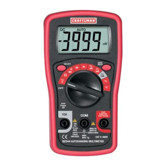
CONTROLS AND JACKS 1. LCD Display 2. DATA HOLD button 3. SELECT button 4. Function switch 5. Positive input jack 6. COM jack 7. 10A jack 8. Rubber boot Note: Tilt stand and battery access is on the rear of unit. SYMBOLS AND ANNUNCIATORS AC (voltage) DC (direct current or voltage) -
Page 7: Specifications
SPECIFICATIONS Function Range Accuracy DC Voltage 400.0mV ±(0.5% reading + 4 digits) (V DC) 4.000V 40.00V ±(0.8% reading + 4 digits) 400.0V 600V AC Voltage 50-60Hz 40-400Hz (V AC) 4.000V ±(0.8% rdg + 4 d) 40.00V ±(2% rdg + 5 ±(1.2% rdg + 5 d) 400.0V 600V... - Page 8 SPECIFICATIONS Function Range Accuracy Capacitance 4.000nF Not specified 40.00nF ±(3.0% reading + 10 digits) 400.0nF 4.000 F 40.00 F Not Specified 100 F Frequency 10.00Hz 100Hz ±(1.0% reading + 4 digits) 1.000kHz 10Hz to 1MHz 10.00kHz Sensitivity: 5.0Vrms 100.0kHz 1.000MHz 5.000MHz Not specified Temp °F -40 to...
- Page 9 SPECIFICATIONS Diode Test Test current of 0.6mA maximum, open circuit voltage 1.5V DC typical Continuity Check Audible signal will sound if the resistance is less than approximately <30 Temperature sensor Requires type K thermocouple Input Impedance 10M (V AC/DC) Display 3999 count LCD Overrange “OL”...
-
Page 10: Battery Installation
BATTERY INSTALLATION WARNING: To avoid electric shock, disconnect the test leads from any source of voltage before removing the battery/fuse cover. 1. Disconnect the test leads from the meter. 2. Remove the rubber holster (if in place). 3. Remove the two screws securing the rear cover using a Phillips head screwdriver. -
Page 11: Operating Instructions
OPERATING INSTRUCTIONS WARNING: Risk of electrocution. High-voltage circuits, both AC and DC, are very dangerous and should be measured with great care. 1. ALWAYS turn the function switch to the OFF position when the meter is not in use. 2. Press the HOLD button to freeze a displayed reading NOTE: On some low AC and DC voltage ranges, with the test leads not connected to a device, the display may show a random, changing reading. -
Page 12: Ac Voltage Measurements
AC VOLTAGE MEASUREMENTS WARNING: Risk of Electrocution. The probe tips may not be long enough to contact the live parts inside some 240V outlets for appliances because the contacts are recessed deep in the outlets. As a result, the reading may show 0 volts when the outlet actually has voltage on it. -
Page 13: Ac/Dc Current Measurements
AC/DC CURRENT MEASUREMENTS CAUTION: Do not make high current measurements on the 10A scale for longer than 15 seconds followed by a 15 minute cool down period. Exceeding 15 seconds may cause damage to the meter and/or the test leads. 1. -
Page 14: Resistance Measurements
RESISTANCE MEASUREMENTS 1. Insert the black test lead banana plug into the negative COM jack and the red test lead banana plug into the positive jack. 2. Set the function switch to the position. 3. Touch the test probe tips across the circuit or part under test. -
Page 15: Temperature Measurements
TEMPERATURE MEASUREMENTS WARNING: To avoid electric shock, disconnect test leads from any source of voltage before making a temperature measurement. Be sure that the thermocouple has been removed before changing to any other measurement function. 1. Insert the type K thermocouple probe into the Temp and COM jacks. -
Page 16: Diode Test
DIODE MEASUREMENTS 1. Insert the black test lead banana plug into the negative COM jack and the red test lead banana plug into the positive V/ /mA jack. 2. Turn the rotary switch to the •))) position. 3. Touch the test probes to the diode under test. Forward voltage will indicate 0.4V to 0.7V. -
Page 17: Maintenance
MAINTENANCE WARNING: To avoid electric shock, disconnect the test leads from any source of voltage before removing the battery/fuse cover. WARNING: To avoid electric shock, do not operate your meter until the battery/fuse cover is in place and fastened securely. This Multimeter is designed to provide years of dependable service, if the following care instructions are performed. -
Page 18: Replacing The Batteries
REPLACING THE BATTERIES WARNING: To avoid electric shock, disconnect the test leads from any source of voltage before removing the battery cover. 1. When the batteries become exhausted or drop below the operating voltage, “ ” will appear in the LCD display. The batteries should be replaced. -
Page 19: Troubleshooting
Electrical Testing (Item No. 82303) at your local Sears store. 2. Call our Customer Service Line 1-888-326-1006. SERVICE AND PARTS Item Number Description 82374 Fuse kit 93891 AAA battery 82378 Set of black and red Test Leads 82344-CS Rear cover screws 82377 Replacement Temperature Probe...
Need help?
Do you have a question about the 82344 and is the answer not in the manual?
Questions and answers
I have the black probe in the common and red in the V. Ohm and selector on Continuity and the probes touching and there is no sound
There is no sound when testing continuity because the resistance of the circuit or device under test is likely greater than approximately 30 ohms. The buzzer only sounds if the resistance is less than about 30 ohms.
This answer is automatically generated
On my meter when I test for voltage the outlet reads 4.12 shouldn’t it be 110 or higher?
Your Craftsman 82344 multimeter may be reading 4.12 volts instead of 110V or higher due to one of the following reasons:
1. Incorrect Range Selection – Ensure the multimeter is set to the correct AC voltage range (e.g., 600V AC) rather than a lower range.
2. Faulty Test Leads – Check if the test leads are properly connected and not damaged.
3. Weak Battery – A low battery can affect the accuracy of readings. Replace the battery if necessary.
4. Loose or Poor Contact – Ensure the probes are making firm contact with the outlet.
5. Defective Fuse – If the fuse is blown, it may affect measurement accuracy. Check and replace if needed.
6. Meter Malfunction – If all else fails, the meter may have an internal issue requiring service.
Try troubleshooting these issues to ensure accurate voltage readings.
This answer is automatically generated