Table of Contents
Advertisement
Quick Links
Advertisement
Table of Contents

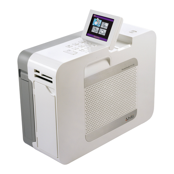
Related Manuals for HiTi Digital P110S Pocket Studio


Summary of Contents for HiTi Digital P110S Pocket Studio
-
Page 1: Service Guide
CONFIDENTIAL P110S Service Guide Version: 1.11... -
Page 2: Revision History
CONFIDENTIAL Revision History Date Revision Description Remark 2009/10 1.0.0 The first edition. 2010/6/25 1.0.1 1. Disassmbly out of warranty warning Page 19 2. Modified Error code list Page 59 2011/1/6 1.0.2 Disassmbly warning Page 19 2012/2/8 1. Added jitter pitch (interval) Page 60 2. -
Page 3: Table Of Contents
CONFIDENTIAL Outlines: CHAPTER 1: INTRODUCTION.......... 4 CHAPTER 2: SPECIFICATIONS ........5 CHAPTER 3: OPERATION THEORY........ 6 CHAPTER 4: DISASSEMBLY & ASSEMBLY ....19 ASSY_CASE_LEFT, ASM_ID_CASE_RIGHT, CHASSIS ASSY ..20 LCD PANEL BD, ASM_LCD..............23 CARD BD ....................25 MAIN BD....................27 SMART CARD BD ................28 WIRE SNR JAM P110S .................30 WIRE SNR RIBBON P110S..............32 WIRE SNR CAM P110S................33... -
Page 4: Chapter 1: Introduction
CONFIDENTIAL Chapter 1: Introduction This document contains operation theory and parts replacement procedures that are intended to ease the task of transportation, usage, maintenance and parts replacement. -
Page 5: Chapter 2: Specifications
CONFIDENTIAL Chapter 2: Specifications Item Description 300 x 300 dpi Resolution Max Prints Size 4 “x6 “ 63 sec./ 4”x 6” photo paper and 1x1 sticker Printing time/ size Capacity 60 pieces Ribbon Capacity 60 images for YMCO Display 2.5” LCD 320x240 pixel Memory Card Slot CF Type I &... -
Page 6: Chapter 3: Operation Theory
CONFIDENTIAL Chapter 3: Operation Theory Hardware P110S Circuit Theory The circuit of P110S contain six parts: main board, card board, LCD board, motors and sensors wires/cables. The power is supplied by adapter and Li-ion battery. Adapter is an AC to DC power conversion device and it provides a 90W max. - Page 7 CONFIDENTIAL parallel processing of control and computation operations, and the unified memory architecture (UMA) eliminates the memory cost. Besides, versatile general peripherals are also to provide the data communication capability. 2. Memory IC a. SDRAM This 256Mbit SDRAM on main board is to be the data buffer. The image file, print data, video frame are temporarily stored during operation.
- Page 8 CONFIDENTIAL Smart card sensor Jam sensor Ribbon sensor Paper out sensor Cam sensor LE sensor Ribbon type sensor b. Cam sensor Cam sensor (2 pcs) indicates the position of linkage. There are four position: P1-initial position, P2-Load paper position, P3-ribbon search position, P4-print position. Penetration Type Sensor c.
- Page 9 CONFIDENTIAL d. Smart card/ Ribbon type sensor Detect ribbon type and sheet and whether the ribbon install. e. Ribbon LED Detect ribbon color Y, M, C and O, which are index as black bar individually. Reflective Type Sensor 4. TPH Interface Print data will be shifted into TPH during each clock.
- Page 10 CONFIDENTIAL Charging IC is MAXIM1640. There are three charging modes Top-off mode, Fast-charge mode, and Pulsetrickle mode. Pulse-trickle mode is for battery in over-discharge situation. Fast-charge is for battery in normal voltage. Top-off is after fast-charge mode for charging battery voltage upto full voltage (21V).
- Page 11 CONFIDENTIAL Mechanism & Movements User Interface...
- Page 12 CONFIDENTIAL...
- Page 13 CONFIDENTIAL...
- Page 14 CONFIDENTIAL Function layout Cam Motor Main Board Ribbon Lock Module Capstan Motor ADF translation parts Takeup TQL Supply TQL Capstan Roller ASSY LINKAGE Cam gear train Lifter Linkage rotate axes Exit Paper gear train...
-
Page 15: Printing Process
CONFIDENTIAL Printing Process Job start Error !! Paper exist ? Move Cam to P4 Paper Out Print Y Move Cam to P3 Move Cam to P3 Error !! Search RBN Y Ribbon Out Search RBN M,C,O Move Cam to P2 Move Cam to P4 Paper feeding... -
Page 16: Cam Position
CONFIDENTIAL Cam Position Ribbon Search Paper Feeding Paper Feeding Paper Moving Function (Linkage) (TQL _Take) (Roller_Pick-Up) (Lifter) (Paper Guide) Initial Disable Disable Disable Paper Feeding P2 Disable Enable Enable Search Ribbon P3 Enable Disable Disable Printing Enable Disable Disable Down Initial (P1) Ribbon cassette is released. - Page 17 CONFIDENTIAL Paper Feeding (P2) Ribbon cassette is locked. Lifter is up. Roller_Pick-Up is enable. TQL_Take is disable. Search Ribbon (P3) Lifter is down. Roller_Pick-Up is disable. TQL_Take is enable.
-
Page 18: Paper Path
CONFIDENTIAL Printing (P4) Lifter is down. Roller_Pick-Up is disable. TQL_Take is enable. Paper path... -
Page 19: Chapter 4: Disassembly & Assembly
CONFIDENTIAL Chapter 4: Disassembly & Assembly Safety Instructions Read these instructions carefully. Save these instructions for future reference. Follow all warnings and instructions marked on the printer. Before disassembly, it should be off the switch and removed the batter pack and plug of power cord. Any Main BD or Card BD damage related to disassembly will be judged as “out-of-warranty”... -
Page 20: Assy_Case_Left, Asm_Id_Case_Right, Chassis Assy
CONFIDENTIAL Maintenance Parts Replacement Procedures 48.P2501.001 Parts Name ASSY_CASE_LEFT, Part No. 47.P2509.001 ASM_ID_CASE_RIGHT, CHASSIS DH.P2536.001 ASSY Screwdriver Procedure No. Tools Maintenance part: ASSY_CASE_LEFT, ASM_ID_CASE_RIGHT and CHASSIS ASSY [Step 1] Open the door and remove 5 screws which hold ASSY_CASE_LEFT. - Page 21 CONFIDENTIAL [Step 2] Turn the printer to the bottom. Remove 2 screws . [Step 3] Remove the 2 flat cables that connect with MAIN BD then remove ASM_ID_CASE_RIGHT.
- Page 22 CONFIDENTIAL [Step 4] Remove the connector that connects with MAIN BD. [Step 5] Press this ID_BUTTON_PAPER_CASSETTE to take CHASSIS ASSY out. CHASSIS ASSY ASSY_CASE_LEFT ASM_ID_CASE_RIGHT [Step 6] Assemble it in the reverse order of the disassembly procedure.
-
Page 23: Lcd Panel Bd, Asm_Lcd
CONFIDENTIAL Maintenance Parts Replacement Procedures Parts Name LCD PANEL BD, ASM_LCD Parts No. 45.P25RB.M21 48.P2524.001 Tools Screwdriver Procedure No. Maintenance part: LCD PANEL BD Maintenance part:ASM_LCD [Step 1] Remove the ASSY_CASE_LEFT, ASM_ID_CASE_RIGHT and CHASSIS ASSY according to Procedure No. [Step 2] Remove the connector that connects with CARD BD from the ASM_ID_CASE_RIGHT. [Step 3] Lift up ASM_LCD then remove 2 screws. - Page 24 CONFIDENTIAL [Step 4] Take out ASM_LCD and turn the ASM_LCD to the back side. Remove 2 screws. [Step 5] Remove front case of ASM_LCD then remove the 2 connectors that connect with LCD PANEL [Step 6] Pull up and push LCD PANEL BD to the left side then remove LCD PANEL BD. [Step 7] Assemble it in the reverse order of the disassembly procedure.
-
Page 25: Card Bd
CONFIDENTIAL Maintenance Parts Replacement Procedures Parts Name CARD BD Parts No. 45.P25R3.042 Tools Screwdriver Procedure No. Maintenance part: CARD BD [Step 1] Remove the ASSY_CASE_LEFT, ASM_ID_CASE_RIGHT and CHASSIS ASSY according to Procedure No. [Step 2] Remove the connector that connects with CARD BD from the ASM_ID_CASE_RIGHT. - Page 26 CONFIDENTIAL [Step 3] Remove 5 screws from the ASM_ID_CASE_RIGHT then take the CARD BD set out. [Step 4] Release 6 clutches that hold the CARD BD then take out the CARD BD. [Step 5] Assemble it in the reverse order of the disassembly procedure.
-
Page 27: Main Bd
CONFIDENTIAL Maintenance Parts Replacement Procedures Parts Name MAIN BD Parts No. 45.P25R1.072 Tools Screwdriver Procedure No. Maintenance part: MAIN BD [Step 1] Remove the ASSY_CASE_LEFT, ASM_ID_CASE_RIGHT and CHASSIS ASSY according to the Procedure No. [Step 2] Remove 10 connectors and 1 flat cable which connect with MAIN BD. Remove 2 screws to take MAIN BD out. -
Page 28: Smart Card Bd
CONFIDENTIAL Maintenance Parts Replacement Procedures Parts Name SMART CARD BD Parts No. 45.P25R8.M11 Tools Screwdriver Procedure No. Maintenance part: SMART CARD BD [Step 1] Remove the ASSY_CASE_LEFT, ASM_ID_CASE_RIGHT and CHASSIS ASSY according to the Procedure No. [Step 2] Move and hold that ASSY LINKAGE. [Step 3] Release 2 clutches that hold the SMART CARD BD then take SMART CARD BD and 2 springs out. - Page 29 CONFIDENTIAL take SMART CARD BD out. [Step 5] Assemble it in the reverse order of the disassembly procedure.
-
Page 30: Wire Snr Jam P110S
CONFIDENTIAL Maintenance Parts Replacement Procedures Parts Name WIRE SNR JAM P110S Parts No. 40.P2501.R01 Tools Screwdriver Procedure No. Maintenance part: WIRE SNR JAM P110S (JAM SENSOR) [Step 1] Remove the ASSY_CASE_LEFT, ASM_ID_CASE_RIGHT and CHASSIS ASSY according to the Procedure No. [Step 2] Remove the flat cable and connector that connects with MAIN BD. - Page 31 CONFIDENTIAL [Step 4] Remove the screw and take WIRE SNR JAM P110S out. [Step 5] Assemble it in the reverse order of the disassembly procedure.
-
Page 32: Wire Snr Ribbon P110S
CONFIDENTIAL Maintenance Parts Replacement Procedures Parts Name WIRE SNR RIBBON P110S Parts No. 40.P2502.R01 Tools Screwdriver Procedure No. Maintenance part: WIRE SNR RIBBON (RIBBON SENSOR) [Step 1] Remove the ASSY_CASE_LEFT, ASM_ID_CASE_RIGHT and CHASSIS ASSY according to the Procedure No. [Step 2] Cut the binder and remove 2 screws then remove the connector that connects with MAIN [Step 3] Remove 2 screws then take WIRE SNR RIBBON P110S out. -
Page 33: Wire Snr Cam P110S
CONFIDENTIAL Maintenance Parts Replacement Procedures Parts Name WIRE SNR CAM P110S Parts No. 40.P2503.R01 Tools Screwdriver Procedure No. Maintenance part: WIRE SNR CAM P110S (CAM SENSOR) [Step 1] Remove the ASSY_CASE_LEFT, ASM_ID_CASE_RIGHT and CHASSIS ASSY according to the Procedure No. [Step 2] Remove the connector that connects with MAIN BD. - Page 34 CONFIDENTIAL [Step 4] Take out (1) DU_CAM_RBN_ADF (56.P2507.001) and (2) DU_LINK_CAM (51.P2508.001). [Step 4] Remove 1 screw then take WIRE SNR CAM P110S out. [Step 5] Assemble it in the reverse order of the disassembly procedure.
-
Page 35: Wire Mb To Smart_Card Bd P110S
CONFIDENTIAL Maintenance Parts Replacement Procedures Parts Name WIRE MB TO SMART_CARD BD P110S Parts No. 40.P2504.R01 Tools Screwdriver Procedure No. Maintenance part: WIRE MB TO SMART_CARD BD P110S [Step 1] Remove the ASSY_CASE_LEFT, ASM_ID_CASE_RIGHT and CHASSIS ASSY according to the Procedure No. -
Page 36: Wire Snr Ribbon_Type P110S
CONFIDENTIAL Maintenance Parts Replacement Procedures Parts Name WIRE SNR RIBBON_TYPE P110S Parts No. 40.P2505.R01 Tools Screwdriver Procedure No. Maintenance part: WIRE SNR RIBBON_TPYE P110S (RIBBON TYPE SENSOR) [Step 1] Remove the ASSY_CASE_LEFT, ASM_ID_CASE_RIGHT and CHASSIS ASSY according to the Procedure No. [Step 2] Remove the connector that connects with MAIN BD. - Page 37 CONFIDENTIAL [Step 4] Remove the screw then take WIRE SNR RIBBON_TPYE P110S out. [Step 5] Assemble it in the reverse order of the disassembly procedure.
-
Page 38: Wire Snr Paper_Out P110S
CONFIDENTIAL Maintenance Parts Replacement Procedures Parts Name WIRE SNR PAPER_OUT P110S Parts No. 40.P2508.R01 Tools Screwdriver Procedure No. Maintenance part: WIRE SNR PAPER_OUT P110S (PAPER OUT SENSOR) [Step 1] Remove the ASSY_CASE_LEFT, ASM_ID_CASE_RIGHT and CHASSIS ASSY according to the Procedure No. [Step 2] Remove the MAIN BD according to the Procedure No. - Page 39 CONFIDENTIAL [Step 4] Turn the printer to another side and remove 2 screws then take WIRE SNR PAPER_OUT P110S out. [Step 5] Assemble it in the reverse order of the disassembly procedure.
-
Page 40: Wire Snr Le P110S
CONFIDENTIAL Maintenance Parts Replacement Procedures Parts Name WIRE SNR LE P110S Parts No. 40.P2506.R01 Tools Screwdriver Procedure No. Maintenance part: WIRE SNR LE P110S (LEADING EDGE SENSOR) [Step 1] Remove the ASSY_CASE_LEFT, ASM_ID_CASE_RIGHT and CHASSIS ASSY according to the Procedure No. [Step 2] Remove the MAIN BD according to the Procedure No. - Page 41 CONFIDENTIAL [Step 4] Remove 3 screws, C-ring, E-ring and 3 gears from the left side. 1. 65.P2510.001 (KF_GEAR_32T_P110 ) 2. 65.P2511.001 (KF_GEAR_40T_P110 ) 3. 65.P2514.001 (KF_GEAR_ONEWAY_EXIT_P110 ), 53.P2503.001(ONEWAY) [Step 5] Remove 2 screws , E-ring and C-ring then take DU_CAM_RBN_ADF (56.P2507.001) out from the right side.
- Page 42 CONFIDENTIAL 1. 65.P2521.001 (KF_HELICAL-GEAR_PULLEY_CAP_P110 ) 2. 56.P2572.001 (FLANGE_BELT_P110 ) 3. 46.P2501.001 (TQL_TAKE_P110 ), 65.P2523.001 (GEAR_TQL_BOT_P110), 65.P2524.001 (GEAR_TQL_TOP_P110 ) 4. 65.P2519.001 (KF_HELICAL-GEAR_28T_12T_P110) 5. 65.P2520.001 (KF_HELICAL-GEAR_24T_P110 ) 6. 59.P2501.001 (BELT_S2M_P110 ) [Step 7] Pull up ASSY FRAME LOCK RBN. ASSY FRAME LOCK RBN [Step 8] Remove screw form the ASM_FRAME_TRAY_FRONT.
- Page 43 CONFIDENTIAL [Step 10] Turn the CHASSIS ASSY to the back side then remove 2 screws. [Step 11] Pull up ASM_FRAME_TRAY_FRONT.
- Page 44 CONFIDENTIAL [Step 12] Remove 2 screws from two sides. [Step 13] Take the ASS_PLATE_LE out and remove 2 screws then take WIRE SNR LE P110S out. [Step 14] Assemble it in the reverse order of the disassembly procedure.
-
Page 45: Roller_Capstan_Tuk_P110
CONFIDENTIAL Maintenance Parts Replacement Procedures Parts Name ROLLER_CAPSTAN_TUK_P110 Parts No. 53.P2528.001 53.P2528.002 Tools Screwdriver Procedure No. There are 2 types of Captsan roller Capstan Roller: From 53.P2528.001 to 53.P2528.002 Also need to use different Pulley: From 65.P2521.001 (KF_HELICAL-GEAR_PULLEY_CAP_P110 ) to 65.P2521.015 (KF_HELICAL-GEAR_PULLEY_CAP_P110) Maintenance part: ROLLER_CAPSTAN_TUK_P110 (CAPSTAN ROLLER) [Step 1] Remove the ASSY_CASE_LEFT, ASM_ID_CASE_RIGHT and CHASSIS ASSY according... -
Page 46: Assy Roller Pinch
CONFIDENTIAL [Step 5] Assemble it in the reverse order of the disassembly procedure. Maintenance Parts Replacement Procedures Parts Name ASSY ROLLER PINCH Parts No. 48.P2503.001 Tools Screwdriver Procedure No. Maintenance part: ASSY ROLLER PINCH (PINCH ROLLER) [Step 1] Remove the ASSY_CASE_LEFT, ASM_ID_CASE_RIGHT and CHASSIS ASSY according to the Procedure No. - Page 47 CONFIDENTIAL [Step 4] Remove 2 C-rings and 2 bushings from both sides then and take ASSY ROLLER PINCH out. [Step 5] Assemble it in the reverse order of the disassembly procedure.
-
Page 48: Fan 4010 12Vdc Adda 2-Ball System Rohs
CONFIDENTIAL Maintenance Parts Replacement Procedures Parts Name FAN 4010 12VDC ADDA 2-BALL Parts No. 17.FAP25.BA1 SYSTEM ROHS Tools Screwdriver Procedure No. Maintenance part: FAN 4010 12VDC ADDA 2-BALL SYSTEM ROSH (FAN) [Step 1] Remove the ASSY_CASE_LEFT, ASM_ID_CASE_RIGHT and CHASSIS ASSY according to the Procedure No. - Page 49 CONFIDENTIAL [Step 4] Assemble it in the reverse order of the disassembly procedure.
-
Page 50: Mtr Cam Pm 15 22Ohm Bip P110S
CONFIDENTIAL Maintenance Parts Replacement Procedures Parts Name MTR CAM PM 15 22OHM BIP P110S Parts No. 17.MCP25.BM1 Tools Screwdriver Procedure No. Maintenance part: MTR CAM PM 15 22OHM BIP P110S (CAM MOTOR) [Step 1] Remove the ASSY_CASE_LEFT, ASM_ID_CASE_RIGHT and CHASSIS ASSY according to the Procedure No. -
Page 51: Mtr Pm 3.75 7Ohm Bip P110S Rohs
CONFIDENTIAL Maintenance Parts Replacement Procedures Parts Name MTR PM 3.75 7OHM BIP P110S ROHS Parts No. 17.MAP25.BM1 Tools Screwdriver Procedure No. Maintenance part: MTR PM 3.75 7OHM BIP P110S ROHS (CAPSTAN MOTOR) [Step 1] Remove the ASSY_CASE_LEFT, ASM_ID_CASE_RIGHT and CHASSIS ASSY according to the Procedure No. - Page 52 CONFIDENTIAL [Step 4] Remove 2 screws from the right side. [Step 5] Move MAIN BD (No need to unplug connectors) then take MTR PM 3.75 7OHM BIP P110S ROHS out. [Step 6] Assemble it in the reverse order of the disassembly procedure.
-
Page 53: Tph 300Dpi P110S Tsb 6.3-Degree Rohs
CONFIDENTIAL Maintenance Parts Replacement Procedures Parts Name TPH 300DPI P110S TSB 6.3-DEGREE Parts No. 37.P3240.T01 ROHS Tools Screwdriver Procedure No. Maintenance part: TPH 300DPI P110S TSB 6.3-DEGREE ROHS (TPH) [Step 1] Remove the ASSY_CASE_LEFT, ASM_ID_CASE_RIGHT and CHASSIS ASSY according to the Procedure No. - Page 54 CONFIDENTIAL Please note that the cable of the TPH should be assembled in the correct position as following:...
-
Page 55: Chapter 5: Adjustment
CONFIDENTIAL Chapter 5: Adjustment Please make sure you got the latest version of troubleshooting tool- “HTools” from HiTi (service2@hiti.com). CAM Position Alignment POWER BD Adjustment (Printout density adjustment) Base on the TPH value which mentions on the TPH label to get voltage value from the list below and select voltage value on HTools. - Page 56 CONFIDENTIAL Voltage Voltage Voltage Voltage Voltage Voltage Value Value Value Value Value Value 3300 15.592 3183 15.313 3066 15.029 2949 14.739 2832 14.444 2715 14.143 3297 15.585 3180 15.306 3063 15.022 2946 14.732 2829 14.436 2712 14.135 3294 15.578 3177 15.299 3060 15.014...
-
Page 57: Chapter 6: Gear List
CONFIDENTIAL Chapter 6: Gear List Left side Item PN Description 65.P2502.001 DU_GEAR_CAM_15_80_P110 65.P2504.001 DU_GEAR_CAM_31_P110 65.P2504.001 DU_GEAR_CAM_31_P110 65.P2503.001 DU_GEAR_CAM_18_50_P110 65.P2501.021 DU_GEAR_CAM_13_45_P110 65.P2505.021 DU_GEAR_CAM_38_P110 65.P2506.002 DU_RACK_LINKAGE_P110 65.P2510.001 KF_GEAR_32T_P110 65.P2511.001 KF_GEAR_40T_P110 L10 65.P2514.001 KF_GEAR_ONEWAY_EXIT_P110... - Page 58 CONFIDENTIAL Right side Item PN Description 56.P2507.002 DU_CAM_RBN_ADF_P110 65.P2507.001 KF_GEAR_25T_P110 R3-1 65.P2524.001 GEAR_TQL_TOP_P110 R3-2 46.P2501.001 KF_TQL_TAKE_P110 R3-3 65.P2523.001 GEAR_TQL_BOT_P110 65.P2516.001 KF_GEAR_SWING_25T_P110 65.P2519.001 KF_HELICAL-GEAR_28T_12T_P110 65.P2521.003 KF_HELICAL-GEAR_PULLEY_CAP_P110 56.P2572.003 FLANGE_BELT_P110 65.P2520.003 KF_HELICAL-GEAR_24T_P110...
- Page 59 CONFIDENTIAL 56.C0192.H02 SC_PS_IDLE_PINCH_C1 65.P2515.001 KF_GEAR_PULLEY_DRIVER_P110 56.P2576.002 FLANGE_PULLEY_P110 65.P2509.001 KF_GEAR_30T_P110 47.P2503.001 ASSY TQL SUPPLY 65.P2512.001 KF_GEAR_45T_20T_P110 65.P2507.001 KF_GEAR_25T_P110 65.P2507.001 KF_GEAR_25T_P110 65.P2516.001 KF_GEAR_SWING_25T_P110 65.P2508.001 KF_GEAR_30T_17T-MXL_P110 65.P2507.001 KF_GEAR_25T_P110 65.P2516.001 KF_GEAR_SWING_25T_P110 65.P2507.001 KF_GEAR_25T_P110 65.P2516.001 KF_GEAR_SWING_25T_P110 65.P2507.001 KF_GEAR_25T_P110 65.P2515.001 KF_GEAR_PULLEY_DRIVER_P110 56.P2539.001 KF_FLANGE_PULLEY_D4_P110 65.P2522.001 KH_PULLEY_FEED_ROLLER_P110 56.P2565.001 FLANGE_PICK_UP_PULLY 65.P2513.001 GEAR_MXL24T_P110...
-
Page 60: Chapter 7: Error Message
CONFIDENTIAL Chapter 7: Error Message RED LED Error Message Possible Cause Solution blinking times 1. Chip of ribbon cartridge is contaminated, 1.Clean chip of ribbon cartridge. or poor contact. 2.Change Door Sensor/Ribbon Ribbon Missing 2. Door/Ribbon Cassette Sensor is NG. Cassette Sensor. - Page 61 CONFIDENTIAL Jitter Pitch (Interval) Parts Dimension interval Capstan 21.9912 Platen Roller 3 4 . 5 5 Pulley Capstan 21.9912 Pulley Capstan (Pulley Tooth) 1.0472 Pulley Capstan (Gear Tooth) 0.6468 Pulley Drive (Pulley) 15.708 Pulley Drive (Pulley Tooth) 1.0472 Pulley Drive (Gear Tooth) 8 1 0.193925926 Gear_Motor 1 5 2.908888889...
- Page 62 TEL: +86-512-8228-1688 FAX: +86-512-8228-1690 United States (North America) 727 Brea Canyon Rd. Suite#2 Walnut, CA 91789, U.S.A. TEL: +1-909-594-0099 FAX: +1-909-598-0011 Netherlands (Europe) HiTi Digital Europe B.V. Ekkersrijt 1331, 5692 AJ Son, The Netherlands TEL: +31 4.99.46.28.60 FAX:+31 4.99.46.12.99 India...
Need help?
Do you have a question about the P110S Pocket Studio and is the answer not in the manual?
Questions and answers