Table of Contents
Advertisement
Quick Links
Publicly traded on NASDAQ
Symbol: NSSC
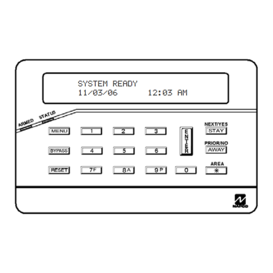
CONTROL PANEL/COMMUNICATOR
Programming the F-64 Control Panel with the F-64PROG Programmer
Quick Start using the F-64PROG:
1. Refer to the wiring diagram and connect the Siren, Aux. Power, PGM Output, Remote
2. Connect AC power first and then the battery.
3. Configure the Touchpad (see page 40).
4. Access the Easy Menu Driven Program Mode:
© NAPCO 2006
R
F R E E D O M F - 6 4
SYSTEM READY
11/03/06
Bus, earth ground, Zone and Telephone wiring.
NOTE: See Installation Instructions (WI1501).
Press 456789 R
Default Dealer Code
Press NO (Q) until "ACTIVATE PROGRAM Y/N" appears on the programmer display.
Press YES (P) to Enter Dealer Program Mode. Go to page 5.
PROGRAMMING
INSTRUCTIONS
12:03 AM
F-64PROG Programmer
WI1502A 9/06
Advertisement
Table of Contents

Related Manuals for NAPCO FREEDOM F-64


Summary of Contents for NAPCO FREEDOM F-64
- Page 1 4. Access the Easy Menu Driven Program Mode: Press 456789 R Default Dealer Code Press NO (Q) until “ACTIVATE PROGRAM Y/N” appears on the programmer display. Press YES (P) to Enter Dealer Program Mode. Go to page 5. © NAPCO 2006 WI1502A 9/06...
-
Page 2: Important Notice
Differences between the GEM-P1664 and the Freedom F-64 Control Panels: The GEM-P1664 control panel and the Freedom F-64 V30 control panel are identical, except for the following: • The "Classic" Gemini RP-Series keypads cannot be used with the Freedom F-64 V30 control panel. -
Page 3: Table Of Contents
Dealer Code ..............11 ADDRESS NUMBER INDEX ...........53 Test Timer ..............11 Clear Dealer Program ..........11 F-64 WIRING DIAGRAM ..........56 Cold Start ..............11 Refer to accompanying F-64 Installation Instructions (WI1501) for installation information. Freedom F-64 Programming Instructions NAPCO Security Systems... -
Page 4: Control Panel Programming Options
Similarly, a high-speed local download may be made in the field using a notebook or laptop computer. Connect JP2 on the control panel to a Napco PCI-MINI computer interface using the 6-conductor cable supplied. (Refer to PCI-MINI Instal- lation Instructions WI767). -
Page 5: Dealer Program Mode
Should it be necessary to create a new custom default pro- gram, (a) from the Dealer Program Mode, press the button to enter the Direct Address Program Mode; (b) access Location 2285 (Clear Program); (c) press and start over. Freedom F-64 Programming Instructions NAPCO Security Systems... -
Page 6: Easy Menu Driven Program Menu
Valid entries are from 01 to 64. Directly enter each zone number, including leading zeros. • Press to save and repeat for any additional zone(s); press the NEXT/YES button to proceed. (Direct Entry) NOTE: 24 Hour Zones will automatically be programmed as audible (Burg Output). Freedom F-64 Programming Instructions NAPCO Security Systems... -
Page 7: Chime Zones In Area 1
Press YES to enable Telco Line Fault Test. Enable Telco • Line Test? Press NO to continue. NOTE: If enabled, a Telco Line Fault Test Delay of 60 sec. will auto- matically be programmed. (Press YES or NO) Freedom F-64 Programming Instructions NAPCO Security Systems... -
Page 8: Enable Burg Output Chirp On Keyfob
Enter Freedom " listed above. K P ? Y / N KeyPad # • Press NO to skip this selection and jump to Central Station Receiver 1 Telephone Number (Direct Entry) (see next page). Freedom F-64 Programming Instructions NAPCO Security Systems... -
Page 9: Central Station Receiver 1 Telephone Number
Example: Program a code of “2222” for user 02, with area 1 options of “Arm/ Disarm” and “User Program”. Enter “2222” for a user code, “• (blank) 9” for area 1 options and “• (blank) •(blank)” for area 2 options. Freedom F-64 Programming Instructions NAPCO Security Systems... -
Page 10: Rf Transmitter Points
NEXT/YES button to proceed when all keyfobs have been entered. NOTE: When programming the ID Code number, “0” through ”9” = through ; A = ; B = ; D = ; E = and “F” = Freedom F-64 Programming Instructions NAPCO Security Systems... -
Page 11: Keyfob Transmitters As Zone Input Devices
This erases all programmed data (Dealer Program, Zone Description Data and Schedules). Access address 2286 and press . Data entry is not allowed. NOTE: Some features 2 2 8 6 X X (schedules) can only be programmed again with the Downloading Software. Freedom F-64 Programming Instructions NAPCO Security Systems... -
Page 12: Entering Zone Descriptions
(after entering the first digit, the cursor will automatically advance to the second digit). When the second zone number digit is entered, the cursor will automatically advance to the right, allowing the description locations to be entered. Always press to save each zone description. Freedom F-64 Programming Instructions NAPCO Security Systems... -
Page 13: Direct Address Program Mode
"bit numbers" 1,3,4 and 6, respec- tively. DETERMINE THE DATA ENTRIES 1. Referring to ZONE FEATURES in the Programming Worksheets that follow, the Exit/Entry Follower for Zones 1 through 8 are located at address 0916. Freedom F-64 Programming Instructions NAPCO Security Systems... -
Page 14: Decimal Format Example
"ACTIVATE PROGRAM", scroll backward using 3. Press to enter the Address Program Mode. Address "0000" will display. 4. Press to access Address 1417. The existing data will display and the cursor will ad- 1417 Freedom F-64 Programming Instructions NAPCO Security Systems... -
Page 15: Hexadecimal Format Example
¼sec. = 1 sec. blank (•) ¼sec. = 1.25 sec. blank (•) ¼sec. = 1.5 sec. blank (•) ¼sec. = 1.75 sec. 2 seconds blank (•) ¼sec. = 2 sec. ¼sec. = 63.25 Freedom F-64 Programming Instructions NAPCO Security Systems... -
Page 16: Programming Conventions Used In This Manual
It is recommended that the panel be uploaded to NAPCO's PCD-Windows software following any F-64PROG programmer changes and that the PCD-Windows's error-check feature be utilized to reduce the possibility of programming omissions or conflicts. -
Page 17: System Delays & Timeouts
1. Enter delay/timeout in corresponding address locations above. Note: All entries for address 1418 are in quarter seconds (.25 seconds). Therefore, the default of 008 results in a 2 second timeout. 2. Press to save. Freedom F-64 Programming Instructions NAPCO Security Systems... -
Page 18: System Output Timeouts
Pager report will now appear as “983 22 1234”. NOTE: See CS Receiver Options to select Pager Format. Pager Format 1. Enter in 1st and 2nd Leading Digits as shown (right nibble). (2nd Digit) 2. Valid entries are: 0-9. Press to save. [Default = blank (•) blank (•)] Freedom F-64 Programming Instructions NAPCO Security Systems... -
Page 19: System Options
2045. For Touchpads, see "Ambush" glossary entry in install instructions WI1501. [Default = blank (•) blank (•)] Enter in address location (both 1st and 2nd digits); valid entries are 1-9. Press ENTER save. Note: Do not program in CP-01 compliant systems. Freedom F-64 Programming Instructions NAPCO Security Systems... - Page 20 Select the desired option entering the option number (1-8) for each digit. Enter corresponding option number in address location. NOTE: Dark shaded data value box shows option not available. Press Enter to save. Freedom F-64 Programming Instructions NAPCO Security Systems...
- Page 21 Address 2045 is left blank (•), then, the 2-digit “Global Ambush RESERVED Code” will be “99”. RESERVED ****NOTE: If this feature is not selected, the E15 Lug will, by default, activate when the system is armed (all areas). RESERVED RESERVED Freedom F-64 Programming Instructions NAPCO Security Systems...
-
Page 22: Cs Receiver Options
2. Enter up to 20 digits from left to right. NOTE: Leave trailing boxes blank (•). Press [Enter] to save. 3. Valid entries are: 1-9, B = button, C = button, D = 3 sec. pause, E = Wait for dial tone, F = Ignore location Freedom F-64 Programming Instructions NAPCO Security Systems... -
Page 23: Cs Subscriber Id Options
1. Enter 3 or 4 digits (depending on the CS receiver format) for each subscriber number from left to right. NOTE: Leave trailing boxes blank (•). 2. Valid entries are: 1-9, 0 and B-F. NOTE: A is not permitted. Press [Enter] or ON/OFF] to save. Freedom F-64 Programming Instructions NAPCO Security Systems... -
Page 24: Cs System Reporting Options
Disable Wait for Handshake on Transmit * NOTE: If neither Touch-tone Dialing nor Touch-tone w/Rotary Disable Auto Dial Tone Detect Backup is selected, then system defaults automatically to Rotary Dialing. Leave blank (•) to select Rotary Dialing. Freedom F-64 Programming Instructions NAPCO Security Systems... -
Page 25: Cs Zone Reporting Options
MODEM CODES determine the zone types reported for the following formats: SIA and ADEMCO Point ID. Gas Alarm 1. Select the desired Modem Code for each zone from the table shown. Heat Alarm Auxiliary Alarm 2. Press to save. 24 Hour Auxiliary Freedom F-64 Programming Instructions NAPCO Security Systems... -
Page 26: Cs User Reporting Options
Select the desired option entering the option number (1-8) for each digit. At the F-64PROG programmer, enter corresponding option number in address location. NOTE: Dark shaded data value box shows option not available. Press to save. Freedom F-64 Programming Instructions NAPCO Security Systems... -
Page 27: Ezm Group Options
Enabled PRIORITY AREA ARMING: Select option from the table shown. Enter either blank (•) or "1" in corresponding address location. NOTE: Dark shaded data value box shows option not available. Press to save. Freedom F-64 Programming Instructions NAPCO Security Systems... -
Page 28: Area Bell Control Options
(1,2,3,4) accordingly. For example, if you wish to grant an Area 1 keypad the ability to turn off an Area 2 PGM2 output, enter "2" in Address 1485. Enter digit in address location. NOTE: Dark shaded data value box shows option not available. Press to save. Freedom F-64 Programming Instructions NAPCO Security Systems... -
Page 29: Keypad / Touchpad Options
5. Exit Delay time must first be programmed to allow conversion from arming Stay to Away. 1. Select the desired zone by entering the zone number (001-064) for each address. 2. At the F-64PROG Programmer, enter corresponding zone number in address location. Press to save. Freedom F-64 Programming Instructions NAPCO Security Systems... -
Page 30: Zone Options - Zones 1 To 16
Select the desired zone option by entering the option number (1-8) for each selected zone. located on the bottom Enter corresponding option number in address location. of the next page. NOTE: Dark shaded data value box shows option not available. Press [Enter] to save. Freedom F-64 Programming Instructions NAPCO Security Systems... -
Page 31: Zone Options - Zones 17 To 32
• Fire is enabled for the zone number(s) entered in “FIRE ZONES ENTER ZONE #”. • 2-Wire Smoke Detector is enabled for the zone number(s) entered in “2-WIRE FIRE ZNS ENTER ZONE #”. Freedom F-64 Programming Instructions NAPCO Security Systems... -
Page 32: Zone Options - Zones 33 To 48
Select the desired zone option by entering the option number (1-8) for each selected zone. Enter corresponding option number in address location. NOTE: Dark shaded data value box shows option not available. Press [Enter] to save. Freedom F-64 Programming Instructions NAPCO Security Systems... -
Page 33: Zone Options - Zones 49 To 64
Pulse Alarm Output is enabled for the zone number(s) entered in “FIRE ZONES ENTER ZONE #” or “2-WIRE FIRE ZNS ENTER ZONE #”. Fire is enabled for the zone number(s) entered in “FIRE ZONES ENTER ZONE #”. 2-Wire Smoke Detector is enabled for the zone number(s) entered in “2-WIRE FIRE ZNS ENTER ZONE #”. Freedom F-64 Programming Instructions NAPCO Security Systems... -
Page 34: External Relay Control
1642 1643 1644 1645 1646 1647 1648 RELAY # AREA TIMEOUT EVENT ID COND. RELAY # AREA TIMEOUT EVENT ID COND. TO PROGRAM, SEE NEXT PAGE [Default = blank (•) from address 1489-1648]. Freedom F-64 Programming Instructions NAPCO Security Systems... -
Page 35: Options
5A. Select Alarm Type and Timeout Type from Table 5A (on next page); enter in corresponding left address location. 5B. Select Activation Conditions from Table 5B (on next page); enter in corresponding right address location. Continued Freedom F-64 Programming Instructions NAPCO Security Systems... - Page 36 Entry Relay Area 2 Entry Relay Area 3 * NOTE: Keypad Auxiliary is not to be selected for UL Installations. Entry Relay Area 4 NOTE: Keypad Tamper must be enabled in UL installations. Freedom F-64 Programming Instructions NAPCO Security Systems...
- Page 37 Napco Glass Break 2044 [Default = blank (•) from address 2029-2044]. Default = 8 (240 minutes) NOTE: These timers apply only to Supervised RF Transmitters (see "RF Transmitters" in Easy Menu Driven Program Mode). Freedom F-64 Programming Instructions NAPCO Security Systems...
-
Page 38: Clear Program Options
. Data entry is not allowed. NOTE: Some features (schedules) can only be programmed again with the Downloading Software. If power fails, time and date restarts at 00:00:00 and a date of 01-01-04 (January 1, 2004). Freedom F-64 Programming Instructions NAPCO Security Systems... -
Page 39: Dealer Program Mode Overview
01 (ZONE DESCRIPTIONS) Enter Date Enter Time Dealer Code Initial Configuration Only (new or memory cleared panel); Test Timer suppressed thereafter. Normal entry mode for previously programmed panel starts at "# AREA 1 KEYPADS". Freedom F-64 Programming Instructions NAPCO Security Systems... -
Page 40: Touchpad Configuration Mode
TOUCHPADS, below). At least one (1) Touchpad must be used; only one is required for a single-area Commercial Burglary installa- tion. The F-64TP Touchpad is one of four Touchpad designs within the NAPCO Freedom 64 Home Protection System. The three other Touchpad designs include: •... - Page 41 (displays Keypad Tamper system trouble "E11-XX", where XX is the address of the keypad detected by the panel). To disable the Tamper switch, press the NO button; to en- able, press YES. Default is "NO" (disabled). Press MENU to continue or press RESET to exit. Freedom F-64 Programming Instructions NAPCO Security Systems...
- Page 42 Secondary transmitter. The RF SS should be at least 50 points higher than the RF NOISE level. Press YES to display. Press NO or MENU to continue or press RESET to exit. To exit Touchpad Configuration Mode, press RESET. Freedom F-64 Programming Instructions NAPCO Security Systems...
-
Page 43: Touchpad Menu Mode
Key Mode" appears in the LCD Window with the "System Ready" message. The Master I-FOB MUST be inserted into the Touchpad for ACTIVATE this menu item to appear. (Press MENU to skip to the top of PIR TEST the list). Freedom F-64 Programming Instructions NAPCO Security Systems... -
Page 44: Easy Menu Programming Worksheets
Page 44 WI1502A 9/06 EASY MENU PROGRAMMING WORKSHEET - 1 OF 4 Freedom F-64 Programming Instructions NAPCO Security Systems... -
Page 45: Keyfob Transmitters
RF ID CHECK POINT XMTR # ZONE RF ID CHECK POINT (printed on xmtr box) (printed on xmtr box) KEYFOB # Area RF ID CHECK OPTION OPTION Keyfob Transmitters: (printed on xmtr box) Freedom F-64 Programming Instructions NAPCO Security Systems... - Page 46 A B C D E F G H I J K L M N O P Q R S T U V W X Y For Zones 33-64, see next page Dealer Code: Freedom F-64 Programming Instructions NAPCO Security Systems...
- Page 47 A B C D E F G H I J K L M N O P Q R S T U V W X Y For Zones 1-32, see previous Dealer Code: page Freedom F-64 Programming Instructions NAPCO Security Systems...
-
Page 48: Alphabetical Index
BACKLIGHT FOLLOW PIR, 40 CS SUBSCRIBER ID OPTIONS (ADDRESS 0560- 0667), 23 BINARY (BIT) FORMAT EXAMPLE, 13 CS SYSTEM REPORTING CODES, 24 BYPASS ENABLE, 10 CS SYSTEM REPORTING OPTIONS (ADDRESS BYPASS OPEN ZONES?, 43 0670-0705), 24 Freedom F-64 Programming Instructions NAPCO Security Systems... - Page 49 ENABLE LOCAL ALARM ON FIRST ZONE AND TRIP 1420), 21 (ADDRESS 1421), 21 DISPLAY ALARM LOG, 43 ENABLE LOW SECURITY FIRE ALARM SILENCE, 20 DISPLAY FIRE ALARM, 43 ENABLE MANAGER'S MODE (ADDRESS 1421), 21 DISPLAY FIRE LOG, 43 Freedom F-64 Programming Instructions NAPCO Security Systems...
- Page 50 Page 50 WI1502A 9/06 ALPHABETICAL INDEX (CONT'D) ENABLE NO EOLR ZONES, 7 FREEDOM F-64 WIRING DIAGRAM, 60 ENABLE RESIDENTIAL FIRE (ADDRESS 1422), 21 FUNCTION MODE, 4 ENABLE SIA CP-01 FEATURES, 8 GEM-P1664 AND F-64 PANEL DIFFERENCES, 2 ENABLE TCP/IP COMMUNICATIONS (ADDRESS...
- Page 51 RF SUPERVISORY TIMERS, 37 WIRELESS TROUBLE ACTIVATES TELCO 1 RF TRANSMITTER POINTS, 10 (ADDRESS 1423), 21 RPT EXIT ERR/RECENT CLOSE (ADDRESS 2053), WIRELESS TROUBLE ACTIVATES TELCO 3 (ADDRESS 1423), 21 SECURITY BYPASS, 10 WIRING DIAGRAM, 60 Freedom F-64 Programming Instructions NAPCO Security Systems...
- Page 52 ZONE OPTIONS - ZONES 17 TO 32 (ADDRESS 1029- 1144), 31 ZONE OPTIONS - ZONES 33 TO 48 (ADDRESS 1157- 1272), 32 ZONE OPTIONS - ZONES 49 TO 64 (ADDRESS 1285- 1400), 33 ZONE RESPONSE, 41 Freedom F-64 Programming Instructions NAPCO Security Systems...
-
Page 53: Address Number Index
ENABLE ALARM OUTPUT ON TELCO FAIL ONLY WHEN ARMED ....(ADDRESS 1423) .............. 21 ENABLE AUTOARM IF NOT CLOSED AT END OF WINDOW ......(ADDRESS 1420) .............. 21 ENABLE CANCEL REPORT TO TELCO 3 ............(ADDRESS 2051) .............. 21 Freedom F-64 Programming Instructions NAPCO Security Systems... - Page 54 RESOUND ON WIRELESS SMOKE LOW BATTERY ......... (ADDRESS 1424) .............. 21 RF RECEIVER & SUPERVISORY TIMER OPTIONS .......... (ADDRESS 2029-2044) ............. 37 RF RECEIVER & SUPERVISORY TIMER OPTIONS .......... (ADDRESS 2056) .............. 37 RPT EXIT ERR/RECENT CLOSE ............... (ADDRESS 2053) .............. 21 Freedom F-64 Programming Instructions NAPCO Security Systems...
- Page 55 ZONE OPTIONS - ZONES 17 TO 32 ..............(ADDRESS 1029-1144) ............. 31 ZONE OPTIONS - ZONES 33 TO 48 ..............(ADDRESS 1157-1272) ............. 32 ZONE OPTIONS - ZONES 49 TO 64 ..............(ADDRESS 1285-1400) ............. 33 Freedom F-64 Programming Instructions NAPCO Security Systems...
-
Page 56: Wiring Diagram
Page 56 WI1502A 9/06 FREEDOM F-64 WIRING DIAGRAM Freedom F-64 Programming Instructions NAPCO Security Systems...
Need help?
Do you have a question about the FREEDOM F-64 and is the answer not in the manual?
Questions and answers