Table of Contents

Related Manuals for CDA edd61


Summary of Contents for CDA edd61
- Page 1 & edd91 Extractors Installation, Use and Maintenance Customer Care Department • The Group Ltd. • Harby Road • Langar • Nottinghamshire • NG13 9HY T : 01949 862 012 F : 01949 862 003 E : customer.care@cda.eu W : www.cda.eu www.cda.eu...
- Page 2 Appliance information: Please enter the details on the appliance rating plate below for reference, to assist CDA Customer Care in the event of a fault with your appliance and to register your appliance for guarantee purposes. Appliance Model...
- Page 3 IMPORTANT INFORMATION FOR CORRECT DISPOSAL OF THE PRODUCT IN ACCORDANCE WITH EC DIRECTIVE 2002/96/EC. At the end of its working life, the product must be taken to a special local authority waste collection centre or to a dealer providing appliance recycling services. Disposing of a household appliance separately avoids possible negative consequences for the environment and health.
- Page 4 • Steam cleaners must not be used when cleaning this appliance. • The performance of your extractor will vary depending on a number of factors. These include: type of extraction, length of ducting, room volume, ventilation available and cleanliness of the filters.
-
Page 5: Using Your Extractor
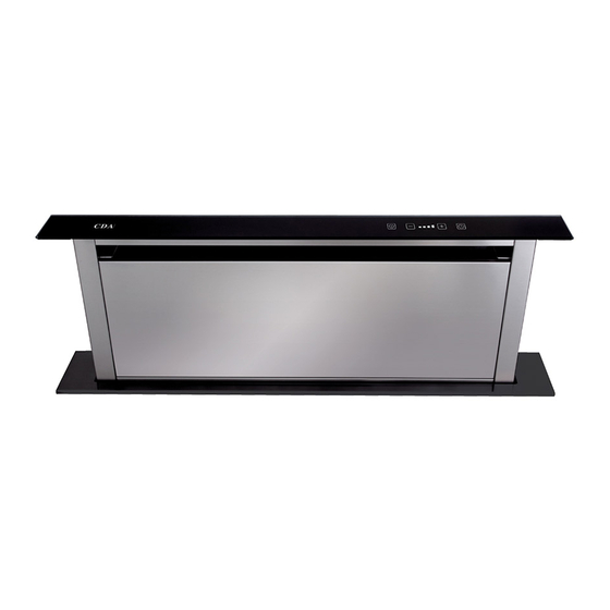
Using Your Extractor For best performance, you should switch on the extractor 15 minutes before starting to cook and leave it to run for approximately 15 minutes after the end of cooking. Fig. 1 Control Panel A - Off key B - On / “+”... - Page 6 To decrease the speed at any time • Touch the “-” key a few times, until the required speed is reached. To switch off the extractor • Touch the “Off” key : The moving panel will descend to its rest position and the appliance will continue extracting until its height drops below approx.
-
Page 7: Care And Maintenance
You can clean your extractor effectively by simply using a dilute solution of water and mild detergent and drying to a shine with a clean cloth, for example the CDA E-Cloth. Cleaning the grease filters The grease filters should be kept clean to minimise the risk of fire. - Page 8 To remove and replace the grease filters • Touch the “On/+” key so the moving panel raises to its full extent, Pull then isolate the power supply so it stays raised. • By pulling the two top corners of the Fig.
-
Page 9: Mounting Your Extractor
Mounting your Extractor When the extractor is to be installed behind an electric or gas hob, the minimum distance between the hob and extractor must exceed 50mm. In the case of a gas hob, the minimum distance from any burner to the back of the hob must also be 65mm. If the instructions provided with your gas hob state that the required distance between the hob and extractor must be greater than specified above, then that is the distance that should be observed;... -
Page 10: Troubleshooting
The circuit breaker or fuse has Check the circuit breaker or fuse. tripped. In the event of a fault with the extractor, please contact CDA Customer Care for assistance. Contact CDA Customer Care A: Customer Care Department, The CDA Group Ltd, Harby Road,... -
Page 11: Ducting And Ventilation
Ducting and Ventilation • For best performance and lowest noise output, we recommend the use of 150mm ducting. Use of any smaller ducting will reduce performance and increase noise. • The length of ducting should not exceed 5 metres in total. •... -
Page 12: Installation
Installation 560/860 Ø150 480/780 Fig. 3 Note • We recommend that you seek the help of another individual when installing this product. • The fixings supplied are suitable for most installations. It is the responsibility of the installer to ensure that the fixings are suitable for the cabinets in the property. - Page 13 Fig. 5 worktop to accommodate the extractor. The dimensions of the cut-out should be:- edd61 - 490 x 100mm edd91 - 790 x 100mm Fig. 6 5) If your extractor has been supplied with the motor unit already mounted on the main body, this needs to be...
- Page 14 6) Locate the support frame (trim piece); apply a narrow bead of silicone sealant to the underside of this (Fig. 7). Position this around the cut-out in the worktop (Fig. 8). 7) Lower the main body of the downdraft extractor through the support Fig.
- Page 15 9) Refit the motor unit to the main body of the downdraft extractor. This may be positioned with the outlet facing vertically upward or downward. 10) Connect suitable ducting to the extractor outlet. See page 11 for Fig. 10 ducting requirement details. 11) Position the metal box containing the electronic components in the cabinet, no closer than 65mm to any...
- Page 16 14) Open the filter cover (Figs. 14 & 15) then remove the grease filter package identified in Fig. 15. Pull 15) Position the grease filters as shown in Fig. 16. Fig. 14 Downdraft Calibration After installation it is necessary to calibrate the downdraft mechanism.
-
Page 17: Mains Electricity Connection
Mains Electricity Connection Warning! This appliance must be earthed. Green and Yellow to Earth Brown to Liv e 13 Amp fuse Cord Clamp Blue to Neutra l Fig. 17 The mains lead of this appliance has been fitted with a BS 1363A 3Amp fused plug. -
Page 18: Electrical Information
As the colours of the wires in the mains lead of this appliance may not correspond with the coloured markings identifying the terminals in your plug, proceed as follows:- • The wire which is coloured GREEN and YELLOW must be connected to the terminal which is marked with letter (E) or by the Earth symbol or coloured GREEN and YELLOW. - Page 19 E & O E. All instructions, dimensions and illustrations are provided for guidance only. CDA reserve the right to change specifications without prior notice.
- Page 20 T : 01949 862 012 F : 01949 862 003 E : customer.care@cda.eu Customer Care Department • The Group Ltd. • Harby Road • Langar • Nottinghamshire • NG13 9HY T : 01949 862 012 F : 01949 862 003 E : customer.care@cda.eu W : www.cda.eu www.cda.eu Copyright © CDA 2014...
Need help?
Do you have a question about the edd61 and is the answer not in the manual?
Questions and answers