
Related Manuals for Flash FTB-324-2


Summary of Contents for Flash FTB-324-2
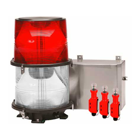
- Page 1 SERIAL NUMBER FTB 324-2, FTB 324-2LT Medium Intensity Obstruction Lighting System Reference Manual Part Number 7913242 Flash Technology, 332 Nichol Mill Lane, Franklin, TN 37067 (615) 261-2000...
-
Page 2: Front Matter
Flash Technology warrants all components, under normal operating conditions, for 2 years. Parts Replacement The use of parts or components, in this equipment, not manufactured or supplied by Flash Technology voids the warranty and invalidates the third party testing laboratory certification which ensures compliance with FAA Advisory Circulars 150/5345-43F, 150/5345-51 and 150/4345-53C. -
Page 3: Personnel Hazard Warning
Personnel Hazard Warning Dangerous Voltages Dangerous line voltages reside in certain locations in this equipment. Also, this equipment may generate dangerous voltages. Although FTCA has incorporated every practical safety precaution, exercise extreme caution at all times when you expose circuits and components, and when you operate, maintain, or service this equipment. -
Page 4: Table Of Contents
Table of Contents FTB 324-2, FTB 324-2LT ......................i Front Matter ..........................ii Abstract ..........................ii Copyright ..........................ii Trademark Acknowledgements .................... ii Applicable Specifications ..................... ii Disclaimer ..........................ii Warranty ..........................ii ... - Page 5 Flashhead .......................... 9 Photocell ......................... 10 Installation........................... 10 Power Converter Wiring ....................10 Flashhead Wiring ......................11 Photocell Wiring ......................11 Installation Checklist ...................... 11 Section 3 - Maintenance and Troubleshooting ............... 23 Safety ..........................
- Page 6 List of Figures Figure 1-1 – TB1 Alarm Contacts .................... 3 Figure 1-2 – 2903800 Board Configuration ................4 Figure 2-1 – Power Converter Mounting and Outline ............14 Figure 2-2 – Flashhead Mounting and Outline ............... 15 ...
-
Page 7: Section 1 - Introduction And Operation
Retrofit Kits and Safety Support Tool. power is applied. A photocell controls Specifications intensity for the system. In daylight, lights flash white at a rate of Physical 40 flashes per minute (FPM) at an PC 324-2 (H x W x D, Weight) intensity of 20,000 candelas. -
Page 8: Table 1-1 - Model Configurations
RS-485 used to interface to the FTM-5000 or FTW-172, and the modem expansion port. • To upgrade the system to provide the additional relay contacts or to take advantage of Eagle diagnostics, please contact Flash Technology to purchase a 2903800 timing and trigger board. Revision 8 – 2-12-2010... -
Page 9: Alarm Contacts
The photocell changes resistance as ambient light changes from day to night or from night to day. The Timing and Trigger Board (PCB1) in the master power converter then converts the changes into the necessary circuit operation to flash the lights at the appropriate intensity for day or night operation. -
Page 10: Pcb1 Timing And Trigger Board
PCB1 Timing and Trigger Board PCB1 controls and monitors the operation of the PC 324. Status indicators and setup options are shown below. Figure 1-2 – 2903800 Board Configuration Revision 8 – 2-12-2010 FTB 324-2... -
Page 11: Board Configuration
the switch set to ON for this feature to be Board Configuration used. The default (OFF – Isolate) prevents slave units from causing the system to go to white back up if a red failure occurs on the slave. Generally, a system should only go to white back up if the top (master beacon) fails in red night mode. -
Page 12: Table 1-5 - Marker Switch Setup
Number of Markers Switches #5-7 select the number of markers installed. Once set, the unit will alarm when the number of markers detected falls below this level. Table 1-5 describes the marker switch setup. Table 1-5 – Marker Switch Setup Markers Revision 8 –... -
Page 13: Res Pec Jumper
RES PEC Jumper RS-232 The RES PEC jumper is removed by The RS-232 port allows programming and default. The FTB 324 uses a PEC 510 troubleshooting using Tech Eagle shown resistive photocell for determining mode below (available for download from transition. -
Page 14: Status Leds
The 2903801 modem board is installed in Interconnect is active. the lower left corner of the board. Flashes during normal operation. CONF A valid flash has been detected. Day mode operation. NITE Night mode operation. MKRS Marker output is active. -
Page 15: Section 2 - Mounting, And Installation
Tools Mounting Although no special tools are necessary, Flash Technology suggests the following Power Converter hand tools installation maintenance: Mounting and outline dimensions for the power converter are shown in Figure 2-1. -
Page 16: Photocell
For leveling, use the distribution wiring details on electrical following guidelines: installation diagrams provided by Flash Technology others. Installation If adjustment is necessary, raise the instructions concerning red light marker appropriate mounting foot with shims or fixtures are not part of this manual. -
Page 17: Flashhead Wiring
#16 AWG. When Flash Technology Part Number 6340, or equivalent cable, is used, the two The photocell terminals on the slave may be separated by a distance up to 600 power converters must be jumpered from feet. - Page 18 opening the covers. Use the following on all units, and TB1-5 is similarly checks: connected. 5. Alarm Wiring. 1. Ensure that the case is mounted upright, is water tight, and 1. If external alarm detection circuit grounded to the site grounding responds to closed contacts, ensure system.
- Page 19 unit. Ensure watertight connections. 3. Connect the photocell to the master power converter. After completing all the steps listed above, turn on the power and perform an operational checkout from procedures in Section 3 of this manual. FTB 324-2 Revision 8 – 2-12-2010...
-
Page 20: Figure 2-1 - Power Converter Mounting And Outline
(425.5) 5.00 (127) LEFT SIDE VIEW FRONT VIEW (356) AS WALL MOUNTED AS WALL MOUNTED COVER (214) BOTTOM VIEW AS WALL MOUNTED (170) 1.06 1.06 .344 .875 (8.74) (27) (27) (22.2) .875 (22.2) .875 (22.2) BOTTOM VIEW AS WALL MOUNTED REAR OF CHASSIS AS WALL MOUNTED (54.9) (311) -
Page 21: Figure 2-2 - Flashhead Mounting And Outline
6. USE SAFETY SUPPORT TOOL (P/N 1905333) AND FOLLOW INSTALLER INSTRUCTION SHEET TO ACCESS INTERIOR OF BOTTOM FLASHHEAD. IMPORTANT: SAFETY SUPPORT TOOL CAN BE USED ONLY IF FLASHHEAD IS FH 324-3 OR HAS BEEN RETROFITTED (CALL FLASH TECHNOLOGY FOR DETAILS). Figure 2-2 – Flashhead Mounting and Outline FTB 324-2... -
Page 22: Figure 2-3 - Photocell Mounting And Outline
2.58 (65.5) 2.28 (57.8) 1.02 (25.9 ) 0.10 (2.54) 0.375 (9.53) 1.92 (48.8) 3.06 (77.7) 0.33 (8.38) HEX 1.0 (25.4) 0.125 (3.18) 1/2" NPT NOTE: ALL DIMENSIONS ARE IN INCHES (MILLIMETERS) Figure 2-3 – Photocell Mounting and Outline Revision 8 – 2-12-2010 FTB 324-2... -
Page 23: Figure 2-4 - Typical System Installation
Figure 2-4 – Typical System Installation FTB 324-2 Revision 8 – 2-12-2010... -
Page 24: Figure 2-5 - Typical Multiple System Installation
Figure 2-5 – Typical Multiple System Installation Revision 8 – 2-12-2010 FTB 324-2... -
Page 25: Figure 2-6 - Pc 324 Power Converter Internal Wiring (110-120V)
Figure 2-6 – PC 324 Power Converter Internal Wiring (110-120V) FTB 324-2 Revision 8 – 2-12-2010... -
Page 26: Figure 2-7 - Pc 324 Power Converter Internal Wiring (208-240V)
Figure 2-7 – PC 324 Power Converter Internal Wiring (208-240V) Revision 8 – 2-12-2010 FTB 324-2... -
Page 27: Figure 2-8 - Recommended Alarm Wiring
1. USE SHIELDED CABLE TO ATTACH FLASH TECHNOLOGY ALARM RELAY CONTACTS TO EXTERNAL EQUIPMENT. 2. ATTACH THE SHIELD WIRE TO A GND (GROUND) TERMINAL ON THE FLASH TECHNOLOGY POWER CONVERTER AS SHOWN. 3. WHEN POSSIBLE, ROUTE ALARM CONTACT WIRING IN METALLIC, GROUNDED CONDUIT. -
Page 28: Figure 2-9 - Fh 324 Internal Wiring
T101 TRIGGER UPPER TRANSFORMER FLASHHEAD T102 COUPLING TRANSFORMER FT 101 FLASHTUBE RC 101 RC102 SHIELD LOWER T101 TRIGGER TRANSFORMER WHITE CABLE FLASHHEAD BETWEEN UPPER LOWER T102 COUPLING TRANSFORMER FT 101 RC 101 FLASHTUBE RC102 SHIELD (TAG) CABLE TO POWER CONVERTER Figure 2-9 –... -
Page 29: Section 3 - Maintenance And Troubleshooting
2. Verify that all drain holes are clear. line, which causes the power converters to 3. Check terminal blocks and relays for flash all the lights at the same time. This corrosion or arcing. Clean or replace pulse is the synchronization pulse. PCB1... -
Page 30: Rfi Problems
(RFI) burn capacitance. For example, the time is components, cause a light to flash about 5 seconds for a 10-mfd. capacitor, or intermittently, at the wrong rate, or at the 10 seconds for a 20-mfd. capacitor, and so wrong intensity. RFI can enter the light by forth. -
Page 31: Power Converter
Before concluding that a faulty flashtube Replace this circuit board with one known is responsible for an inadequate flash, first to be in good condition. rule out other possible causes such as weak or absent discharge voltage or Sense Board (PCB4) triggering pulses. -
Page 32: Photocell Testing
Note the location and color of all wires Trigger Coupling Transformer that you disconnect. When you replace the (T102) wiring after you replace the components, The coupling transformer should not have ensure that the wiring agrees with Figure open windings. An ohmmeter will indicate 2-6. - Page 33 1. Reverse the removal procedure. surrounding their terminal cluster on the capacitor. Flash Technology 2. Verify that wiring agrees with Figure recommends that you lightly squeeze 2-6 and restore the wire routing to its the quick-connect wire terminals with original state.
-
Page 34: Flashhead Components
Mode Relay (K2), Discharge Relay Removal (K3) 1. Loosen the four screws holding PCB1 Remove the Component Bracket for to the bracket and lift PCB1 up and adequate access to Relay K2. out. 2. Loosen the two truss-head screws Removal below PCB1 on the left side of the 1. -
Page 35: Operational Checkout
Replacement Replacement Line up the flash tube so that the pin 1. Reverse the removal procedure. closest to the red dot will be inserted 2. Reattach the wires. into the tube socket connected to the red anode lead. Carefully insert the... -
Page 36: Table 3-2 - Function Indicators
USED USED SYNC – Flicks on every six seconds. FLICK FLICK CONFIRM – On when PCB1 detects a valid flash. FLICK FLICK I 5 flickers at flash rate. DAY – On when power converter is in day mode. NITE – On when the power converter is in night mode. -
Page 37: Manual Override: Fixed Intensities
NIGHT. primary power and verify the following: PCB1 Indicator Lamps • The white strobe does not flash. See Section 1 for a description of LED • The WHT ALM LED (I8) is lit indicators on the PCB1 board for system checkout. -
Page 38: Troubleshooting
4. Restore the Equipment After 4. Verify that the strobe is operating at Checking: Replace all disconnected daytime intensity (high intensity). wires. Remove the cover that you 5. Check the synchronization signal at the placed on the photocell. Ensure that black TB1-4 master/slave interconnect the manual intensity override switch is terminal with a voltmeter as in Sync... - Page 39 malfunctioning unit connected to the master/slave interconnect wire. 6. Reconnect the master/slave interconnect wire to TB1-4. 7. Place the manual intensity override switch in the AUTO position. FTB 324-2 Revision 8 – 2-12-2010...
-
Page 40: Table 3-3 - Unit Troubleshooting Guide
T1 Power Transformer Trigger Neon not PCB1 Board T1 Power Transformer BR1 Bridge White Alarm Flashtube (FT101) PCB1 Board K2 Relay L2 Flash Chock C2A-D Capacitors Open K5 Relay PCB1 K2 Relay K5 Relay High Red Alarm PCB1 Board Intensity... -
Page 41: Table 3-3 - Unit Troubleshooting Guide Continued
Table 3-3 – Unit Troubleshooting Guide Continued Flash Other Conditions Conditions Probable Causes Night Incorrect Mode S2 Intensity Select Switch Not in AUTO PCB1 White Alarm PCB1 White Markers Out F4 Fuse K5 Relay PCB1 Board Markers Stay On K5 Relay... -
Page 42: Table 3-4 - System Troubleshooting Guide
Table 3-4 – System Troubleshooting Guide Flash Conditions Other Conditions Probable Causes Night No Lights Main Power Line Possible PEC Error PEC Photocell Flash PCB1 Board Intensity Select Switch Jumper on TB1 & 2 on Slave Units Missing Possible PEC Error... -
Page 43: Section 4 - Recommended Spare & Replaceable Parts
Section 4 – Recommended Spare & Replaceable Parts Customer Service Customer Service: 1-800-821-5825 Telephone: (615) 261-2000 Facsimile: (615) 261-2600 Shipping Address: Flash Technology 332 Nichol Mill Lane Franklin, TN 37067 Ordering Parts To order spare or replacement parts, contact customer service at 1-800-821-5825. Power Converter Parts Table 4-1 lists the part numbers for the power converter major replaceable parts. -
Page 44: Table 4-1 - Power Converter Major Replaceable Parts
Neon, High Voltage Warning Light 4902317 ►Relay 24V, Mode 8900494 ►Relay 120V, Discharge 8900493 Relay 24V, Red Light 4900499 Choke, Burst 4850601 Choke, Flash 4175200 PCB1 ►Timing and Trigger Board** 2903800 PCB1 ►Timing and Trigger Board 324LT 2903805 PCB2 ►HV Rectifier Board 2458005 Marker Sense Board (Incan. -
Page 45: Figure 4-1 - Power Converter Component Locations
Figure 4-1 – Power Converter Component Locations FTB 324-2 Revision 8 – 2-12-2010... -
Page 46: Table 4-2 - Flashhead Major Replaceable Parts
Table 4-2 – Flashhead Major Replaceable Parts Reference Description Part Number FT101 Flashtube (Lower) 8384329 FT102 Flashtube (Upper) 8384309 P1, P2, P4, P5, Ceramic Spacer, ¾” diameter 5900844 P3, P6, P7,P8, P11 Ceramic Spacer, ½” diameter, short 5900842 RC101 R.C. Network 1403411 RC102 R.C. -
Page 47: Figure 4-2 - Flashhead Component Layout
FT102 FLASHTUBE SHIELD RC101 T102 COUPLING RED DOT RC102 TRANSFORMER T101 TRIGGER TRANSFORMER FH 324 Red (Upper) Flashhead Component Location SNAP-IN MOUNT FOR FLASH TUBE, TYP. OF 3 FT101 FLASHTUBE RED DOT T101 TRIGGER TRANSFORMER T102 COUPLING TRANSFORMER SHIELD RC101 RC102... -
Page 48: Return Material Authorization (Rma) Policy
3. A purchase order (P.O.) is required in advance for the replacement of product that may be under warranty. Flash will then, at its discretion issue a credit once the validity of the warranty has been determined. 4. A P.O. is also required in advance for all non-warranty repairs. NOTE: the P.O. is required prior to the issuance of the RMA number.
Need help?
Do you have a question about the FTB-324-2 and is the answer not in the manual?
Questions and answers