
Related Manuals for Baumer USB3 Vision


Summary of Contents for Baumer USB3 Vision
- Page 1 User's Guide VisiLine cameras (USB3 Vision™) Document Version: v1.0 Release: 24.09.2014 Document Number: 11135443...
-
Page 3: Table Of Contents
7.2 Digital IOs ......................12 7.2.1 LED Signalling ....................13 8. Product Specifications ..................14 8.1 Spectral Sensitivity for Baumer VLU Cameras ............. 14 8.2 Field of View Position .................... 15 8.3 Acquisition Modes and Timings ................16 8.3.1 Free Running Mode ..................16 8.3.2 Fixed-Frame-Rate Mode ................ - Page 4 9.7 Sequencer ......................46 9.7.1 General Information ..................46 9.7.2 Baumer Optronic Sequencer in Camera xml-file ..........47 9.7.3 Examples ......................47 9.7.4 Capability Characteristics of Baumer GAPI Sequencer Module ....48 9.7.5 Double Shutter ....................49 9.8 Device Reset ......................49 9.9 User Sets ......................50 9.10 Factory Settings ....................
- Page 5 15. Warranty Notes ....................... 57 16. Support ........................57 17. Conformity ........................17.1 CE ........................... 17.2 RoHS ........................
-
Page 6: General Information
General Information Thank you for purchasing a camera from the Baumer range. This User's Guide describes how to connect, set up and use the camera. Read this manual carefully and observe the notes and safety instructions! Target group for this User's Guide This User's Guide is aimed at experienced users who want to integrate camera(s) into a vision system. -
Page 7: General Safety Instructions
Heat can damage the camera. Heat must be dissipated adequately to en- sure that the temperatures do not exceed the values (see Heat Transmis- sion). As there are numerous options for installation, Baumer does not specify a specific method for proper heat dissipation. Caution Device heats up during operation. -
Page 8: General Description
Baumer GAPI) for all Baumer cameras ▪ Powerful Software Development Kit (SDK) with sample codes and help files for easy integration ▪ Baumer Camera Explorer Test Tool for all camera functions ▪ Camera features according to the SFNC (v2.0) ▪ GenICam™ compliant XML file to show the camera features ▪ Supplied with installation program including... -
Page 9: Camera Models
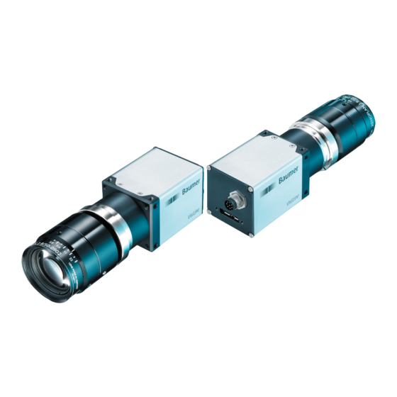
Camera Models ◄ Figure 1 Baumer VLU camera Full Sensor Camera Type Resolution Frames Size [max. fps] CCD Sensor (monochrome / color) VLU-02M / VLU-02C 1/4" 656 x 490 VLU-12M / VLU-12C 1/3" 1288 x 960 CMOS Sensor (monochrome / color) VLU-03M / VLU-03C 1/3"... -
Page 10: Installation
Installation Caution Observe precautions for handling electrostatically sensitive devices! Lens mounting Notice Ensure the sensor and lens are not contaminated with dust and airborne particles when mounting the support or the lens to the device! The following points are very important: ▪ Install the camera in an environment that is as dust free as possible! ▪... -
Page 11: Heat Transmission
6.2.2 Heat Transmission Caution Heat can damage the camera. Heat must be dissipated adequately to en- sure that the temperature does not exceed the values in the table below. As there are numerous possibilities for installation, Baumer do not specifiy a specific method for proper heat dissipation, but suggest the following principles: ▪ operate the cameras only in mounted condition ▪... -
Page 12: Pin Assignment
7. Pin Assignment 7.1 USB 3.0 Interface USB 3.0 Micro B 1 2 3 4 5 6 7 8 9 10 VBUS MicB_SSTX- MicB_SSTX+ GND_DRAIN MicB_SSRX- MicB_SSRX+ 7.2 Digital IOs Digital IOs (M8 / 8 pins / wire colors of the connecting cable) white grey IO Power VCC... -
Page 13: Led Signalling
7.2.1 LED Signalling ◄ Figure 3 LED position on Baumer VLU camera. Signal Meaning green USB 3.0 connection yellow USB 2.0 connection (settings possible, no frames) Notice Why can frames not be transferred over an USB 2.0 connection? The camera needs to be supplied with more than 2.5W when transferring frames. With an USB 2.0 connection maximally 2.5W are available. -
Page 14: Product Specifications
8. Product Specifications 8.1 Spectral Sensitivity for Baumer VLU Cameras The following graphs show the spectral sensitivity characteristics of monochrome and color matrix sensors for VLU cameras. The curves for the sensors do not take the char- acteristics of lenses and light sources without filters into account. Values relate to the respective technical data sheets for the sensors. -
Page 15: Field Of View Position
8.2 Field of View Position The figures and table below show the typical accuracy by assumption of the root mean square value: ± XM ± XR photosensitive surface of the sensor front cover glass thickness: 1 ± 0.1 mm cover glass of sensor thickness: D 14,6 ± Z optical path c mount (17.526 mm) Camera ±... -
Page 16: Acquisition Modes And Timings
(t ) is determined by the particular sensor and image format. readout Baumer cameras can be operated in three different modes, Free Running Mode, Fixed- Frame-Rate Mode and Trigger Mode. The cameras can be operated non-overlapped or overlapped, depending on the mode used and the combination of exposure and readout time:... -
Page 17: Fixed-Frame-Rate Mode
8.3.2 Fixed-Frame-Rate Mode With this feature, Baumer introduces a clever technique to the VLU camera series that enables the user to predefine a desired frame rate in continuous mode. For this mode, the cameras are equipped with an internal clock generator that creates trigger pulses. Notice Above a certain frame rate, skipping internal triggers becomes unavoidable. In general, this depends on the combination of the adjusted frame rate, exposure and readout times. -
Page 18: Trigger Mode
8.3.3 Trigger Mode Image acquisition begins after a specified external event (trigger) occurs. Depending on the interval of triggers used, the camera can operate either non-overlapped or overlapped in this mode. With regard to timings in the trigger mode, the following basic formulas need to be taken into consideration: Case Formula earliestpossibletrigger(n+1) - Page 19 8.3.3.2 Overlapped Operation: t > t exposure(n+2) exposure(n+1) If the exposure time (t ) is increased from the current acquisition to the next acquisi- exposure tion, the time the camera is unable to process occurring trigger signals (t ) is scaled notready down accordingly.
- Page 20 8.3.3.3 Overlapped Operation: t < t exposure(n+2) exposure(n+1) If the exposure time (t ) is decreased from the current acquisition to the next acquisi- exposure tion, the time the camera is unable to process occurring trigger signals (t ) is scaled notready up accordingly.
- Page 21 8.3.3.4 Non-overlapped Operation If the frequency of the trigger signal is set long enough that the image acquisitions (t exposure ) run successively, the camera operates non-overlapped. readout Trigger Timings: triggerdelay A - exposure time frame (n) effective exposure(n) exposure(n+1) B - image parameters Exposure frame (n) effective...
-
Page 22: Advanced Timings For Usb 3.0 Vision
If the camera is unable to process incoming trigger signals, meaning that the camera should be triggered within the interval t , these triggers are skipped. On Baumer VLU notready cameras, the user will be informed about this fact by way of the "TriggerSkipped" event. - Page 23 8.3.4.3 TriggerOverlapped This signal is active for as long as the sensor is exposed and read out at the same time, meaning that the camera is operated overlapped. Trigger exposure(n) exposure(n+1) Exposure readout(n) readout(n+1) Readout Event: TriggerOverlapped Trigger Overlapped Once a valid trigger signal occurs outside of a readout, the "TriggerOverlapped" signal changes to state low.
-
Page 24: Software
8.4.1 Baumer GAPI Baumer GAPI stands for Baumer “Generic Application Programming Interface”. With this API, Baumer provides an interface for optimal integration and control of Baumer cam- eras. It provides interfaces to several programming languages, such as C, C++ and the .NET™... -
Page 25: Camera Functionalities
9.1.1 Image Format A digital camera usually delivers image data in at least one format - the native resolution of the sensor. Baumer cameras are able to provide several image formats (depending on the type of camera). Compared with standard cameras, the image format on Baumer cameras includes not only the resolution, but also a set of predefined parameters. -
Page 26: Pixel Format
9.1.2 Pixel Format On Baumer digital cameras, the pixel format depends on the selected image format. 9.1.2.1 Definitions RAW: Raw data format. Here, the data is stored without being processed. Bayer: Raw data format of color sensors. Color filters are placed on these sensors in a checkerboard pattern, generally in a 50% green, 25% red and 25% blue array. - Page 27 For RGB or BGR these 8 bits per channel equate to 24 bits overall. Two bytes are needed to transmit more than 8 bits per pixel - even if the second byte is not completely filled with data. In order to save bandwidth, packed formats have been added to Baumer VLU cameras. In these for- mats, the unused bits of one pixel are filled with data from the next pixel. 8 bit: ◄ Figure 10...
-
Page 28: Exposure Time
Incidence of light causes charge separation on the semiconductors of the sensor. The signal strength is influenced by the incoming amount of photons. It can be increased by increasing the exposure time (t exposure On Baumer VLU cameras, the exposure time can be set within the following ranges (in- crements of 1μsec): Camera Type exposure exposure Monochrome VLU-02M 4 μsec... -
Page 29: Prnu / Dsnu Correction (Fpn - Fixed Pattern Noise)
9.1.4 PRNU / DSNU Correction (FPN - Fixed Pattern Noise) Camera Type CCD (monochrome / color) VLU-02M / VLU-02C □ VLU-12M / VLU12C □ CMOS (monochrome / color) VLU-03M / VLU-03C ■ CMOS sensors exhibit non-uniformities that are often called fixed pattern noise (FPN). However, it is not actually noise, but rather a fixed variation from pixel to pixel that can be corrected. The advantage of using this correction is a more homogeneous picture which may simplify image analysis. -
Page 30: Hdr (High Dynamic Range)
9.1.5 HDR (High Dynamic Range) Camera Type CCD (monochrome / color) VLU-02M / VLU-02C □ VLU-12M / VLU12C □ CMOS (monochrome / color) VLUC-03M / VLU-03C ■ Alongside the standard linear response, the sensor also supports a special high dynamic range mode (HDR) called piecewise linear response. -
Page 31: Look-Up-Table
γ Y' = Y original ▲ Figure 14 On Baumer VLU cameras the correction factor γ is adjustable from 0.001 to 2. Non-linear perception of the human eye. The values of the calculated intensities are entered into the Look-Up-Table (see 9.1.5). H - Perception of bright- Previously existing values within the LUT will be overwritten. -
Page 32: Region Of Interest (Roi)
9.1.8 Region of Interest (ROI) With the "Region of Interest" (ROI) function, you can predefine a so-called Region of Interest (ROI) or Partial Scan. This ROI is an area of pixels of the sensor. When an im- age is acquired, only the information about these pixels is transferred to the PC. Not all lines of the sensor are read out, which therefore decreases the readout time (t ). -
Page 33: Binning
By using this opera- tion, the progression in sensitivity is coupled with a reduction in resolution. Baumer cameras support three types of binning - vertical, horizontal and bidirectional. In unidirectional binning, vertically or horizontally neighboring pixels are aggregated and reported to the software as a single "superpixel". -
Page 34: Brightness Correction (Binning Correction)
9.1.10 Brightness Correction ( Binning Correction) Aggregation of charge carriers may cause an overload. Binning correction was introduced to prevent this. Here, three binning modes need to be considered separately: Binning Realization 1x2 binning is performed within the sensor, binning correction also takes place here. A possible overload is prevented by halving the exposure time. 2x1 binning takes place within the FPGA of the camera. -
Page 35: Flip Image
9.1.11 Flip Image The Flip Image function lets you flip the captured images horizontally and/or vertically before they are transmitted from the camera. Notice Any defined ROI will also be flipped. Camera Type VLU-02M / VLU-02C ■ □ VLU-12M / VLU-12C ■ □ VLU-03M / VLU-03C ■... -
Page 36: Color Processing
The white balance is used to sensitize the camera to the color temperature of the light at the pickup location. This feature is available on all color cameras in the Baumer VLU series, and takes place within the Bayer processor. -
Page 37: One Push White Balance
9.4 Analog Controls 9.4.1 Offset / Black Level CCD Sensor On Baumer VLU cameras with CCD sensors, the offset (or black level) is adjustable from 0 to 255 LSB (relating to 12 bit). Camera Type Increments of 1 LSB... -
Page 38: Gain
9.4.2 Gain In industrial environments, motion blur is unacceptable. Therefore, exposure times are limited. However, this causes low output signals from the camera and results in dark im- ages. To solve this issue, the signals can be amplified by a user-defined gain factor within the camera. This gain factor is adjustable. Notice Increasing the gain factor causes an increase in image noise. CCD Sensor Camera Type Gain factor [db]... -
Page 39: Pixel Correction
Pixel Correction 9.5.1 General information There is a certain probability of abnormal pixels - so-called defect pixels - occurring for sensors from all manufacturers. The charge quantity on these pixels is not linearly depen- dent on the exposure time. The occurrence of these defect pixels is unavoidable and intrinsic to the manufacturing and aging process of the sensors. -
Page 40: Correction Algorithm
Corrected Pixels 9.5.3 Defectpixellist As stated previously, this list is determined within the production process of Baumer cam- eras and stored in the factory settings. Additional hot or cold pixels can develop during the lifecycle of a camera. In this case, Baumer gives you the option to add their coordinates to the defectpixellist. -
Page 41: Process Interface
On the software side the input signals are named "Trigger", "Timer" and "LineOut 1..3". state selection signal selection (inverter) (software side) Trigger state high Timer (Input) Line 1 LineOut 1 (Output) LineOut 2 (Output) state low LineOut 3 (Output) ◄ Figure 30 IO matrix of the IO Matrix Baumer VLU on the in- put side. -
Page 42: Io Circuits
9.6.1.2 Configurable Outputs With this feature, Baumer offers the possibility of wiring the output connectors to internal signals, which are controlled on the software side. Hereby on VisiLine cameras, the output connector can be wired to one of provided inter- ®... -
Page 43: Trigger
Trigger (valid) trigger 4.5V delay trigger ▲ Figure 32 Trigger signal, valid for Exposure Baumer cameras. Readout ◄ Figure 33 Camera in trigger Time mode: A - Trigger delay B - Exposure time C - Readout time Different trigger sources can be used here. -
Page 44: Debouncer
9.6.5 Debouncer The basic idea behind this feature was to separate interfering signals (short peaks) from valid square wave signals, which can be important in industrial environments. Debouncing means that invalid signals are filtered out, and signals lasting longer than a user-defined testing time t will be recognized and routed to the camera to induce a trigger. DebounceHigh In order to detect the end of a valid signal and filter out possible jitters within the signal, ... -
Page 45: Timers
9.6.8 Frame counter The frame counter is part of the Baumer Image Info Header and is supplied with every im- age, if chunk mode is activated. It is generated by hardware and can be used to verify that each of the camera's images is transmitted to the PC and received in the right order. -
Page 46: Sequencer
Sequencer 9.7.1 General Information A sequencer is used for the automated control of series of images using different sets of parameters. Figure 36 ► Flow chart of sequencer. m - number of loop passes n - number of set repetitions o - number of sets of parameters z - number of frames per trigger... -
Page 47: Baumer Optronic Sequencer In Camera Xml-File
9.7.2 Baumer Optronic Sequencer in Camera xml-file “BOSequencer” The Baumer Optronic sequencer is described in the category by the fol- lowing features: <Category Name="BOSequencer" NameSpace="Custom"> <pFeature>BoSequencerEnable</pFeature> Enable / Disable <pFeature>BoSequencerStart</pFeature> Start / Stop <pFeature>BoSequencerRunOnce</pFeature> Run Once / Cycle <pFeature>BoSequencerFreeRun</pFeature> Free Running / Trigger <pFeature>BoSequencerSetSelector</pFeature>... -
Page 48: Capability Characteristics Of Baumer Gapi Sequencer Module
(A,B and C) from the previous example. The frame counter (z) is set to 2. This means the camera records two pictures after an incoming trigger signal. 9.7.4 Capability Characteristics of Baumer GAPI Sequencer Module ▪ up to 128 sets of parameters ▪... -
Page 49: Double Shutter
Trigger Flash Exposure Prevent Light ◄ Figure 40 Example of a double Readout shutter. On Baumer VLU cameras, this feature is realized within the sequencer. In order to generate this sequence, the sequencer must be configured as follows: Parameter Setting: Sequencer Run Mode Once by Trigger Sets of parameters (o) Loops (m) Repeats (n) -
Page 50: User Sets
9.9 User Sets Four user sets (0-3) are available for the Baumer cameras in the VLU series. User set 0 is the default set and contains the factory settings. User sets 1 to 3 are user-specific and can contain any user-definable parameters (see table below). These user sets are stored within the camera and can be loaded, saved and transferred to other cameras in the VLU series. -
Page 51: Factory Settings
9.10 Factory Settings The factory settings are stored in "user set 0", the default user set. This is the only user set that cannot be edited. 9.11 Timestamp The timestamp is part of the USB 3.0 Vision standard. It is 64 bits long and denoted in nanoseconds. -
Page 52: Interface Functionalities
10.1 Device Information This information on the device is part of the camera's USB descriptor. Included information: ▪ Product ID (PID) ▪ Vendor ID (VID) Model Name Baumer USB Vendor ID Baumer USB Product ID [Hexadecimal] [Hexadecimal] VLU-02M 2825 010A VLU-02C... -
Page 53: Baumer Image Info Header (Chunk)
10.2 Baumer Image Info Header (Chunk) The Baumer Image Info Header is a data packet that is generated by the camera and integrated into the Payload (every image), if chunk mode is activated. ◄ Figure 42 Location of the Baumer Image Info Header This integrated data packet contains different settings for the image. -
Page 54: Message Channel
10.3 Message Channel The asynchronous message channel is described in the USB 3.0 Vision standard and allows you to signal events. There is a timestamp (64 bits) for each announced event, which contains the accurate time at which the event occurred. Each event can be activated and deactivated separately. -
Page 55: Start-Stop Behaviour
If image acquisition is started before the interface is activated, the recorded images are lost. If the interface is stopped during a transmission, this is aborted immediately. 11.3 Acquisition Modes In general, three acquisition modes are available for the cameras in the Baumer VLU series. 11.3.1 Free Running Free running means the camera records images continuously without external events. -
Page 56: Cleaning
Cleaning Cover glass Notice The sensor is mounted dust-proof. Remove of the cover glass for cleaning is not neces- sary. Avoid cleaning the cover glass of the sensor glass if possible. To prevent dust, follow the instructions under "Install lens". If you must clean it, use compressed air or a soft, lint free cloth dampened with a small quantity of pure alcohol. -
Page 57: Warranty Notes
Warranty Notes Notice If it is obvious that the device is / was dismantled, reworked or repaired by anyone other than Baumer technicians, Baumer Optronic will not take any responsibility for the sub- sequent performance and quality of the device! Support If you have any problems with the camera, feel free to contact our support. - Page 58 Cameras of the Baumer VLU family comply with: ▪ ▪ RoHS 17.1 We declare, under our sole responsibility, that the previously described Baumer VLU cam- eras conform with the directives of the CE. 17.2 RoHS All VLU cameras comply with the recommendation of the European Union concerning...
- Page 60 Baumer Optronic GmbH Badstrasse 30 DE-01454 Radeberg, Germany Phone +49 (0)3528 4386 0 · Fax +49 (0)3528 4386 86 sales@baumeroptronic.com · www.baumer.com...
Need help?
Do you have a question about the USB3 Vision and is the answer not in the manual?
Questions and answers