
Related Manuals for Baumer SXC10


Summary of Contents for Baumer SXC10
- Page 1 Baumer SXC v1 User's Guide for CameraLink Cameras with Truesense Imaging ® Sensors...
-
Page 3: Table Of Contents
5.1. SXC – Cameras with C-Mount ................8 5.2. SXC-F – Cameras with F-Mount ................9 6. Product Specifications ..................10 6.1. Sensor Specifications ..................10 6.1.1. Quantum Efficiency for Baumer SXC Cameras ..........10 6.1.2. Shutter ......................10 6.1.3. Readout Modes ....................11 6.2. Timings ......................... 13 6.2.1. - Page 4 8.2.1. User-specific Color Adjustment ..............30 8.2.2. One Push White Balance ................30 8.3. Analog Controls ....................31 8.3.1. Black Level ....................31 8.3.2. Gain ....................... 31 8.4. Pixel Correction ....................32 8.4.1. General information ..................32 8.4.2. Correction Algorithm ..................32 8.4.3. Defectpixellist ....................33 8.5. Process Interface ....................33 8.5.1. ...
-
Page 6: General Information
General Information Read these manual carefully and observe the notes and safety instruc- tions! Thank you for purchase a camera of the Baumer family. This User´s Guide describes how to connect, set up and use the camera. Keep the User´s guide store in a safe place and transmit them to the eventually following users. Please also note the provided technical data sheet. Target group for this User´s Guide This User's Guide is aimed at experienced business users, which want to integrate ... -
Page 7: General Safety Instructions
General safety instructions Observe the the following safety instructions when using the camera to avoid any damage or injuries. Caution Provide adequate dissipation of heat, to ensure that the temperature does not exceed +60°C (+140°F). The surface of the camera may be hot during operation and immediately after use. Be careful when handling the camera and avoid contact over a longer period. Caution A power supply with electrical isolation is required for proper operation of the camera. Otherwise the device may be damaged! Intended Use The camera is used to capture images that can be transferred over one CameraLink ®... -
Page 8: Camera Models
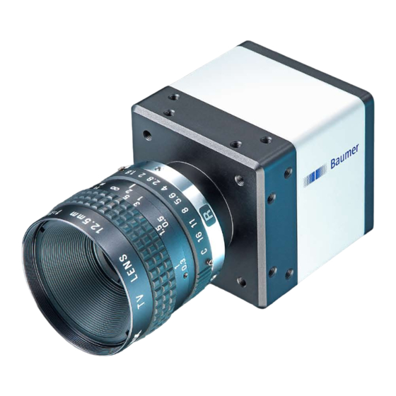
SXC – Cameras with C-Mount Figure 1 ► Front and rear view of a Baumer SXC camera. Full Sensor Camera Type Resolution Frames Size [max. fps] Monochrome SXC10 1/2" 1024 x 1024 SXC20 2/3" 1600 x 1200 SXC21 2/3" 1920 x 1080 SXC40 1" 2336 x 1752 SXC80 4/3"... -
Page 9: Sxc-F - Cameras With F-Mount
5.2. SXC-F – Cameras with F-Mount ◄ Figure 3 Front view of a Baumer SXC-F camera. Full Sensor Camera Type Resolution Frames Size [max. fps] Monochrome SXC21-F 2/3" 1920 x 1080 SXC40-F 1" 2336 x 1752 SXC80-F 4/3" 3296 x 2472 Color SXC21c-F 2/3" 1920 x 1080 SXC40c-F 1"... -
Page 10: Product Specifications
Product Specifications 6.1. Sensor Specifications 6.1.1. Quantum Efficiency for Baumer SXC Cameras The quantum efficiency characteristics of monochrome and color matrix sensors for Baumer SXC cameras are displayed in the following graphs. The characteristic curves for the sensors do not take the characteristics of lenses and light sources without filters into consideration, but are measured with an AR coated cover glass. Values relating to the respective technical data sheets of the sensors manufacturer. -
Page 11: Readout Modes
6.1.3. Readout Modes The Truesense Imaging sensors, employed in Baumer SXC cameras, are subdivided into four Taps. ◄ Figure 7 Taps of the employed sensors. Due to Baumer's integrated calibration technique, these taps are invisible within the re- corded images, but affect the operation and the rate of the readout process and therewith the readout time (t readout 6.1.3.1. Quad Mode On quad readout mode all four taps are read out simultaneously as displayed in the sub- sequent figure. ◄ Figure 8 Quad Tap Readout Mode. - Page 12 6.1.3.3. Single Mode In single readout mode all taps are combined as displayed in the subsequent figure. Figure 10 ► Single Tap Readout Mode. The data of all pixels of the sensor are moved to the output register and afterwards trans- fered to the memory. Once the information have left the output register, the readout is done. Due to the fact, that the complete sensor needs to be read out, the readout time t readout increased compared to quad and dual readout mode.
-
Page 13: Timings
) can be adjusted by the user, however, the time need- exposure ed for the readout (t ) is given by the particular sensor and image format. readout Baumer cameras can be operated with two modes, the Free Running Mode and the Trigger Mode. The cameras can be operated non-overlapped or overlapped. Depending on the mode used, and the combination of exposure and readout time: Non-overlapped Operation... -
Page 14: Trigger Mode
6.2.2. Trigger Mode After a specified external event (trigger) has occurred, image acquisition is started. De- pending on the interval of triggers used, the camera operates non-overlapped or over- lapped in this mode. With regard to timings in the trigger mode, the following basic formulas need to be taken into consideration: Case Formula earliestpossibletrigger(n+1) readout(n) exposure(n+1) - Page 15 6.2.2.2. Overlapped Operation: t > t exposure(n+2) exposure(n+1) If the exposure time (t ) is increased form the current acquisition to the next acquisi- exposure tion, the time the camera is unable to process occuring trigger signals (t ) is scaled notready down. This can be simulated with the formulas mentioned above (no. 2 or 4, as is the case). Trigger triggerdelay exposure(n) exposure(n+1) exposure(n+2) Exposure Timings: A - exposure time frame (n) effective B - image parameters readout(n)
- Page 16 6.2.2.3. Overlapped Operation: t < t exposure(n+2) exposure(n+1) If the exposure time (t ) is decreased from the current acquisition to the next acquisi- exposure tion, the time the camera is unable to process occuring trigger signals (t ) is scaled notready When decreasing the t such, that t exceeds the pause between two incoming exposure notready trigger signals, the camera is unable to process this trigger and the acquisition of the im-...
- Page 17 6.2.2.4. Non-overlapped Operation If the frequency of the trigger signal is selected for long enough, so that the image acquisi- tions (t ) run successively, the camera operates non-overlapped. exposure readout Trigger triggerdelay exposure(n) exposure(n+1) Exposure Timings: A - exposure time frame (n) effective B - image parameters frame (n) effective readout(n) readout(n+1) Readout C - exposure time frame (n+1) effective D - image parameters frame (n+1) effective E - earliest possible trigger notready...
-
Page 18: Field Of View Position
6.3. Field of View Position The typical accuracy by assumption of the root mean square value is displayed in the figures and the table below: ±x Photosensitive surface of the sensor Figure 11 ► Sensor accuracy of Baumer SXC cameras. Camera ± x ± y ± x ± y ± β ± z ± z... -
Page 19: Process- And Data Interface
Power V white Line 9 blue brown Line 1 black green Line 0 yellow grey pink Line 7 blue Line 8 Line 2 6.4.3. LED Signaling ◄ Figure 7 LED positions on Baumer SXC cameras. Signal Meaning green Power on yellow Readout active green Transmitting red (yellow in both) Configuration command processing... -
Page 20: Environmental Requirements
Provide adequate dissipation of heat, to ensure that the temperature does not exceed +60°C (+140°F). The surface of the camera may be hot during operation and immediately after use. Be careful when handling the camera and avoid contact over a longer period. Humidity Storage and Operating Humidity 10% ... 90% Non-condensing Figure 12 ► Temperature measure- ment points of Baumer SXC cameras. 6.5.2. Heat Transmission It is very important to provide adequate dissipation of heat, to ensure that the housing temperature does not reach or exceed +60°C (+140°F). As there are numerous possibili- ties for installation, Baumer do not specifiy a specific method for proper heat dissipation, but suggest the following principles: ▪ operate the cameras only in mounted condition ▪ mounting in combination with forced convection may provide proper heat dissipation Please refer to the respective data sheet. -
Page 21: Mechanical Tests
6.5.3. Mechanical Tests Environmental Standard Parameter Testing Vibration, sinu- IEC 60068-2-6 Search for Reso- 10-2000 Hz sodial nance Amplitude under- 1.5 mm neath crossover frequencies Acceleration Test duration 15 min Vibration, IEC 60068- Frequency range 20-1000 Hz broad band 2-64 Acceleration 10 g Displacement 5.7 mm... -
Page 22: Software
, as well as Mono on Linux operating systems, which offers the ® ® use of other languages, such as e.g. C# or VB.NET. Notice There is currently no Baumer GAPI version for Linux available with support for CameraLink ® Notice Please note the extra instructions to the software Baumer GAPI. Specifically for CameraLink Cameras, the "User´s Guide CLConfig Tool". -
Page 23: Camera Functionalities
Camera Functionalities 8.1. Image Acquisition 8.1.1. Image Format A digital camera usually delivers image data in at least one format - the native resolution of the sensor. Baumer cameras are able to provide several image formats (depending on the type of camera). Compared with standard cameras, the image format on Baumer cameras not only in- cludes resolution, but a set of predefined parameter. These parameters are: ▪ Resolution (horizontal and vertical dimensions in pixels) ▪ Binning Mode (see chapter 4.1.7) Camera Type Monochrome SXC10 ■ ■ ■ ■ SXC20 ■... -
Page 24: Pixel Format
8.1.2. Pixel Format On Baumer digital cameras the pixel format depends on the selected image format. 8.1.2.1. Definitions RAW: Raw data format. Here the data are stored without processing. Bayer: Raw data format of color sensors. Color filters are placed on these sensors in a checkerboard pattern, generally in a 50% green, 25% red and 25% blue array. Figure 13 ► Sensor with Bayer Pattern. Mono: Monochrome. The color range of mono images consists of shades of a single color. In general, shades of gray or black-and-white are synonyms for mono-... - Page 25 ◄ Figure 16 Spreading of Mono 10 Byte 1 Byte 2 bit over 2 bytes. 12 bit: unused bits ◄ Figure 17 Spreading of Mono 12 bit over two bytes. Byte 1 Byte 2 8.1.2.2. Pixel Formats on Baumer SXC Cameras Camera Type Monochrome SXC10 ■ ■ ■ □ □ □ SXC20 ■ ■...
-
Page 26: Exposure Time
Pixel Figure 18 ► Incidence of light causes charge separation on the semiconductors of the sensor. The signal strength is influenced by the incoming amount of photons. It can be increased by increasing the exposure time (t exposure On Baumer SXC cameras, the exposure time can be set within the following ranges (step size 1μsec): Camera Type exposure exposure Monochrome SXC10 4 μsec 1 sec SXC20 5 μsec... -
Page 27: Look-Up-Table
8.1.4. Look-Up-Table The Look-Up-Table (LUT) is employed on Baumer monochrome cameras. It contains 2 (4096) values for the available levels of gray. These values can be adjusted by the user. 8.1.5. Region of Interest (ROI) With the ROI function it is possible to predefine a so-called Region of Interest (ROI). This ROI is an area of pixels of the sensor. On image acquisition, only the information of these pixels is sent to the PC. Therefore all the lines of the sensor need not be read out, which decreases the readout time (t ). This increases the frame rate. readout This function is employed, when only a region of the field of view is of interest. It is coupled to a reduction in resolution. - Page 28 Pixel Information of Interrest Read out Lines Discarted Pixel Information Figure 21 ► Partial Scan: Read out Lines. The most significant reduction of the readout time – compared to a full frame readout in dual mode – can be achieved if the ROI is positioned as follows: ▪ within one of the sensor halves ▪ symmetrically spread to both sensor halves For example, the readout time of the ROI's in the figures 21 and 22 is the same. Figure 22 ► Partial Scan: Example ROI's with identical readout times. On asymmetrically spread ROI's, the readout time is affected by the bigger part of the ROI. An example for this fact is shown in the figure below: Figure 23 ► Partial Scan: Read out time linked with position of the ROI.
-
Page 29: Binning
On digital cameras, you can find several operations for progressing sensitivity. One of them is the so-called "Binning". Here, the charge carriers of neighboring pixels are aggre- gated. Thus, the progression is greatly increased by the amount of binned pixels. By using this operation, the progression in sensitivity is coupled to a reduction in resolution. Baumer cameras support three types of Binning - vertical, horizontal and bidirectional. In unidirectional binning, vertically or horizontally neighboring pixels are aggregated and reported to the software as one single "superpixel". In bidirectional binning, a square of neighboring pixels is aggregated. -
Page 30: Brightness Correction (Binning Correction)
Aggregation of charge carriers from four pixels Charge quantity Super pixel in bidirectional binning. 8.2. Color Adjustment – White Balance This feature is available on all color cameras of the Baumer SXC series and takes place within the Bayer processor. White balance means independent adjustment of the three color channels, red, green and blue by employing of a correction factor for each channel. 8.2.1. User-specific Color Adjustment The user-specific color adjustment in Baumer color cameras facilitates adjustment of the ... -
Page 31: Analog Controls
8.3. Analog Controls 8.3.1. Black Level On Baumer cameras, the offset (or black level) is adjustable from 0 to 16 LSB (relating to 8 bit). Camera Type Step Size 1 LSB Relating to Monochrome SXC10 14 bit SXC20 14 bit SXC21 14 bit SXC40 14 bit SXC80 14 bit Color SXC10c 14 bit SXC20c 14 bit SXC21c 14 bit SXC40c... -
Page 32: Pixel Correction
Charge quantity „Cold Pixel“ Figure 33 ► Charge quantity of "hot" and "cold" pixels com- pared with "normal" pixels. 8.4.2. Correction Algorithm On monochrome cameras of the Baumer SXC series, the problem of defect pixels is solved as follows: ▪ Possible defect pixels are identified during the production process of the camera. ▪ The coordinates of these pixels are stored in the factory settings of the camera (see 4.4.3. Defectpixellist). ▪ Once the sensor readout is completed, correction takes place: ▪ Before any other processing, the values of the neighboring pixels on the left and the ... -
Page 33: Defectpixellist
On the software side the input signals are named "Line0", "Line1" and "Line2". state selection (software side) state high (Input) Line0 Line0 state low state high (Input) Line1 Line1 state low state high (Input) Line2 Line2 ◄ Figure 35 state low IO matrix of the Baumer SXC on input IO Matrix side. - Page 34 (software side) (software side) state high (Output) Line 7 state low state high (Output) Line 8 FrameGrabberLine3 state low state high (Output) Line 9 state low IO Matrix Figure 36 ► IO matrix of the Baumer SXC on output side.
-
Page 35: Trigger Input
8.5.2. Trigger Input Trigger signals are used to synchronize the camera exposure and a machine cycle or, in case of a software trigger, to take images at predefined time intervals. Trigger (valid) high 4.5V Exposure Figure 37 ▲ Trigger signal, valid for Baumer cameras. Readout Time ◄ Figure 38 Camera in trigger Different trigger sources can be used here. mode: A - Trigger delay B - Exposure time 8.5.3. Trigger Source C - Readout time... -
Page 36: Debouncer
DebounceHigh user defined debouncer delay for state low Principle of the Baumer DebounceLow debouncer. 8.5.5. Flash Signal The CameraLink standard doesn't describe an explicite flash signal. ® On Baumer cameras, this feature is realized by the internal signal "ExposureActive", which can be wired to one of the digital outputs. -
Page 37: User Sets
User Sets 8.6. Three user sets (1-3) are available for the Baumer cameras of the SXC series. The user sets can contain the following information: Parameter Parameter Binning Mode Mirroring Control CameraLink Control Offset ® Defectpixellist Partial Scan Digital I/O Settings Pixelformat Exposure Time Readout Mode Gain Factor Testpattern Look-Up-Table Trigger Settings These user sets are stored within the camera and and cannot be saved outside the de- vice. -
Page 38: Cameralink
CameraLink ® The CameraLink interface was especially developed for cameras in machine vision ap- ® plications and provides high transfer rates and low latency. Depending on the configura- tion (Base, Medium or Full) the transfer rate adds up to 680 MBytes/sec. Cameras of the Baumer SXC series are equipped with a CameraLink Base interface and ® therewith able to transmit up to 240MBytes/sec. 9.1. Channel Link and LVDS Technology CameraLink bases upon the Channel Link technology, but provides a specification, that ® ® is more beneficial for machine vision. Channel Link in turn is an advancement of the LDVS (Low Voltage Differential Signaling) ® standard – a low power, high speed interface standard. -
Page 39: Camera Control
▪ no handshaking. 9.2.2. Camera Control According to the CameraLink standard four LVDS pairs have to be reserved for general- ® purpose camera control. They are defined as frame grabber outputs and camera inputs. The definition of these signals is left to the camera manufacturer. Signal Baumer Naming Employment Camera Control 1 (CC1) FrameGrabberLine0 Camera Control 2 (CC2) FrameGrabberLine1 On Baumer SXC cameras, the wiring of these signals is arbitrary. Camera Control 3 (CC3) FrameGrabberLine2 Camera Control 4 (CC4) FrameGrabberLine3 9.2.3. Video Data The standard designates four signals (as well as the signal state) for the validation of ... -
Page 40: Cameralink ® Taps
9.4. CameraLink Taps ® The standard defines a tap as "the data path carrying a stream of pixels". This means the number of taps equates to the number of simultaniously transferred pixel. Notice Please do not mix up sensor taps and CameraLink taps. ® 9.4.1. Tap Configuration Within the subsequent sections, the transmission of images with different pixel formats (bit depth) linked to the employment of different numbers of taps is displayed. 9.4.1.1. 8-bit Monochrome Single Tap Transmission Tap 1 Tap 1 Tap 1 Tap 1... - Page 41 9.4.1.5. 10-bit Monochrome Single Tap Transmission Tap 1 Tap 1 Tap 1 Tap 1 Tap 1 Tap 1 Tap 1 Tap 1 Port A bit 0 bit 1 bit 2 bit 3 bit 4 bit 5 bit 6 bit 7 Tap 1 Tap 1 Port B...
-
Page 42: Tap Geometry
"on-the-fly", the CameraLink standards demands the specification of the used / sup- ® ported tap geometries from the manufacturers of both, cameras and frame grabbers. 9.4.2.1. Single Tap Geometry For single tap transmission the cameras of the Baumer SXC series employ the 1X-1Y tap geometry: Figure 42 ► Tap geometry 1X-1Y. The pixel information is transmitted pixel-by- pixel and line-by-line. -
Page 43: Cleaning
Cleaning Cover glass Notice The sensor is mounted dust-proof. Remove of the cover glass for cleaning is not neces- sary. Avoid cleaning the cover glass of the CCD sensor if possible. To prevent dust, follow the instructions under "Install lens". If you must clean it, use compressed air or a soft, lint free cloth dampened with a small ... -
Page 44: Disposal
Keep the original packaging during the warranty period in order to be able to pack the device properly in the event of a warranty claim. Warranty Notes Notice If it is obvious that the device is / was dismantled, reworked or repaired by other than Baumer technicians, Baumer Optronic will not take any responsibility for the subse- quent performance and quality of the device! Lens Mounting Notice Avoid contamination of the sensor and the lens by dust and airborne particles when mounting a lens to the device! Therefore the following points are very important:... -
Page 45: Support
▪ FCC Part 15 Class B, ▪ RoHS 15.1. We declare, under our sole responsibility, that the previously described Baumer SXC cameras conform with the directives of the CE. 15.2. FCC – Class B Device : This equipment has been tested and found to comply with the limits for a Class B digital device, pursuant to part 15 of the FCC Rules. These limits are designed to pro- vide reasonable protection against harmful interference in a residential environment. - Page 46 Support If you have any problems with the camera, then feel free to contact our support. Worldwide Baumer Optronic GmbH Badstrasse 30 DE-01454 Radeberg, Germany Tel: +49 (0)3528 4386 845 Mail: support.cameras@baumer.com Website: www.baumer.com...
- Page 48 Baumer Optronic GmbH Baumer Optronic GmbH Badstrasse 30 DE-01454 Radeberg, Germany Phone +49 (0)3528 4386 0 · Fax +49 (0)3528 4386 86 sales@baumeroptronic.com · www.baumer.com DE-01454 Radeberg, Germany Phone +49 (0)3528 4386 0 · Fax +49 (0)3528 4386 86 sales@baumeroptronic.com · www.baumeroptronic.com...
Need help?
Do you have a question about the SXC10 and is the answer not in the manual?
Questions and answers