
Related Manuals for Baumer VLXT


Summary of Contents for Baumer VLXT
- Page 1 Operating Manual VLXT(.I) (.EF) (.JP) / VLXT.FO cameras (10 Gigabit Ethernet) VLXN.I.JP cameras EN-US (5 Gigabit Ethernet)
-
Page 2: Table Of Contents
4.7 Cables ........................38 4.8 Cleaning ........................ 39 5. Pin Assignment / LED-Signaling ................40 5.1 VLXT(.I) (.EF) (.JP) (10GBASE-T) / VLXN.I.JP (5GBASE-T) ....... 40 5.1.1 Data Interface ....................40 5.1.2 Power and Process Interface ................. 40 5.1.3 UART0 Interface (≥ Release 3 only) ............... 41 5.1.4 Digital-IO...................... - Page 3 7.1.1 AcquisitionAbort ....................55 7.1.2 AcquisitionFrameCount .................. 55 7.1.3 AcquisitionFrameRate ..................55 7.1.4 AcquisitionFrameRateEnable ................. 56 7.1.5 AcquisitionMode ..................... 56 7.1.6 AcquisitionStart ....................57 7.1.7 AcquisitionStatus .................... 57 7.1.8 AcquisitionStatusSelector ................57 7.1.9 AcquisitionStop ....................58 7.1.10 ExposureAuto (≥ Release 2 only) ..............58 7.1.11 ExposureMode ....................
- Page 4 7.6.5 ColorTransformationResetToFactoryList ............83 7.6.6 ColorTransformationValue ................84 7.6.7 ColorTransformationValueSelector ..............84 7.7 Category: CounterAndTimerControl ..............84 7.7.1 CounterDuration ..................... 84 7.7.2 CounterEventActivation .................. 85 7.7.3 CounterEventSource ..................85 7.7.4 CounterReset ....................85 7.7.5 CounterResetActivation .................. 86 7.7.6 CounterResetSource ..................86 7.7.7 CounterSelector .....................
- Page 5 7.9.40 DeviceVersion .................... 102 7.9.41 ReadOutTime ..................... 102 7.9.42 TimestampLatch ..................103 7.9.43 TimestampLatchValue ................103 7.9.44 TimestampLatchValuePtpDays (≥ Release 2 only) ........103 7.9.45 TimestampLatchValuePtpHours (≥ Release 2 only) ........103 7.9.46 TimestampLatchValuePtpMinutes (≥ Release 2 only) ........ 104 7.9.47 TimestampLatchValuePtpSeconds (≥ Release 2 only) ....... 104 7.9.48 TimestampLatchValuePtpNanoseconds (≥ Release 2 only) ....... 104 7.9.49 TimestampReset..................104 7.10 Category: DigitalIOControl ................105 7.10.1 LineDebouncerHighTimeAbs ..............
- Page 6 7.13.6 DecimationHorizontal ................. 141 7.13.7 DecimationHorizontalMode ................ 141 7.13.8 DecimationVertical ..................142 7.13.9 DecimationVerticalMode ................142 7.13.10 Height ....................... 142 7.13.11 HeightMax ....................144 7.13.12 ImageCompressionBitRate (VLXN only) ..........145 7.13.13 ImageCompressionJPEGFormatOption (.JP cameras only) ....145 7.13.14 ImageCompressionMode (.JP cameras only) .......... 146 7.13.15 ImageCompressionQuality (.JP cameras only) ........
- Page 7 7.17.13 OpticControllerFirmwareVersion .............. 173 7.17.14 OpticControllerInitialize ................174 7.17.15 OpticControllerModelName (except .EF) ..........174 7.17.16 OpticControllerSelector ................174 7.17.17 OpticControllerSerialNumber (except .EF) ..........174 7.17.18 OpticControllerStatus ................175 7.17.19 OpticControllerTemperature (except .EF) ..........175 7.17.20 OpticControllerThermalCompensation (except .EF) ........ 175 7.17.21 OpticControllerVendorName ..............
- Page 8 7.20.2.32 GevSCPHostPort ................194 7.20.2.33 GevSCPInterfaceIndex ..............194 7.20.2.34 GevSCPSDoNotFragment ..............194 7.20.2.35 GevSCPSFireTestPacket ..............194 7.20.2.36 GevSCPSPacketSize................ 195 7.20.2.37 GevSCSP ..................195 7.20.2.38 GevSecondURL ................195 7.20.2.39 GevStreamChannelSelector ............. 195 7.20.2.40 GevSupportedOption ................ 196 7.20.2.41 GevSupportedOptionSelector ............196 7.20.2.42 InterfaceSpeedMode................. 197 7.20.3 PayloadSize ....................
- Page 9 8.4.1 Time Saving in Multi-Camera Operation ............217 8.4.2 Configuration Example ................. 218 8.5 Multicast ......................220 8.6 IP Configuration ....................221 8.6.1 Persistent IP ....................221 8.6.2 DHCP (Dynamic Host Configuration Protocol) ..........221 8.6.3 LLA ....................... 222 8.6.4 Force IP ......................222 8.7 Packet Resend ....................223 8.7.1 Normal Case....................
-
Page 10: General Information
1. General Information Thanks for purchasing a camera of the Baumer family. This User´s Guide describes how to connect, set up and use the camera. Read this manual carefully and observe the notes and safety instructions! Support In case of any questions please contact our Technical & Application Support Center. - Page 11 Warranty Notes If it is obvious that the device is / was dismantled, reworked or repaired by other than Baumer technicians, Baumer Optronic will not take any responsibility for the subsequent performance and quality of the device! Copyright Any duplication or reprinting of this documentation, in whole or in part, and the reproduc- tion of the illustrations even in modified form is permitted only with the written approval of ...
-
Page 12: Software Licensing Information
1.1 Software Licensing Information The software in the camera includes the LWIP TCP/IP implementation. The copyright information for this implementation is as follows: Copyright (c) 2001, 2002 Swedish Institute of Computer Science. All rights reserved. Redistribution and use in source and binary forms, with or without modification, are per- mitted provided that the following conditions are met: 1. - Page 13 Copyright (c) 2009-2010 George V. Neville-Neil, Steven Kreuzer, Martin Burnicki, Jan Breuer, Gael Mace, Alexandre Van Kempen. Copyright (c) 2005-2008 Kendall Correll, Aidan Williams All Rights Reserved Redistribution and use in source and binary forms, with or without modification, are per- mitted provided that the following conditions are met: 1. Redistributions of source code must retain the above copyright notice this list of con- ditions and the following disclaimer.
-
Page 14: General Safety Instructions
Heat can damage the camera. Provide adequate dissipation of heat, to ensure that the temperature does not exceed the value (see Heat Trans- mission). As there are numerous possibilities for installation, Baumer recommends no specific method for proper heat dissipation, but suggest the following principle: ▪... -
Page 15: Camera Models
▪ Flexible generic programming interface (Baumer GAPI) for all Baumer integration cameras ▪ Powerful Software Development Kit (SDK) with sample codes and help files for simple integration ▪ Baumer Camera Explorer (Baumer GAPI Test Tool) for testing all camera functions ▪ GenICam™ compliant XML file to describe the camera functions ▪ Camera parameter programmable in real-time Reliable ▪... - Page 16 Identification of Release version • Label on camera • Baumer GAPI Camera Explorer / Category: Device Control → Feature: Device Ver- sion Release Version .JP Cameras ↔ Release Version Standard Cameras The release versions for .JP cameras are counted separately. However, the range of func- tions partly corresponds to the standard cameras, except for the special JP features. A comparison of the release versions is shown in the following table.
-
Page 17: Vlxt (.I) (.Ef) (.Jp) (10Gbase-T)
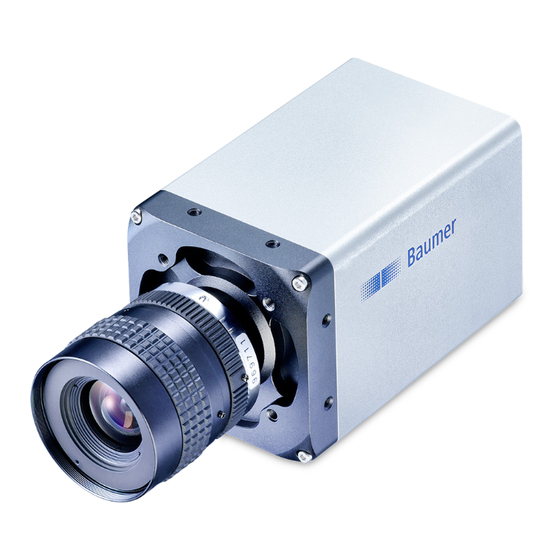
3.1 VLXT (.I) (.EF) (.JP) (10GBASE-T) No. Description No. Description Lens mount Ethernet Port (C- / M58- / TFL- / EF-Mount) UART0 Interface Camera LED (≥ Release 3, C- / EF-Mount only) 4 x Tube Adapter / front mounting threads GigE LED (except M58-mount, EF-mount) Power- and process interface... - Page 18 Full Sensor Camera Type Resolution Frames Size [max. fps] Color VLXT-06C.I.JP 1/1.7" 800 × 620 1578 8751 ׀ VLXT-31C.I (.JP) 1/1.8" 2048 × 1536 215 512 ׀ VLXT-50C.I 2/3" 2448 × 2048 163 361 ׀ VLXT-55C.I 1/1.8" 2464 × 2048 259 342 ׀ VLXT-71C.I 1.1" 3200 × 2200 174 471 ׀...
- Page 19 Dimensions (M58-mount) 92,2 8,33 10 x M3 x 5/7 temperature M58 x 0,75 60 ±0,2 measurement point 28,5 15,7 Pixel 0,0 12,9 103,82 ±0,4 Dimensions (TFL-mount) 8,33 10 x M3 x 5/7 1/4"-20 UNC x 6/9 7,83 temperature 60 ±0,2 measurement point Pixel 0,0 28,5...
- Page 20 Dimensions (EF-mount) 92,2 40,6 10 x M3 x 5/7 temperature 60 ±0,2 measurement point 72,5 28,5 15,7 Pixel 0,0 Canon EF-S Mount 12,9 113,82 136,1 V2.6 | 8/30/2022 | 1120758...
-
Page 21: Vlxn.i.jp (5Gbase-T)
3.2 VLXN.I.JP (5GBASE-T) No. Description No. Description Lens mount (M58-Mount) Camera LED Power- and process interface GigE LED Ethernet Port Full Sensor Camera Type Resolution Frames Size [max. fps] Monochrome VLXN-650M.I.JP 2.3" 9344 × 7000 11 9 ׀ image acquisition in the camera´s internal memory ׀interface (5 GigE) V2.6 | 8/30/2022 | 1120758... - Page 22 Dimensions (M58-mount) 92,2 8,33 10 x M3 x 5/7 temperature M58 x 0,75 60 ±0,2 measurement point 28,5 15,7 Pixel 0,0 12,9 103,82 ±0,4 V2.6 | 8/30/2022 | 1120758...
-
Page 23: Vlxt.fo (10Gbase-Sr/Lr)
3.3 VLXT.FO (10GBASE-SR/LR) No. Description No. Description Lens mount (C-mount) GigE LED UART0 Interface Camera LED (≥ Release 3, C- / EF-Mount only) 4 x Tube Adapter / front mounting threads SFP+ Socket Power- and process interface (including UART1 / RS232) Full Sensor Camera Type Resolution... - Page 24 Dimensions 68,5 8,33 1/4"-20 UNC x 6/9 M3 x 5/7 7,83 temperature measurement point 15,7 Pixel 0,0 15,7 12,9 8,33 M3 x 6/8 C-Mount M3 x 5/7 79,6 ±0,3 V2.6 | 8/30/2022 | 1120758...
-
Page 25: Installation
Provide adequate dissipation of heat, to ensure that the temperatures does not exceed the specified values. Baumer recommends the following methods for proper heat dissipation: ▪ Every form of convection around the device and mounting helps reduce temperature. Prevent heat from becoming trapped! ▪... - Page 26 Max. Temperature Measure Point Refer to the following tables for the maximum permissible temperature at the temperature measurement point. VLXT(N).I (.JP) VLXT.FO VLXT(.I) (.EF) (.JP) max. Temperature Camera Type (T = Measurement Point) Monochrome VLXT-06M.I / (.JP) 60 °C (140 °F) / 62 °C (143.6 °F) VLXT-17M.I...
- Page 27 VLXT.FO max. Temperature Camera Type (T = Measurement Point) Monochrome VLXT-31M.FO 65 °C (149 °F) VLXT-50M.FO 65 °C (149 °F) VLXT-90M.FO 65 °C (149 °F) VLXT-123M.FO 65 °C (149 °F) Color VLXT-50C.FO 65 °C (149 °F) VLXN max. Temperature Camera Type...
-
Page 28: Emergency Shutdown At Overtemperature
4.2.1 Emergency shutdown at Overtemperature To prevent damage on the hardware due to high temperatures, the camera is equipped with an emergency shutdown. The DeviceTemperatureStatusTransitionSelector (Catego- ry: Device Control) feature allows you to select different thresholds for temperatures: NormalToHigh: freely programmable value HighToExeeded: fixed value (image recording is stopped if exceeded) ExeededToNormal: freely programmable value, temperature for error-free re-ac- tivation of the camera. - Page 29 DeviceTemperatureEx- ceeded feature is set to True, the image recording is stopped, and the Camera LED is set to orange. VLXT(.I) (.EF) (.JP) Temperatures for emergency shutdown Camera Type (at internal temperature sensor) Monochrome VLXT-06M.I / (.JP)
-
Page 30: Mechanical Tests
VLXN Temperatures for emergency shutdown Camera Type (at internal temperature sensor) Monochrome VLXN-650M.I.JP 69 °C (156.2 °F) 4.3 Mechanical Tests except .EF cameras Environmental Standard Parameter Testing Vibration, IEC 60068-2-6 Continuous 10-2000 Hz sinussodial oscillation Amplitude un- 0,75 mm derneath cross- over frequencies Acceleration Test duration... -
Page 31: Lens Mounting
4.4 Lens mounting Notice Avoid contamination of the sensor and the lens by dust and airborne particles when mounting the lens to the device! Therefore the following points are very important: ▪ Install the camera in an environment that is as dust free as possible! ▪... -
Page 32: Modular Tube Systems (Ordered Separately)
4.5 Modular tube systems (ordered separately) 4.5.1 Tube Adapter M62 The peak torque while tightening the Camera screws is 0.9 Nm. Use a torque wrench! Tube Adapter Recommended grease for easier installation of the sealing rings: ELKALUB GLS 867 Distance Ring Tube Dimensions M62 5,25... - Page 33 Tube M62 M 62 54,5 Art. No.: 11185374 / Cover glass: PMMA (Acryl) Art. No.: 11195426 / Cover glass: restistant laminated safety cover glass Inner dimensions of the Tube M62 V2.6 | 8/30/2022 | 1120758...
-
Page 34: Tube Adapter M92
4.5.2 Tube Adapter M92 The peak torque while tightening the screws is 0.9 Nm. Use a torque wrench! Recommended grease for easier installation of the sealing rings: ELKALUB GLS 867 Holding Plate Camera Tube Adapter Distance Ring Tube Dimensions V2.6 | 8/30/2022 | 1120758... - Page 35 Distance Rings M 92 O-Ring Art. No.: 11704395 7.25 O-Ring Art. No.: 11704397 7.25 O-Ring Art. No.: 11704394 Tube M92 M 92 66.5 Art. No.: 11704312 / Cover glass: PMMA (Acryl) V2.6 | 8/30/2022 | 1120758...
-
Page 36: Ip Protection Classes
▪ The M12 connectors need to be tightened with a torque value of 0.4 Nm. For that Baumer suggests the use of a torque driver (such as Wiha TorqueVario -S ESD) in combination with a wrench for assembling ®... - Page 37 Sealing rings (M62 Adapter) The peak torque while tightening the Camera screws is 0.9 Nm. Use a torque wrench! Tube Adapter Do not forget the seals! Recommended grease Distance Ring for easier installation: ELKALUB GLS 867 Tube Sealing rings (M92 Adapter) Recommended grease for easier installation of the sealing rings:...
-
Page 38: Cables
Gap-free assembly Sealing rings and Harting Adapter (.FO only) The peak torque while tightening the screws is 0.9 Nm. Use a torque wrench! Harting Adapter The peak torque while tightening the screws is 0.9 Nm. Camera Use a torque wrench! Tube Adapter Do not forget the seals! Recommended grease... -
Page 39: Cleaning
4.8 Cleaning Avoid cleaning if possible. To prevent dust build-ups, follow the instructions under Instal- lation. The device requires cleaning if the recorded images resemble the following example. In order to test the camera, capture a homogenous image (test target could be a white sheet of paper). -
Page 40: Pin Assignment / Led-Signaling
5. Pin Assignment / LED-Signaling 5.1 VLXT(.I) (.EF) (.JP) (10GBASE-T) / VLXN.I.JP (5GBASE-T) 5.1.1 Data Interface Notice You can also operate the camera on a slower data interface than 10GigE. This reduces the performance. Notice Ethernet (SACC-CI-M12FS-8CON-L180-10G) The unit is to be con-... -
Page 41: Uart0 Interface (≥ Release 3 Only)
Power Supply Danger! Use in wet environments requiring IP67 protection Class 2 per NEC / Pro- Risk of electric shock. Electric shock can be fatal or cause serious injury. tection Class III Use is only permitted under consideration of pollution degree 2 and overvoltage cat- egory 2. The device is intended The M12 connectors must comply with the IEC 61076-2-101 standard. -
Page 42: Digital-Io
5.1.4 Digital-IO Camera Power Vcc Pin 1 24 V (± 20 %) Pin 2 GND (Power) IN 1 Line0 Pin 3 current limiter cable termination IN 2 Line1 Pin 5 current limiter cable termination Pin 8 RS232 TxD RS232 RxD Pin 10 Power (IO) UL: 12 V (- 20 %) …... -
Page 43: Led Signaling
5.1.5 LED Signaling Signal Meaning green static link active GigE LED green flash receiving yellow static error Camera LED yellow flash transmitting orange static overheated V2.6 | 8/30/2022 | 1120758... -
Page 44: Vlxt.fo (10Gbase-Sr/Lr)
SFP+ modules for GigE (copper) are getting hot and heat the camera. Only optical SFP+ modules may used which are in compliance with Class I device acc. 21 CFR 1040 (UL). Please see the compliance list on the Baumer product selector: https://www.baumer.com/c/36460/products V2.6 | 8/30/2022 | 1120758... -
Page 45: Power And Process Interface
5.2.3 Power and Process Interface Power supply / Digital-IO (SACC-CI-M12MS-12CON-L180) wire colors of the connecting cable (ordered separately) Class 2 per NEC / Pro- Power Vcc brown OUT3 (Line6) black tection Class III GND (Power) blue RS232 TxD (Line2) grey IN1 (Line0) white OUT4 (Line7) -
Page 46: Digital-Io
5.2.5 Digital-IO Camera Power Vcc Pin 1 12 V ... 24 V (-15 % ... + 20 %) Pin 2 GND (Power) IN 1 Line0 Pin 3 current limiter cable termination IN 2 Line1 Pin 5 current limiter cable termination Pin 8 RS232 TxD RS232 RxD... -
Page 47: Led Signaling
5.2.6 LED Signaling Signal Meaning green static link active GigE LED green flash receiving yellow static error Camera LED yellow flash transmitting orange static overheated V2.6 | 8/30/2022 | 1120758... -
Page 48: Product Specifications
VLXT-06M.I (.JP) (IMX 426) VLXT-06C.I.JP (IMX 426) Wave Length [nm] Wave Length [nm] Figure 1: Spectral sensitivities for Baumer cameras with 0.5 MP sensor. 1000 VLXT-17M.I (IMX 425) Wave Length [nm] Figure 2: Spectral sensitivities for Baumer cameras with 1.7 MP sensor. - Page 49 1000 1000 VLXT-31C.I (.JP) (IMX 252) Wave Length [nm] VLXT-31M.I (.FO) (IMX 252) Wave Length [nm] Figure 4: Spectral sensitivities for Baumer cameras with 3.1 MP sensor. 1000 1000 VLXT-50C.I (.FO) (IMX 250) Wave Length [nm] VLXT-50M.I (.FO) (IMX 250) Wave Length [nm] Figure 5: Spectral sensitivities for Baumer cameras with 5.0 MP sensor.
- Page 50 1000 1000 VLXT-81M.I (IMX 536) VLXT-81C.I (IMX 536) Wave Length [nm] Wave Length [nm] Figure 8: Spectral sensitivities for Baumer cameras with 8.0 MP sensor. 1000 1000 VLXT-90M.I (.JP) (.FO) (IMX 255) VLXT-90C.I (IMX 255) Wave Length [nm] Wave Length [nm] Figure 9: Spectral sensitivities for Baumer cameras with 9.0 MP sensor.
- Page 51 1000 1000 VLXT-240M.I (IMX 530) VLXT-240C.I (IMX 530) Wave Length [nm] Wave Length [nm] Figure 12: Spectral sensitivities for Baumer cameras with 24.4 MP sensor. 70.0% 70.0% 60.0% 60.0% 50.0% 50.0% 40.0% 40.0% 30.0% 30.0% 20.0% 20.0% 10.0% 10.0% 0.0% 0.0%...
-
Page 52: Sensor Position Accuracy
6.2 Sensor position accuracy The typical accuracy by assumption of the root mean square value is displayed in the figures and the table below: C- / TFL-Mount ±XM ±XR 14,2 M58-Mount ±XM ±XR EF-Mount ±XR ±XM V2.6 | 8/30/2022 | 1120758... -
Page 53: Software
6.3.2 NeoAPI The NeoAPI is a powerful, user-friendly API for camera integration. It allows quick integra- tion of Baumer cameras in C++, C#, and Python with only a few lines of code. This API supports Windows, Linux and ARM-based platforms. -
Page 54: Camera Functions
7. Camera Functions The camera features are represented by a GenICam™ compliant XML description file. The following chapter describes all available features included there. Most of the cam- era's features are standardized in the GenICam™ SFNC and must use the name defined there. Specialized features not mapping to an existing GenICam™ SFNC name are in- cluded as vendor-specific within the 'Custom' namespace. The camera features are functional grouped by Category features. This elements can be used by software to display the features in more organized way. -
Page 55: Category: Acquisitioncontrol
7.1 Category: AcquisitionControl This chapter describes all features related to image acquisition, including the trigger and exposure control. 7.1.1 AcquisitionAbort The acquisition abort process is a special case in which the current acquisition is stopped. If an exposure is running, the exposure is aborted immediately and the image is not read out. -
Page 56: Acquisitionframerateenable
7.1.4 AcquisitionFrameRateEnable Enables the acquisition at the framerate specified by AcquisitionFrameRate. Name AcquisitionFrameRateEnable Category AcquisitionControl Interface IBoolean Access Read / Write Unit true = 1 (On) Values false = 0 (Off) 7.1.5 AcquisitionMode Sets the acquisition mode of the device. It defines mainly the number of frames to capture during an acquisition and the way the acquisition stops. Notice The camera must be stopped before this feature can be edited. Name AcquisitionMode Category... -
Page 57: Acquisitionstart
7.1.6 AcquisitionStart Once image acquisition has started, the camera processes the images in three steps: ▪ Determining the current set of image parameters ▪ Sensor exposure ▪ Readout from the sensor. This process is then repeated until the camera is stopped. Notice Certain settings which affect the image format can only be adjusted if the camera is stopped. -
Page 58: Acquisitionstop
7.1.9 AcquisitionStop Stops the Acquisition of the device at the end of the current Frame. Name AcquisitionStop Category AcqusitionControl Interface ICommand Access Write only Unit Values 7.1.10 ExposureAuto (≥ Release 2 only) Sets the automatic exposure mode when ExposureMode is Timed. The exact algorithm used to implement this control is device-specific. -
Page 59: Exposuretime
7.1.12 ExposureTime On exposure of the sensor, the inclination of photons produces a charge separation on the semiconductors of the pixels. This results in a voltage difference which is used to extract the signal. Light Photon Charge Carrier Pixel The signal strength is influenced by the incoming amount of photons. It can be increased by increasing the exposure time (t exposure Name... -
Page 60: Exposuretimegapmax (≥ Release 3 Only)
15 1 ׀μs 60 s VLXT-55M.I 5 1 ׀μs 4 μs 60 s VLXT-71M.I 9 1 ׀μs 6 - 8 μs 60 s VLXT-81M.I 6 1 ׀μs 60 s VLXT-90M (.I) (.JP) (.FO) 15 1 ׀μs 60 s VLXT-123M(.I) (.FO) 15 1 ׀μs 60 s VLXT-126M.I 7 1 ׀μs 4 - 6 μs 60 s 8 1 ׀μs 60 s VLXT-240M.I VLXT-490M.I (.EF) 20 μs... -
Page 61: Exposuretimegapmin (≥ Release 3 Only)
7.1.14 ExposureTimeGapMin (≥ Release 3 only) Returns the minimum value of the exposure time gap. Name ExposureTimeGapMin Category AcqusitionControl Interface IFloat Access Read only Unit μs Values 0 - 2,000,000.000000 (Increment: 1.00) 7.1.15 ReadoutMode Specifies the operation mode of the readout for the acquisition. Image acquisition consists of two separate procedures carried out in succession. Exposing the pixels on the photosensitive surface of the sensor is only the first part of the ... -
Page 62: Shortexposuretimeenable
7.1.16 ShortExposureTimeEnable Controls if short exposure time should be supported. Notice It is not possible to use the Sequencer when the feature Short Exposure Time Enable is enabled. Name ShortExposureTimeEnable Category AcquisitionControl Interface IBoolean Access Read / Write Unit true = 1 (On) Values false = 0 (Off) 7.1.17 TriggerActivation... -
Page 63: Triggermode
7.1.19 TriggerMode Controls if the selected trigger is active. Name TriggerMode Category AcqusitionControl Interface IEnumeration Access Read / Write Unit Disables the selected trigger. Values Enable the selected trigger. 7.1.20 TriggerOverlap Specifies the type trigger overlap permitted with the previous frame. Name TriggerOverlap Category AcqusitionControl Interface IEnumeration Access Read / Write Unit Values Read Out... -
Page 64: Triggersource
7.1.23 TriggerSource Specifies the internal signal or physical input Line to use as the trigger source. The se- lected trigger must have its TriggerMode set to On. Name TriggerSource Category AcqusitionControl Interface IEnumeration Access Read / Write Unit Specifies which Action command to use as internal Action1 source for the trigger. All trigger sources are active. Counter1End Specifies which of the Counter signal to use as internal ... -
Page 65: Category: Actioncontrol
7.2 Category: ActionControl Category that contains the Action control features. 7.2.1 ActionDeviceKey Provides the device key that allows the device to check the validity of action commands. The device internal assertion of an action signal is only authorized if the ActionDeviceKey and the action device key value in the protocol message are equal. -
Page 66: Actionselector
7.2.4 ActionSelector Selects to which Action Signal further Action settings apply. Name ActionSelector Category AnalogControl Interface IInteger Access Read / Write Unit Values 1 - 1 (Increment: 1) 7.3 Category: AnalogControl Features in this chapter describes how to influence the analog features of an image, such as gain, black level, brightness correction and gamma. 7.3.1 BalanceWhiteAuto (color cameras only) Controls the mode for automatic white balancing between the color channels. -
Page 67: Blacklevel
0 ... 255 DN12 VLXT-55M.I 0 ... 255 DN12 VLXT-71M(.I) (.FO) 0 ... 255 DN12 VLXT-81M.I 0 ... 255 DN12 VLXT-90M(.I) (.JP) (.FO) 0 ... 255 DN12 VLXT-123M(.I) (.FO) 0 ... 255 DN12 VLXT-126M.I 0 ... 255 DN12 VLXT-240M.I 0 ... 255 DN12 VLXT-490M.I (.EF) -
Page 68: Blacklevelselector
VLXT-06M.I (.JP) 0...48 VLXT-17M.I 0...48 VLXT-28M.I (.JP) 0...48 VLXT-31M(.I) (.FO) 0...48 VLXT-50M(.I) (.FO) 0...48 VLXT-55M.I 0...48 VLXT-71M.I 0...48 VLXT-81M.I 0...48 VLXT-90M(.I) (.JP) (.FO) 0...48 VLXT-123M(.I) (.FO) 0...48 VLXT-126M.I 0...48 VLXT-240M.I 0...48 VLXT-490M.I VLXT-650M.I (.EF) 0...48 VLXN-650M.I V2.6 | 8/30/2022 | 1120758... -
Page 69: Gainauto (≥ Release 2 Only)
Camera Type Gain [db] Color VLXT-06C.I.JP 0...48 VLXT-31C.I (.JP) 0...48 VLXT-50C(.I) (.FO) 0...48 0...48 VLXT-55C.I VLXT-71C.I 0...48 VLXT-81C.I 0...48 VLXT-90C.I 0...48 VLXT-123C.I 0...48 VLXT-126C.I 0...48 0...48 VLXT-240C.I 0...48 VLXT-490C.I (.EF) 0...48 VLXT-650C.I (.EF) 7.3.5 GainAuto (≥ Release 2 only) Sets the automatic gain control (AGC) mode. The exact algorithm used to implement AGC is device-specific. -
Page 70: Gamma
Combine both functions. Notice The camera must be stopped before this feature can be edited. The following cameras support this function: Camera Type HighConversionGainEnable Mono VLXT-06M.I ■ VLXT-17M.I ■ VLXT-28M.I ■ VLXT-71M.I ■... -
Page 71: Category: Autofeaturecontrol (≥ Release 2 Only)
7.4 Category: AutoFeatureControl (≥ Release 2 only) Category that contains the auto feature control features. General Information Various auto features are available to affect the automatic adjustment of image bright- ness. Two methods are described below. BrightnessAutoPriority = ExposureAuto Example 1 For image 1, increasing the bright- Brightness GainAutoMaxValue ness with ExposureTime ... - Page 72 AutoFeature ROI - General Information You can use the AutoFeature Region of Interest (ROI) function to predefine a so-called region of interest. This ROI is an area of pixels on the sensor. This function is used if only the image data (e.g. brightness) of a particular region of the image is of interest. The calculated corrections will be applied to the entire image. The AutoFeature ROI is specified using four values: ▪...
-
Page 73: Autofeatureheight
7.4.1 AutoFeatureHeight Height of the selected Auto Feature Region (in pixels). Start AutoFeature ROI End AutoFeature ROI Name AutoFeatureHeight Category AutoFeatureControl Interface IInteger Access Read / Write Unit Values see chapter „7.13.10 Height“ on page 142 7.4.2 AutoFeatureOffsetX Horizontal offset from the origin to the Auto Feature Region (in pixels). Start AutoFeature ROI End AutoFeature ROI Name... -
Page 74: Autofeatureoffsety
7.4.3 AutoFeatureOffsetY Vertical offset from the origin to the Auto Feature Region (in pixels). Start AutoFeature ROI End AutoFeature ROI Name AutoFeatureOffsetY Category AutoFeatureControl Interface IInteger Access Read / Write Unit Values 0 - depends on set AutoFeatureHeight 7.4.4 AutoFeatureRegionMode Controls the mode of the selected Auto Feature Region (AutoFeature ROI). -
Page 75: Autofeatureregionreference
7.4.5 AutoFeatureRegionReference The Reference Region of interest. The Auto Feature Region is part of this region and all Auto Feature Region features are refer to this Reference Region. Name AutoFeatureRegionReference Category AutoFeatureControl Interface IEnumeration Access Read / Write Unit Values Region0 The selected Auto Feature Region refers to Region 0. -
Page 76: Balancewhiteautostatus
7.4.8 BalanceWhiteAutoStatus Status of BalanceWhiteAuto. Name BalanceWhiteAutoStatus Category AutoFeatureControl Interface IEnumeration Access Read / Write Unit The BalanceWhiteAuto calculation failed since at least ColorGain- one of the calculated color gains exceeds the maximum sTooHigh value. Initial BalanceWhiteAuto has never been started. Values Start BalanceWhiteAuto is waiting for statistic data. -
Page 77: Exposureautomaxvalue
BrightnessAutoPriority = ExposureAuto Example 1 For image 1, increasing the bright- Brightness GainAutoMaxValue ness with ExposureTime is sufficient Gain to achieve the BrightnessAutoNomi- BrightnessAutoNominalValue nalValue. GainAutoMinValue Example 2 For image 2, increasing the bright- ness with ExposureTime is not enough ExposureAutoMinValue ExposureAutoMaxValue to reach the value of BrightnessAu-... -
Page 78: Exposureautominvalue
7.4.12 ExposureAutoMinValue Minimal value of ExposureTime calculable by exposure auto algorithm. Name ExposureAutoMinValue Category AutoFeatureControl Interface IFloat Access Read / Write Unit µs Adjustable value depends on the camera. Values see chapter „7.1.12 ExposureTime“ on page 59 7.4.13 GainAutoMaxValue Maximum value of Gain calculable by gain auto algorithm. Name GainAutoMaxValue Category... -
Page 79: Category: Chunkdatacontrol
The chunk is a data packet that is generated by the camera and integrated into the pay- load (every image), if chunk mode is activated. This data include different settings for the respective image. This integrated data packet contains different image settings. Baumer GAPI can read the Image Info Header (Chunk). -
Page 80: Chunkenable
7.5.1 ChunkEnable Enables the inclusion of the selected chunk data in the payload of the image. Notice You can choose the desired chunk under Chunk Selector. Notice The camera must be stopped before this feature can be edited. Name ChunkEnable Category ChunkDataControl Interface... - Page 81 Feature Description Binning (subordinate features only together selectable) BinningHorizontal Number of horizontal photo-sensitive cells to combine to- gether. BinningHorizontalMode Sets the mode to use to combine horizontal photo-sensi- tive cells together when BinningHorizontal is used. BinningSelector Selects which binning engine is controlled by the Binning- Horizontal and BinningVertical features.
-
Page 82: Category: Colortransformationcontrol (Color Cameras Only)
7.6 Category: ColorTransformationControl (color cameras only) Category that contains the Color Transformation control features. Oversimplified, color processing is realized by 4 modules. Color- Camera Bayer Transfor- Module Processor mation White balance Figure 15: Color processing modules of color cameras. The color signals r (red), g (green) and b (blue) of the sensor are amplified in total and digitized within the camera module. Within the Bayer processor, the raw signals r', g' and b' are amplified by using of indepen- dent factors for each color channel. -
Page 83: Colortransformationfactorylistselector
7.6.3 ColorTransformationFactoryListSelector Selects the OptimizedMatrix for the desired color temperature. Name ColorTransformationFactoryListSelector Category ColorTransformationControl Interface IEnumeration Access Read / Write Unit OptimizedMatrix- Matrix is tuned to the color temperature of 3000K. For3000K OptimizedMatrix- For5000K Matrix is tuned to the color temperature of 5000K. (≥ Rel. 2 only) Values OptimizedMatrix-... -
Page 84: Colortransformationvalue
7.6.6 ColorTransformationValue Represents the value of the selected Gain factor inside the Transformation matrix. Name ColorTransformationValue Category ColorTransformationControl Interface IFloat Access Read / Write Unit Values -8.0 – 8.0 (Increment: 1.00) 7.6.7 ColorTransformationValueSelector Selects the Gain factor of the Transformation matrix to access in the selected Color Trans- formation module. -
Page 85: Countereventactivation
7.7.2 CounterEventActivation Selects the Activation mode Event Source signal. Name CounterEventActivation Category CounterAndTimerControl Interface IEumeration Access Read / Write Unit RisingEdge Counts on the Rising Edge of the signal. FallingEdge Counts on the Falling Edge of the signal. Values Counts on the Falling or rising Edge of the selected sig- AnyEdge nal. -
Page 86: Counterresetactivation
7.7.5 CounterResetActivation Selects the Activation mode of the Counter Reset Source signal. Name CounterResetActivation Category CounterAndTimerControl Interface IEumeration Access Read / Write Unit RisingEdge Resets the counter on the Rising Edge of the signal. FallingEdge Resets the counter on the Falling Edge of the signal. Values Resets the counter on the Falling or rising Edge of the AnyEdge... -
Page 87: Countervalue
0 ... 65535 (Increment: 1) 7.7.10 FrameCounter The FrameCounter is part of the Baumer Image Info Header (chunk) and is added to ev- ery image if chunk mode is activated. It is generated by the hardware and can be used to verify that each of the camera's images is transmitted to the PC and received in the right order. -
Page 88: Timerdelay
7.7.11 TimerDelay Sets the duration (in microseconds) of the delay to apply at the reception of a trigger be- fore starting the Timer. Name TimerDelay Category CounterAndTimer Interface IFloat Access Read / Write Unit µs Values 0 ... 2,000,000.000000 (Increment: 1.00) 7.7.12 TimerDuration Sets the duration (in microseconds) of the Timer pulse. -
Page 89: Timertriggeractivation
7.7.14 TimerTriggerActivation Selects the activation mode of the trigger to start the Timer. Name TimerTriggerActivation Category CounterAndTimerControl Interface IEumeration Access Read / Write Unit Starts counting on the Rising Edge of the selected trig- RisingEdge ger signal. Starts counting on the Falling Edge of the selected trig- Values FallingEdge ger signal. -
Page 90: Category: Customdatacontrol (≥ Release 2 Only)
7.8 Category: CustomDataControl (≥ Release 2 only) The feature contains the category of the custom data related features. 7.8.1 CustomData The feature holds one byte of custom special data. Name CustomData Category CustomDataControl Interface IInteger Access Read / Write Unit Values 0x0 ... 0xFF (Increment: 1) 7.8.2 CustomDataConfigurationMode Controls if the custom data configuration mode is active. -
Page 91: Category: Devicecontrol
Name DeviceEventChannelCount Category DeviceControl Interface IInteger Access Read only Unit Values 0 ... 4294967295 (Increment: 1) 7.9.3 DeviceFamilyName Identifier of the product family of the device. Name DeviceFamilyName Category DeviceControl Interface IString Access Read only Unit Values device family name (e.g. VLXT) V2.6 | 8/30/2022 | 1120758... -
Page 92: Devicefirmwareversion
7.9.4 DeviceFirmwareVersion Version of the firmware in the device. Name DeviceFirmwareVersion Category DeviceControl Interface IString Access Read only Unit Values e.g. CID:012004/PID:11208326 7.9.5 DeviceLinkCommandTimeout Indicates the current command timeout of the specific Link. Name DeviceLinkCommandTimeout Category DeviceControl Interface IFloat Access Read only Unit µs Values 200,000.000000 (Increment: 1) 7.9.6 DeviceLinkHeartbeatMode Activate or deactivate the Link`s heartbeat. Name DeviceLinkHeartbeatMode Category... -
Page 93: Devicelinkselector
7.9.8 DeviceLinkSelector Selects which Link of the device to control. Generally, a device has only one Link that can be composed of one or many connections. But if there are many, this selector can be used to target a particular Link of the device with certain features. -
Page 94: Devicemanufacturerinfo
F:0200BBD4/C:0200BCFC/BL3.8:0200BAB4 7.9.12 DeviceModelName Model of the device. Name DeviceModelName Category DeviceControl Interface IString Access Read only Unit Values e.g. VLXT-90C.I 7.9.13 DeviceRegistersEndianness Endianness of the register of the device. Name DeviceRegistersEndianness Category DeviceControl Interface IEnumeration Access Read only Unit Values Device registers are big Endian. -
Page 95: Devicereset
7.9.14 DeviceReset The Device Reset feature corresponds with the camera's switched on and switched off states. Using this means it is no longer necessary to disconnect the power supply. Notice The execution of this feature may take several seconds. Name DeviceReset Category DeviceControl... -
Page 96: Devicesfncversionminor
7.9.17 DeviceSFNCVersionMinor Minor version of the Standard Features Naming Convention that was used to create the device`s GenICam XML. Name DeviceSFNCVersionMinor Category DeviceControl Interface IInteger Access Read only Unit Values 0 ... 9223372036854775807 (Increment: 1) 7.9.18 DeviceSFNCVersionSubMinor Sub minor version of the Standard Features Naming Convention that was used to create the device`s GenICam XML. -
Page 97: Deviceserialnumber
7.9.21 DeviceSerialNumber Device`s serial number. This string is a unique identifier of the device. Name DeviceSerialNumber Category DeviceControl Interface IString Access Read only Unit Values e.g. 1117281217 7.9.22 DeviceStreamChannelCount Indicates the number of streaming channels supported by the device. Name DeviceStreamChannelCount Category DeviceControl Interface IInteger Access Read only Unit Values 0 ... 4294967295 (Increment: 1) 7.9.23 DeviceStreamChannelEndianness Endianness of multi-byte pixel data for this stream. -
Page 98: Devicestreamchannelselector
7.9.25 DeviceStreamChannelSelector Selects the stream channel to control. Name DeviceStreamChannelSelector Category DeviceControl Interface IInteger Access Read / Write Unit Values 0 ... 0 (Increment: 1) 7.9.26 DeviceStreamChannelType Reports the type of the stream channel. Name DeviceStreamChannelType Category DeviceControl Interface IEnumeration Access Read only Unit... -
Page 99: Devicetlversionminor
7.9.29 DeviceTLVersionMinor Minor version of the Transport Layer (GigE Vision version) of the device. ® Name DeviceTLVersionMinor Category DeviceControl Interface IInteger Access Read only Unit Values 0 ... 65535 (Increment: 1) 7.9.30 DeviceTLVersionSubMinor Minor version of the Transport Layer (GigE Vision version) of the device. -
Page 100: Devicetemperatureselector
7.9.33 DeviceTemperatureSelector Selects the location within the device, where the temperature will be measured. Name DeviceTemperatureSelector Category DeviceControl Interface IEnumeration Access Read / Write Unit Values InHouse Temperature inside the camera housing. 7.9.34 DeviceTemperatureStatus Returns the current temperature status of the device. Name DeviceTemperatureStatus Category... -
Page 101: Devicetemperaturestatustransitionselector
7.9.36 DeviceTemperatureStatusTransitionSelector Selects which temperature transition is controlled by the DeviceTemperatureStatusTran- sition feature. Name DeviceTemperatureStatusTransitionSelector Category DeviceControl Interface IEnumeration Access Read / Write Unit Exceeded- Temperature threshold for transition from status Exceed- ToNormal ed back to status Normal. HighToEx- Temperature threshold for transition from status High to Values ceeded status Exceeded. -
Page 102: Devicevendorname
7.9.39 DeviceVendorName Name of the manufacturer of the device. Name DeviceVendorName Category DeviceControl Interface IString Access Read only Unit Values Name of the camera manufacturer 7.9.40 DeviceVersion Version of the device. Name DeviceVersion Category DeviceControl Interface IString Access Read only Unit Values e.g. -
Page 103: Timestamplatch
7.9.42 TimestampLatch Latches the current timestamp counter into TimestampLatchValue. Name TimestampLatch Category DeviceControl Interface ICommand Access Write only Unit Values 7.9.43 TimestampLatchValue Returns the latched value of the timestamp counter. Name TimestampLatchValue Category DeviceControl Interface IInteger Access Read only Unit Values 0 ... -
Page 104: Timestamplatchvalueptpminutes (≥ Release 2 Only)
7.9.46 TimestampLatchValuePtpMinutes (≥ Release 2 only) The feature returns the latched value of the Ptp timestamp in minutes since the last hour. Name TimestampLatchValuePtpMinutes Category DeviceControl Interface IInteger Access Read only Unit Values 0 ... 59 (Increment: 1) 7.9.47 TimestampLatchValuePtpSeconds (≥ Release 2 only) The feature returns the latched value of the Ptp timestamp counters in seconds since the last minute. -
Page 105: Category: Digitaliocontrol
7.10 Category: DigitalIOControl The Digital I/O chapter covers the features required to control the general Input and Out- put signals of the device. high Trigger (Line Selector → Line 0 / Line 1) (General Information) start active trigger 4.5V Trigger signals are used to synchronize the camera exposure and a machine cycle or, in case of a software trigger, to take images at predefined time intervals. - Page 106 Debouncer (LineDebouncerHighTimeAbs / LineDebouncerLowTimeAbs) The basic idea behind this features was to separate interfering signals (short peaks) from valid square wave signals, which can be important in industrial environments. Debouncing means that invalid signals are filtered out, and signals lasting longer than a user-defined testing time t will be recognized and routed to the camera to induce a trigger. DebounceHigh In order to detect the end of a valid signal and filter out possible jitters within the signal, ...
-
Page 107: Linedebouncerhightimeabs
7.10.1 LineDebouncerHighTimeAbs Sets the absolute value of the selected line debouncer time in microseconds for switch from low to high. Name LineDebouncerHighTimeAbs Category DigitalIOControl Interface IFloat Access Read / Write Unit µs Values 0.000000 - 5,000.000000 (Increment: 1.00) 7.10.2 LineDebouncerLowTimeAbs Sets the absolute value of the selected line debouncer time in microseconds for switch from high to low. -
Page 108: Lineformat
7.10.3 LineFormat Controls the current electrical format of the selected physical input or output Line. By switching the LineFormat, the behavior of the outputs can be adapted to the respective installation. Notice In all modes the supply voltage for the outputs (Pin 11, 12) must to be connected! Name LineFormat Category... -
Page 109: Lineinverter
Tri- In this mode, the output is disabled. Power (IO) State Camera Output GND (IO) 7.10.4 LineInverter Controls the invertion of the signal of the selected input or output Line. Name LineInverter Category DigitalIOControl Interface IBoolean Access Read / Write Unit true = 1 (On) Values... -
Page 110: Linepwmconfigurationmode
7.10.6 LinePWMConfigurationMode Activates the Features LinePWMMaxDuration and LinePWMMaxDutyCycle. Name LinePWMConfigurationMode Category DigitalIOControl Interface IEnumeration Access Read / Write Unit Disables the line PWM configuration mode. Values Enables the line PWM configuration mode. With the function Pulse Width Modulated Outputs (PWM) it is possible to control an illumi- nation controller or an illumination directly connected to the camera in various ways. The set LineSource is used as a signal for the control. -
Page 111: Linepwmduration
Electrical specifications (Output Line4 ... Line7) Danger! Use in wet environments requiring IP67 protection Risk of electric shock. Electric shock can be fatal or cause serious injury. Use is only permitted under consideration of pollution degree 2 and overvoltage category 2. The M12 connectors must comply with the IEC 61076-2-101 standard. The dielectric strength and withstand voltage for the plug/socket combination must be checked according to DIN EN 60664-1:2008-01 for 60 V. -
Page 112: Linepwmmaxduration
7.10.9 LinePWMMaxDuration Sets the maximum possible LinePWMDuration time in μs. This value is specified by the connected lighting. [Read/Write] (max = 50000 μs) Name LinePWMMaxDuration Category DigitalIOControl Interface IInteger Access Read / Write Unit µs Values 1 - 50000 (Increment: 1) 7.10.10 LinePWMMaxDutyCycle Sets the maximum possible LinePWMDutyCycle in %. This value is specified by the con- nected illumination. Name LinePWMMaxDutyCycle Category DigitalIOControl Interface IInteger Access Read / Write... -
Page 113: Linepwmofftime
Timing diagrams of the PWMModes: FixedFrequency OnePulse Trigger Trigger Trigger Exposure Exposure Exposure LineSource e.g. LineSource e.g. LineSource e.g. ExposureActive ExposureActive ExposureActive LinePWMOffTime LinePWMOffTime Signal Output Signal Output Signal Output LinePWMDuration LinePWMDuration LinePWMMaxDuration LinePWMMaxDuration LinePWMPeriodTime LinePWMPeriodTime 7.10.12 LinePWMOffTime Offers the off time included in the PWM Period in microseconds. Name LinePWMMaxDutyCycle Category... -
Page 114: Lineselector
7.10.14 LineSelector Selects the physical line (or pin) of the external device connector to configure. Name LineSelector Category DigitalIOControl Interface IEnumeration Access Read / Write Unit Index of the physical line and associated I/O control block to Line0 use. Index of the physical line and associated I/O control block to Line1 use. Index of the physical line and associated I/O control block to Line4 use. -
Page 115: Linesource
Output (Line Selector → Line 4 / Line 5 / Line 6 / Line 7) Selects which internal acquisition or I/O source signal to output on the selected Line. With this feature, Baumer gives you the option to wire the output connectors to internal signals that are controlled on the software side. -
Page 116: Linestatus
Signals ExposureActive Device is doing the exposure of a Frame (or Line). Line 0 Device is currently waiting for signal of input line 0. Line 1 Device is currently waiting for signal of input line 1. Line output is disabled (Tri-State). ReadoutActive Device is doing the readout of a Frame. -
Page 117: Useroutputselector
7.10.18 UserOutputSelector Selects which bit of the User Output register will be set by UserOutputValue. Name UserOutputSelector Category DigitalIOControl Interface IEnumeration Access Read / Write Unit UserOutput1 Selects the bit 0 of the User Output register. UserOutput2 Selects the bit 1 of the User Output register. Values UserOutput3 Selects the bit 2 of the User Output register. -
Page 118: Category: Eventcontrol
7.11 Category: EventControl This chapter describes how to control the generation of Events to the host application. An Event is a message that is sent to the host application to notify it of the occurrence of an internal event. General Information The asynchronous message channel is described in the GigE Vision standard and of- ®... - Page 119 Event Event-ID Description DeviceTemperature 0x9030 Status of the internal device temperature has been StatusChanged changed. EventLost 0x9021 Event was lost in the camera. ExposureEnd 0x9001 Exposure ended. ExposureStart 0x9000 Exposure started. FrameEnd 0x9003 Device just completed the capture of one Frame. FrameStart 0x9002 Device just started the capture of one Frame.
-
Page 120: Losteventcounter
0 ... 9223372036854775807 (Increment: 1) 7.12 Category: HDRControl This is the category that contains the Baumer HDR features. HDR (High Dynamic Range) is a technique that allows a greater dynamic range of lumi- nance between the brightest and darkest areas of an image. - Page 121 Operating principles Gain-Controlled same row Gain A (HDRGainBrightArea) different gains Gain B (HDRGainDarkArea) With this method the rows of the sensor are read out twice with different gains (Gain A / Gain B). The gain factor between Gain A and Gain B is set using the HDRGainRatioSelec- tor feature.
- Page 122 How to set up HDR with Baumer Camera Explorer Start the Camera Explorer. Open the camera. Select the profile GenICam Guru if necessary. Make sure HDR is inactive (Category: HDRControl → HDREnable = False). Configure the lighting situation as it will be for the planned application. Open the Diagram Tool [F7]. Activate the Selection. Select the brightest area in the image. Set the exposure time (Category: Ac- quisitionControl ...
- Page 123 Notice If you want to output the direct im- age from the sensor, then deacti- vate the processing of the image data (HDRProcessingEnable = False). Gain-Controlled (row-based) A vertical subsampling is performed on the sensor image because the camera can not display twice the number of lines.
-
Page 124: Hdrenable
In the last step you have the option to influence the image via tone mapping. Notice To use tone mapping, the HDRSplitView feature must be disabled. With tone mapping, the HDR (High Dynamic Range) image is converted to an LDR (Low Dynamic Range) image. It does use a transfer function, which is approximated by up to 16 different linear sections. -
Page 125: Hdrexposuretimebrightarea
7.12.2 HDRExposureTimeBrightArea Returns the exposure time for bright areas of image. The following cameras support this function: Camera Type HDRExposureTimeBrightArea Mono VLXT-490M.I (.EF) ■ VLXT-650M.I (.EF) ■ Name HDRExposureTimeBrightArea Category HDRControl Interface IFloat Access Read only Unit µs Values 20,000000 - 30,000,000.000000 (Increment: 1.00) 7.12.3 HDRExposureTimeDarkArea... -
Page 126: Hdrgainbrightarea
7.12.4 HDRGainBrightArea Returns the sensor gain for bright areas of image. This value represents the lower gain used as offset for the HDR image. The following cameras support this function: Camera Type HDRGainBrightArea Mono VLXT-06M.I ■ VLXT-17M.I ■ VLXT-28M.I ■ VLXT-55M.I ■... -
Page 127: Hdrgainratio
Read only Unit Values 1.000000 - 1.333521 (Increment: 0.10) 7.12.7 HDRExposureTimeRatio Sets the exposure time ratio for HDR mode. The following cameras support this function: Camera Type HDRExposureTimeRatio Mono VLXT-490M.I (.EF) ■ VLXT-650M.I (.EF) ■ Name HDRExposureTimeRatio Category HDRControl Interface IInteger... -
Page 128: Hdrgainratioselector
7.12.8 HDRGainRatioSelector Selects the gain ratio for HDR mode. The following cameras support this function: Camera Type HDRGainRatioSelector Mono VLXT-06M.I ■ VLXT-17M.I ■ VLXT-28M.I ■ VLXT-55M.I ■ VLXT-71M.I ■ VLXT-81M.I ■ VLXT-126M.I ■ VLXT-240M.I ■ Notice The camera must be stopped before this feature can be set. -
Page 129: Hdrprocessingthresholdmax
Pixels are valid if the brightness of the pixel is within the set range. If the brightness is outside the range, the pixels of the neighboring rows are used for HDR processing. The following cameras support this function: Camera Type HDRProcessingThresholdMax Mono VLXT-650M.I (.EF) ■ VLXT-650M.I (.EF) ■ Name HDRProcessingThresholdMax... -
Page 130: Hdrsplitviewenable
7.12.12 HDRSplitviewEnable Gain-Controlled (row-based) After activating this function, the image for (HDRGainBrightArea) is displayed in the left area and the image for (HDRGainDarkArea) is displayed in the right area. This view helps to better adjust the HDRGainRatioSelector. HDRSplitviewEnable = Off HDRSplitviewEnable = On (HDRGainRatioSelector = 12.0 dB) Exposure-Controlled (row-based) -
Page 131: Category: Hdrtonemappingcurvecontrol
7.12.13 Category: HDRTonemappingCurveControl This category contains the Baumer HDR tone mapping curve control features. With tone mapping, the HDR (High Dynamic Range) image is converted to an LDR (Low Dynamic Range) image. Notice The internal processing is done on 12 bit, therefore the HDR tone mapping is always applied to 12 bit LDR. -
Page 132: Hdrtonemappingcurvegradient
7.12.13.1 HDRTonemappingCurveGradient Sets the gradient at selected grid point for HDR tone-mapping transfer curve. Name HDRTonemappingCurveGradient HDRControl → HDRTonemappingCurveControl Category Interface IFloat Access Read / Write Unit 0 - 0.9999842587890625 (Increment: 0.00001451757) Notice Values Rounded values are displayed in the Feature control area of Camera Explorer. -
Page 133: Hdrtonemappingcurveoffset
7.12.13.4 HDRTonemappingCurveOffset Sets the offset at selected grid point for HDR tone-mapping transfer curve. Name HDRTonemappingCurveOffset HDRControl → HDRTonemappingCurveControl Category Interface IInteger Access Read / Write Unit Values 0 ... 4095 (Increment: 1) 7.12.14 HDRTonemappingCurvePresetSelector Selects the predefined transfer curve for global tone-mapping of the calculated HDR im- age. Notice The selected preset is stored in the user set. The following diagram shows the characteristics of the selectable presets. -
Page 134: Hdrtonemappingcurveresettopreset
7.12.15 HDRTonemappingCurveResetToPreset Reset the tone-mapping curve to the selected HDRTonemappingCurvePreset. Name HDRTonemappingCurveResetToPreset Category HDRControl Interface ICommand Access Write only Unit Values 7.12.16 HDRTonemappingEnable Enables the tone-mapping of calculated HDR image. If this feature is deactivated HDR pixels are only cut to width of specified output pixelformat and HDR information will be lost. Notice The settings for tone mapping are made in the HDRToneMappingCurveControl cat- egory. -
Page 135: Category: Imageformatcontrol
7.13 Category: ImageFormatControl This chapter describes how to influence and determine the image size and format. Region of Interest (OffsetX / OffsetY / Width / Height) - General Information You can use the "Region of Interest" (ROI) function to predefine a so-called region of interest or partial scan. This ROI is an area of pixels on the sensor. When an image is acquired, only the information regarding these pixels is transferred to the PC. - Page 136 ROI Readout In the illustration below, the readout time would decrease to 40% of a full frame readout. Readout lines Multi Region of Interest (RegionMode / RegionSelector / OffsetX / OffsetY / Width / Height) - General Information (≥ Release 3 only) With Multi-ROI it is possible to predefine several Region of Interests (ROIs). It can be specified up to 8 ROIs. Overlapped Multi-ROIs and Multi-ROIs that are next to each other ...
- Page 137 Decimation (DecimationHorizontal / DecimationHorizontalMode / DecimationVerti- cal / DecimationVerticalMode) - General Information In this mode, the sensor is read out partially. Thus the frame rate is increased and the amount of data transferred is reduced. It is available for mono and color cameras. With color cameras, a color correct readout of the pixels takes place.
-
Page 138: Binninghorizontal
1 ... 2 1 ... 1 VLXT-17M.I 1 ... 2 1 ... 1 VLXT-28M.I (.JP) 1 ... 2 1 ... 1 VLXT-31M(.I) (.JP) (.FO) 1 ... 2 1 ... 1 VLXT-50M(.I) (.FO) 1 ... 2 1 ... 1 VLXT-55M.I 1 ... 2 1 ... -
Page 139: Binninghorizontalmode
(BinningSelector = [Sensor]). This behavior also occurs with a set Region of Interest (ROI). ▪ VLXT-28M.x Use binning via the FPGA (BinningSelector = [Region0]) if this behavior occurs ▪ VLXT-71M.x in your application. -
Page 140: Binningvertical
1 ... 2 1 ... 1 VLXT-17M.I 1 ... 2 1 ... 1 VLXT-28M.I (.JP) 1 ... 2 1 ... 1 VLXT-31M(.I) (.JP) (.FO) 1 ... 2 1 ... 1 VLXT-50M(.I) (.FO) 1 ... 2 1 ... 1 VLXT-55M.I 1 ... 2 1 ... -
Page 141: Binningverticalmode
IInteger Access Read / Write Unit Values see table below Camera Type Monochrome VLXT-490M.I (.EF) 1 ... 2 (Increment 1) VLXT-650M.I (.EF) 1 ... 2 (Increment 1) Color VLXT-490C.I (.EF) 1 ... 2 (Increment 1) VLXT-650C.I (.EF) 1 ... 2 (Increment 1) 7.13.7 DecimationHorizontalMode... -
Page 142: Decimationvertical
IInteger Access Read / Write Unit Values see table below Camera Type Monochrome VLXT-490M.I (.EF) 1 ... 2 (Increment 1) VLXT-650M.I (.EF) 1 ... 2 (Increment 1) Color VLXT-490C.I (.EF) 1 ... 2 (Increment 1) VLXT-650C.I (.EF) 1 ... 2 (Increment 1) 7.13.9 DecimationVerticalMode... - Page 143 Monochrome VLXT-06M.I (.JP) 1 ... 620 (Increment: 1) VLXT-17M.I 1 ... 1100 (Increment: 1) VLXT-28M.I (.JP) 1 ... 1464 (Increment: 1) VLXT-31M(.I) (.JP) (.FO) ( 6351 ... 2 ׀Increment: )2 ׀ VLXT-50M(.I) (.FO) ( 8402 ... 2 ׀Increment: )2 ׀ VLXT-55M.I 1 ... 2048 (Increment: 1) VLXT-71M.I...
-
Page 144: Heightmax
VLXT-06M.I (.JP) VLXT-17M.I 1100 VLXT-28M.I (.JP) 1464 VLXT-31M(.I) (.FO) 1536 VLXT-50M(.I) (.FO) 2048 VLXT-55M.I 2048 VLXT-71M.I 2200 VLXT-81M.I 2832 VLXT-90M(.I) (.JP) (.FO) 2160 VLXT-123M(.I) (.FO) 3000 VLXT-126M.I 2992 VLXT-240M.I 4600 VLXT-490M.I (.EF) 7000 VLXT-650M.I (.EF) 7000 VLXN-650M.I.JP Color VLXT-06C.I.JP VLXT-31C.I (.JP) 1536 VLXT-50C(.I) (.FO) -
Page 145: Imagecompressionbitrate (Vlxn Only)
7.13.12 ImageCompressionBitRate (VLXN only) Notice To set ImageCompressionBitRate, set Image Compression Rate Option = Bitrate. Notice The camera must be stopped before feature can be changed. Controls the rate of the produced compressed stream. Name ImageCompressionBitRate Category ImageFormatControl Interface IFloat Access Read / Write Unit... -
Page 146: Imagecompressionmode (.Jp Cameras Only)
7.13.14 ImageCompressionMode (.JP cameras only) Enables a specific image compression mode as the base mode for image transfer. Op- tionally, chunk data can be appended to the compressed image. Notice The camera must be stopped before feature can be changed. Notice To set ImageCompressionMode = JPEG, a pixel format that supports compression must be selected first. Supported pixel formats: Mono cameras: Mono8 Color cameras: Mono8, YCbCr422_8... -
Page 147: Imagecompressionquality (.Jp Cameras Only)
7.13.15 ImageCompressionQuality (.JP cameras only) Controls the quality of the produced compressed stream. Notice The camera must be stopped before feature can be changed. Name ImageCompressionQuality Category ImageFormatControl Interface IInteger Access Read / Write Unit 10 ... 95 (Increment: 1) Notice Values 10 = highest compression rate / 95 = lowest compression rate... -
Page 148: Imagecompressionrateoption (.Jp Cameras Only)
ImageCompressionQuality = 10 (highest compression rate) 7.13.16 ImageCompressionRateOption (.JP cameras only) With this feature you can set the quality of the output stream. Two rate controlling op- tions are offered: fixed bit rate or fixed quality (VLXN only). The exact implementation to achieve one or the other is vendor-specific. Name ImageCompressionJPEGFormatOption Category ImageFormatControl Interface IEnumeration Access Read / Write Unit Fix Bitrate Output stream follows a constant bit rate. -
Page 149: Offsetx
7.13.17 OffsetX Horizontal offset from the origin to the region of interest (in pixels). Notice The sum of OffsetX and Width must be smaller or equal than WidthMax. Start ROI End ROI Name OffsetX Category ImageFormatControl Interface IInteger Access Read / Write Unit Values 0 - depends on setted Width... -
Page 150: Pixelformat
For RGB or BGR these 8 bits per channel equal 24 bits overall. Two bytes are needed for transmitting more than 8 bits per pixel - even if the second byte is not completely filled with data. In order to save bandwidth, the packed formats were introduced to Baumer cameras. In this formats, the un- used bits of one pixel are filled with data from the next pixel. V2.6 | 8/30/2022 | 1120758... - Page 151 ■ □ □ □ □ □ □ VLXT-81M.I ■ ■ ■ ■ □ □ □ □ □ □ VLXT-90M(.I) (.JP) (.FO) ■ ■ ■ ■ □ □ □ □ □ □ VLXT-123M(.I) (.FO) ■ ■ ■ ■ □ □ □...
-
Page 152: Regionmode (≥ Release 3 Only)
■ ■ ■ ■ ■ ■ ■ VLXT-31C.I.(.JP) ■ ■ ■ ■ ■ ■ ■ ■ ■ ■ ■ VLXT-50C(.I) (.FO) ■ ■ ■ ■ ■ ■ ■ ■ ■ ■ □ VLXT-55C.I ■ ■ ■ ■ ■ ■ ■... -
Page 153: Regionselector (≥ Release 3 Only)
7.13.21 RegionSelector (≥ Release 3 only) Selects the Region of interest to control. The RegionSelector feature allows devices that are able to extract multiple regions out of an image, to configure the features of those individual regions independently. Width Width Width Width Width (Region 0) (Region 1) (Region 2) (Region 3) (Region 4) (Example with 5 ROI's. Maximum 8 ROI's are possible.) Name RegionSelector Category... -
Page 154: Reversex (Only Mono Cameras / Pixel Formats)
7.13.22 ReverseX (only mono cameras / pixel formats) Flip horizontally the image sent by the device. The Region of interest is applied before the flipping. Notice The camera must be stopped before this feature can be set. Name ReverseX Category ImageFormatControl Interface IBoolean Access Read / Write Unit true = 1 (On) Values... -
Page 155: Sensorheight
7.13.25 SensorHeight Effective height of the sensor in pixels. Name SensorHeight Category ImageFormatControl Interface IInteger Access Read only Unit Values 0 ... 65535 (Increment: 1) 7.13.26 SensorName (≥ Release 2 only) Product name of the imaging Sensor. Name SensorName Category ImageFormatControl Interface IString Access Read only Unit Values... -
Page 156: Sensorwidth
7.13.29 SensorWidth Effective width of the sensor in pixels. Name SensorWidth Category ImageFormatControl Interface IInteger Access Read only Unit Values 0 ... 65535 (Increment: 1) 7.13.30 TestPattern Selects the type of test pattern that is generated by the device as image source. Name TestPattern Category... -
Page 157: Testpatterngeneratorselector
7.13.31 TestPatternGeneratorSelector Selects which test pattern generator is controlled by the TestPattern feature. Name TestPatternGeneratorSelector Category ImageFormatControl Interface IEnumeration Access Read / Write Unit ImageProcessor TestPattern feature will control the image processor. Values TestPattern feature will control the sensor proces- Sensor Processor sor. - Page 158 VLXT-55M.I 64 ... 2464 (Increment: 32) VLXT-71M.I 64 ... 3200 (Increment: 32) VLXT-81M.I 64 ... 2848 (Increment: 32) VLXT-90M(.I) (.JP) (.FO) 64 ... 4096 (Increment: 32) VLXT-123M(.I) (.FO) 64 ... 4096 (Increment: 32) VLXT-126M.I 64 ... 4096 (Increment: 32) VLXT-240M.I 64 ...
-
Page 159: Widthmax
VLXT-06M.I (.JP) VLXT-17M.I 1600 VLXT-28M.I (.JP) 1920 VLXT-31M(.I) (.FO) 2048 VLXT-50M(.I) (.FO) 2448 VLXT-55M.I 2464 VLXT-71M.I 3200 VLXT-81M.I 2848 VLXT-90M(.I) (.JP) (.FO) 4096 VLXT-123M(.I) (.FO) 4096 VLXT-126M.I 4096 VLXT-240M.I 5312 VLXT-490M.I (.EF) 7008 VLXT-650M.I (.EF) 9344 VLXN-650M.I.JP Color VLXT-06C.I.JP VLXT-31C.I (.JP) 2048 VLXT-50C(.I) (.FO) -
Page 160: Category: Imageprocessingcontrol (≥ Release 3 Only)
Uneven lighting can result in some areas of the image being darker than others. Shading Correction provides the option to compensate for brightness irregularities in the image. How to set up Shading Correction with Baumer Camera Explorer Start the Camera Explorer. Connect to the camera. Select the profile GenICam Guru if necessary.. -
Page 161: Shadingcalibrationstart
7.14.1 ShadingCalibrationStart Starts the Shading Calibration. Notice To execute the Shading Correction: SequencerMode = Off. Name ShadingCalibrationStart Category ImageProcessingControl Interface ICommand Access Write only Unit Values 7.14.2 ShadingEnable Enables the Shading Correction. Notice To activate ShadingEnable, no Multi-ROI must be defined. see chapter „7.13.20 RegionMode (≥ Release 3 only)“ on page 152 Name ShadingEnable Category ImageProcessingControl Interface IBoolean... -
Page 162: Sharpeningmode
7.14.4 SharpeningMode This feature selects the Sharpening Mode. Name SharpeningMode Category ImageProcessingControl Interface IEnumeration Access Read / Write Unit Sharpening is enabled in active noise reduction ActiveNoiseReduction mode. Sharpening is enabled in adaptive sharpening AdaptiveSharpening mode. Values Sharpening is enabled in global sharpening GlobalSharpening mode. -
Page 163: Category: Lutcontrol
7.15 Category: LUTControl Features in this chapter describe the Look-up table (LUT) realated features. For LUT re- lateted features, certain values are stored in the camera. This includes the coordinates of defective pixels so that they can be corrected. General information (Pixel Correction) There is a certain probability of abnormal pixels –... - Page 164 Additional hot or cold pixels can develop during the lifecycle of a camera. If this happens, Baumer gives you the option to add their coordinates to the defect pixel list. You can determine the coordinates of the affected pixels and add them to the list. Once the defect pixel list is stored in a user set, pixel correction is carried out for all coordinates on the defect pixel list.
-
Page 165: Defectpixelcorrection
Add Defect Pixel to Defect Pixel List with Baumer Camera Explorer Notice The addition of defect pixels must be done in FullFrame (without Binning, without Width / Height / OffsetX / OffsetY), in raw data format and without activated color calculation. -
Page 166: Defectpixellistentryposx
7.15.3 DefectPixelListEntryPosX X position of the defect pixel. Name DefectPixelListEntryPosX Category LUTControl Interface IInteger Access Read / Write Unit Values 0 ... Resolution of the sensor in X-direction. (Increment: 1) 7.15.4 DefectPixelListEntryPosY Y position of the defect pixel. Name DefectPixelListEntryPosY Category LUTControl Interface... -
Page 167: Lutcontent
7.15.7 LUTContent Describes the content of the selected LUT. Name LUTContent Category LUTControl Interface IEnumeration Access Read / Write Unit The content of the selected LUT is defined by the Gamma value of the feature Gamma. Values UserdefinedLUT The content of the selected LUT is user defined. 7.15.8 LUTEnable Activates the selected LUT. -
Page 168: Lutvalue
7.15.11 LUTValue Returns the Value at entry LUTIndex of the LUT selected by LUTSelector. Name LUTValue Category LUTControl Interface IInteger Access Read / Write Unit Values 0 ... 4095 (Increment: 1) 7.16 Category: MemoryManagement Category to support the cameras buffer management in memory. Notice Memory management is not used when: AcquisitionMode = Continous... -
Page 169: Memorymaxblocks
7.16.2 MemoryMaxBlocks Maximum count of available memory blocks.It depends on partial scan features, pixelfor- mat and selected acquisition format. Name MemoryMaxBlocks Category MemoryManagement Interface IInteger Access Read only Unit Values 0 ... 4294967295 (Increment: 1) 7.17 Category: OpticControl (≥ Release 3 / .EF only) Category for the data Optic Control features. 7.17.1 Aperture (.EF only) Sets the aperture (also called iris, f-number, f-stop or f/#) of the lens. -
Page 170: Aperturestatus (.Ef Only)
7.17.3 ApertureStatus (.EF only) Reads the status of the Aperture feature. Name ApertureStatus Category OpticControl Interface IEnumeration Access Read only Unit Busy The aperture executes a feature access/command. Error The aperture encountered an error. Not Connected The aperture is physically not connected. Values Not Initialized The aperture is not initialized. -
Page 171: Focallengthinitialize (.Ef Only)
7.17.6 FocalLengthInitialize (.EF only) Initializes the focal length and makes it ready for use. The focal length position after ini- tialization is implementation dependent. This feature is only implemented if an additional initialization is required after OpticControllerInitialize. Name FocalLengthInitialize Category OpticControl Interface ICommand... -
Page 172: Focusstatus (.Ef Only)
7.17.9 FocusStatus (.EF only) Reads the status of the Focus feature. Name FocalLengthStatus Category OpticControl Interface IEnumeration Access Read only Unit Busy The focus executes a feature access/command. Error The focus encountered an error. Not Connected The focus is physically not connected. Values Not Initialized The focus is not initialized. -
Page 173: Opticcontrollerdisconnect
7.17.11 OpticControllerDisconnect Prepares the optic controller for removal. Name OpticControllerDisconnect Category OpticControl Interface ICommand Access Write only Unit Values 7.17.12 OpticControllerFamilyName (except .EF) Name of the device family of the optic controller. Name OpticControllerFamilyName Category OpticControl Interface IString Access Read only Unit Values value range depending on lens... -
Page 174: Opticcontrollerinitialize
7.17.14 OpticControllerInitialize Initializes the optic controller and makes it ready for use. Notice For lens detection, you must execute this command after connecting the lens. After detecting a supported lens, the corresponding features are available. Name OpticControllerInitialize Category OpticControl Interface ICommand Access Write only... -
Page 175: Opticcontrollerstatus
7.17.18 OpticControllerStatus Reads the state of the optic controller. Name OpticControllerStatus Category OpticControl Interface IEnumeration Access Read only Unit The optic controller executes a feature access/com- Busy mand. Error The optic controller encountered an error. Not Connected The optic controller is physically not connected. Values Not Initialized The optic controller is not initialized. -
Page 176: Opticcontrollervendorname
7.17.21 OpticControllerVendorName Name of the manufacturer of the optic controller. Name OpticControllerVendorName Category OpticControl Interface IString Access Read only Unit Values e.g. Corning Varioptic / Canon EF compatible 7.17.22 OpticControllerVersion (except .EF) Version of the optic controller. Name OpticControllerVersion Category OpticControl Interface IString... -
Page 177: Category: Sequencercontrol
7.18 Category: SequencerControl Category for the Sequencer Control features. The Sequencer enables the possibility of image series recording including automated re-parameterization of the camera based on different events and signals. Therefore the desired camera settings for each step are stored in so called sequencer sets. Stringing together a number of these sequencer sets results in a sequence. -
Page 178: Sequencerconfigurationmode
Sequencer configuration In order to avoid overwriting current camera settings while configuring a sequencer, the camera needs to be set to the sequencer configuration mode. Once the camera is set to the sequencer configuration mode, the individual sequencer sets can be selected via the SequencerSetSelector, configured and saved by executing SequencerSetSave. Sequencer Sets can also be loaded and modified. Starting the configured sequence requires to switch the sequencer configuration mode off and to enable the sequencer mode. 7.18.1 SequencerConfigurationMode Controls if the sequencer configuration mode is active. Name SequencerConfigurationMode Category SequencerControl Interface IEnumeration Access Read / Write Unit Enables the sequencer configuration mode. Values Disables the sequencer configuration mode. 7.18.2 SequencerFeatureEnable Enables the selected feature and make it active in all the sequencer sets. Name SequencerFeatureEnable Category... -
Page 179: Sequencerfeatureselector
7.18.3 SequencerFeatureSelector Selects the camera features that are controlled by the sequencer. Name SequencerFeatureSelector Category SequencerControl Interface IEnumeration Access Read / Write Unit Sets the duration (or number of events) before the CounterDuration CounterEnd event is generated. CounterEventAc- Selects the Activation mode Event Source signal. tivation CounterEvent- Select the events that will be the source to increment... -
Page 180: Sequencermode
7.18.4 SequencerMode Controls if the sequencer mechanism is active. Notice To activate the feature, the following requirements must be accomplished: BalanceWhiteAuto = off SequencerConfigurationMode = off HDREnable = false ≥ Release 3 only When the sequencer is active (SequencerMode = on), the sequencer sets can be loaded. -
Page 181: Sequencersetload
7.18.7 SequencerSetLoad Loads the sequencer set selected by SequencerSetSelector in the device. Name SequencerSetLoad Category SequencerControl Interface ICommand Access Write only Unit Values 7.18.8 SequencerSetNext Specifies the next sequencer set. Name SequencerSetNext Category SequencerControl Interface IInteger Access Read / Write Unit Values 0 ... 127 (Increment: 1) 7.18.9 SequencerSetSave Saves the current device state to the sequencer set selected by the SequencerSetSelec- tor. -
Page 182: Sequencersetstart
7.18.11 SequencerSetStart Sets the initial/start sequencer set, which is the first set used within a sequencer. Name SequencerSetStart Category SequencerControl Interface IInteger Access Read / Write Unit Values 0 ... 127 (Increment: 1) 7.18.12 SequencerTriggerActivation Defines the signals edge that triggers the sequencer. Name SequencerTriggerActivation Category SequencerControl Interface IEnumeration Access Read / Write Unit Specifies that the trigger is considered valid on the falling AnyEdge or rising edge of the source signal. Specifies that the trigger is considered valid on the falling ... -
Page 183: Sequencertriggersource
7.18.13 SequencerTriggerSource Specifies the internal signal or physical input line to use as the sequencer trigger source. Name SequencerTriggerSource Category SequencerControl Interface IEnumeration Access Read / Write Unit Counter1End Starts with the reception of the Counter End. Counter2End Starts with the reception of the Counter End. ExposureActive Starts with the reception of the Exposure Active. Line0 Specifies Line 0 as external trigger source. -
Page 184: Category: Transfercontrol
7.19 Category: TransferControl Category for the data Transfer Control features. 7.19.1 TransferStart Starts the streaming of data blocks out of the device. If the TransferStart feature is not writable (locked), the application should not start the transfer and should avoid using the feature until it becomes writable again. Name TransferStart Category... -
Page 185: Transferstop
7.19.4 TransferStop Stops the streaming of data Block(s). The current block transmission will be completed. Name TransferStop Category TansferControl Interface ICommand Access Write only Unit Values 7.20 Category: TransportLayerControl This chapter provides the Transport Layer control features. 7.20.1 EnergyEfficientEthernetEnable (≥ Release 2 only) Controls whether the Energy Efficient / Green Ethernet mode (802.3az) in the PHY is activated or not. -
Page 186: Category: Gigevision
7.20.2 Category: GigEVision Category that contains the features pertaining to the GigE Vision transport layer of the device. 7.20.2.1 GVSPConfigurationBlockID64Bit Enables the 64 bit block ID length. Name GVSPConfigurationBlockID64Bit Category GigEVision Interface IBoolean Access Read only Unit true = 1 (On) Values false = 0 (Off) 7.20.2.2 GevCCP... -
Page 187: Gevcurrentipaddress
7.20.2.4 GevCurrentIPAddress Reports the IP address for the given locical link. Name GevCurrentIPAddress Category GigEVision Interface IInteger Access Read only Unit Values IP address 7.20.2.5 GevCurrentIPConfigurationDHCP Controls whether the DHCP IP configuration scheme is activated on the given logical link. Name GevCurrentIPConfigurationDHCP Category GigEVision Interface IBoolean Access Read / Write Unit true = 1 (On) Values false = 0 (Off) 7.20.2.6 GevCurrentIPConfigurationLLA... -
Page 188: Gevcurrentsubnetmask
7.20.2.8 GevCurrentSubnetMask Reports the subnet mask of the given logical link. Name GevCurrentSubnetMask Category GigEVision Interface IInteger Access Read only Unit Values IP address 7.20.2.9 GevFirstURL Indicates the first URL to the GenICam XML device description file. The First URL is used as the first choice by the application to retrieve the GenICam XML device description file. Name GevFirstURL Category GigEVision Interface IString Access Read only Unit Values 7.20.2.10 GevGVCPExtendedStatusCodes Enables the generation of extended status codes. -
Page 189: Gevgvcppendingack
7.20.2.12 GevGVCPPendingAck Enables the generation of PENDING_ACK. Name GevGVCPPendingAck Category GigEVision Interface IBoolean Access Read / Write Unit true = 1 (On) Values false = 0 (Off) 7.20.2.13 GevIPConfigurationStatus Reports the current IP configuration status. Name GevGVCPExtendedStatusCodesSelector Category GigEVision Interface IEnumeration Access Read only Unit None None. -
Page 190: Gevmcda
7.20.2.16 GevMCDA Controls the destination IP address for the message channel. Name GevMCDA Category GigEVision Interface IInteger Access Read / Write Unit Values ≥ 0 7.20.2.17 GevMCPHostPort Controls the port to which the device must send messages. Name GevMCPHostPort Category GigEVision Interface IInteger... -
Page 191: Gevmctt
7.20.2.20 GevMCTT Provides the transmission timeout value in milliseconds. Name GevMCTT Category GigEVision Interface IInteger Access Read only Unit Values ≥ 0 7.20.2.21 GevNumberOfInterfaces Indicates the number of logical links supported by this device. Name GevNumberOfInterfaces Category GigEVision Interface IInteger Access Read only Unit... -
Page 192: Gevpersistentipaddress
7.20.2.24 GevPersistentIPAddress Controls the Persistent IP address for this logical link. It is only used when the device boots with the Persistent IP configuration scheme. Name GevPersistentIPAddress Category GigEVision Interface IInteger Access Read / Write Unit Values ≥ 0 7.20.2.25 GevPersistentSubnetMask Controls the Persistent subnet mask associated with the Persistent IP address on this log- ical link. It is only used when the device boots with the Persistent IP configuration scheme. -
Page 193: Gevprimaryapplicationswitchoverkey
7.20.2.28 GevPrimaryApplicationSwitchoverKey Controls the key to use to authenticate primary application switchover requests. Name GevPrimaryApplicationSwitchoverKey Category GigEVision Interface IInteger Access Write only Unit Values ≥ 0 7.20.2.29 GevSCDA Controls the destination IP address of the selected stream channel to which a GVSP transmitter must send data stream or the destination IP address from which a GVSP re- ceiver may receive data stream. -
Page 194: Gevscphostport
7.20.2.32 GevSCPHostPort Controls the port of the selected channel to which a GVSP transmitter must send data stream or the port from which a GVSP receiver may receive data stream. Setting this value to 0 closes the stream channel. Name GevSCPHostPort Category GigEVision... -
Page 195: Gevscpspacketsize
7.20.2.36 GevSCPSPacketSize Specifies the stream packet size, in bytes, to send on the selected channel for a GVSP transmitter or specifies the maximum packet size supported by a GVSP receiver. Name GevSCPSPacketSize Category GigEVision Interface IInteger Access Read / Write Unit Byte Values 576 ... 16110 (Increment: 2) 7.20.2.37 GevSCSP Indicates the source port of the stream channel. Name GevSCSP Category GigEVision Interface IInteger Access Read only Unit Values ≥... -
Page 196: Gevsupportedoption
7.20.2.40 GevSupportedOption Returns if the selected GEV option is supported. Name GevSupportedOption Category GigEVision Interface IBoolean Access Read / Write Unit true = 1 (On) Values false = 0 (Off) 7.20.2.41 GevSupportedOptionSelector Selects the GEV option to interrogate for existing support. Name GevSupportedOptionSelector Category... -
Page 197: Interfacespeedmode
7.20.2.42 InterfaceSpeedMode Show the interface speed mode as string. Name GevGVCPExtendedStatusCodesSelector Category GigEVision Interface IEnumeration Access Read only Unit Ethernet100Mbps Operation at 100 Mbps. Ethernet10Gbps Operation at 10 Gbps. Values Ethernet1Gbps Operation at 1 Gbps. Ethernet2_5Gbps Operation at 2.5 Gbps. Ethernet5Gbps Operation at 5 Gbps. -
Page 198: Category: Transportlayercontrol → Ptpcontrol (≥ Release 2 Only)
7.20.4 Category: TransportLayerControl → PtpControl (≥ Release 2 only) Category that contains the features related to the Precision Time Protocol (PTP) of the device. General Information IEEE 1588 Precision Time Protocol (PTP) manages clock synchronization of multiple devices across an Ethernet network. On a local area network, it achieves clock accuracy in the sub-microsecond range, making it suitable for measurement and control systems. - Page 199 Network Topology without GPS Glock Achieving PTP synchronization between multiple cameras requires all cameras to be on the same network/subnet. The IEEE 1588 best master clock algorithm will select a cam- era as the master clock. Each camera will synchronize to this master clock. This restriction is due to the current inability of any network card hardware to forward PTP sync multicast packets between ports within the 1 μs requirement.
-
Page 200: Ptpclockaccuracy
7.20.4.1 PtpClockAccuracy Indicates the expected accuracy of the device PTP clock when it is the grandmaster, or in the event it becomes the grandmaster. Name PtpClockAccuracy TansportLayerControl → PtpControl Category Interface IEnumeration Access Read only Unit Values see table below Notice The camera supports an accuracy of Within 100µs. -
Page 201: Ptpenable
7.20.4.4 PtpEnable Enables the Precision Time Protocol (PTP). Notice To write this feature, set TLParamsLocked = 0. Notice By deactivating EnergyEfficientEthernetEnable, higher accuracy may be achieved when using PTP. Name PtpEnable TansportLayerControl → PtpControl Category Interface IBoolean Access Read/Write Unit true = 1 (On) Values false = 0 (Off) -
Page 202: Ptpoffsetfrommaster
7.20.4.7 PtpOffsetFromMaster Returns the latched offset from the PTP master clock in nanoseconds. Name PtpOffsetFromMaster TansportLayerControl → PtpControl Category Interface IInteger Access Read only Unit Values -9223372036854775808 ... 9223372036854775808 (Increment: 1) 7.20.4.8 PtpParentClockID Returns the latched parent clock ID of the PTP device. The parent clock ID is the clock ID of the current master clock. -
Page 203: Ptpservostatusthreshold
7.20.4.10 PtpServoStatusThreshold Threshold of time difference to Ptp Master Clock for transition PtpServoStatus Unknown to Locked. Name PtpServoStatusThreshold TansportLayerControl → PtpControl Category Interface IInteger Access Read only Unit µs Values 1 ... 10000 (Increment: 1) 7.20.4.11 PtpStatus Returns the latched state of the PTP clock. Name PtpStatus TansportLayerControl →... -
Page 204: Ptpsyncmessageintervalstatus (≥ Release 3 Only)
7.20.4.13 PtpSyncMessageIntervalStatus (≥ Release 3 only) Returns if the latched sync message interval from the PTP master clock is supported by the device. An unsupported sync message interval may result in PtpServoStatus instabil- ity. Name PtpSyncMessageIntervalStatus TansportLayerControl → PtpControl Category Interface IEnumeration Access Read only Unit Sync message interval is valid and supported by the de- Valid... -
Page 205: Usersetfeatureenable
7.21.2 UserSetFeatureEnable Enables the selected feature and make it active in all the UserSets. Name UserSetFeatureEnable Category UserSetControl Interface IBoolean Access Read only Unit true = 1 (On) Values false = 0 (Off) 7.21.3 UserSetFeatureSelector Selects which individual UserSet feature to control. Name UserSetFeatureSelector Category... -
Page 206: Usersetload
BinningVertical HDRProcessingThreshold- SequencerTrigger- Source BinningVerticalMode HDRSplitviewEnable ShortExposureTimeEnable BlackLevel HDRTonemappingCurveG- TestPattern radient BrightnessAutoNominal- HDRTonemappingCurveG- TimerDelay Value ridpoint BrightnessAutoPriority HDRTonemappingCurveO- TimerDuration ffset ChunkEnable HDRTonemappingEnable TimerTriggerActivation ChunkModeActive Height TimerTriggerSource ColorTransformationAuto ImageCompressionMode TransferStart CounterDuration ImageCompressionQuality TransferStop CounterEventActivation LUTContent TriggerActivation CounterEventSource LUTEnable TriggerDelay CounterResetActivation LUTValue TriggerMode CounterResetSource LineDebouncerHighTime-... -
Page 207: Usersetsave
7.21.5 UserSetSave Save the User Set specified by UserSetSelector to the non-volatile memory of the device Notice The factory settings are stored in the user set Default. This is the only user set that can- not be edited. Select at UserSetSelector UserSet1, UserSet2 or UserSet3. Name UserSetSave Category UserSetControl... -
Page 208: Category: Boserialcontrol
7.22 Category: boSerialControl Category for the serial control features. 7.22.1 boSerialASCIIReadBuffer Buffer for exchanging ASCII data over the serial interface. This buffer uses the same memory as boSerialBinaryReadBuffer. Name boSerialASCIIReadBuffer Category boSerialControl Interface IString Access Read only Unit Values 7.22.2 boSerialASCIIWriteBuffer Buffer for exchanging ASCII data over the serial interface. -
Page 209: Boserialbinarywritebuffer
7.22.4 boSerialBinaryWriteBuffer Buffer for exchanging binary data over the serial interface. This buffer uses the same memory as boSerialASCIIWriteBuffer. Name boSerialBinaryWriteBuffer Category boSerialControl Interface IRegister Access Read / Write Unit Memory Address: e.g. 0x40004224 (Length: 32) Values Varies depending on the value of the boSerialSelector. 7.22.5 boSerialBytesAvailableForRead When refreshed number of available data bytes for read are shown. -
Page 210: Boserialbytestowrite
7.22.8 boSerialBytesToWrite Length of data to write. Name boSerialBytesToWrite Category boSerialControl Interface IInteger Access Read / Write Unit Values 0 ... 32 (Increment: 1) 7.22.9 boSerialBytesWritten Length of data written with last boSerialWrite command. Name boSerialBytesWritten Category boSerialControl Interface IInteger Access Read only Unit... -
Page 211: Boserialconfigdatabits
7.22.11 boSerialConfigDataBits Number of data bits. Name boSerialConfigDataBits Category boSerialControl Interface IEnumeration Access Read only Unit Five Serial data bits are 5. Serial data bits are 6. Values Seven Serial data bits are 7. Eight Serial data bits are 8. 7.22.12 boSerialConfigParity Serial interface parity. -
Page 212: Boserialmode
7.22.14 boSerialMode States the interface mode of the serial interface. Name boSerialMode Category boSerialControl Interface IEnumeration Access Read only Unit Bypass UART1 of Power and Process Interface and UART0 (except .EF) Interface are connected. The serial interface is off and shall not be used Values Optic Control The serial interface shall be used for optic control. -
Page 213: Boserialstatus
7.22.17 boSerialStatus Result of the serial error detection mechanism. The value is reset with each read ac- cess. Several bits can be set simultaneously. Name boSerialStatus Category boSerialControl Interface IInteger Access Read only Unit 0x0 ... 0xFFFFFFFF (Increment: 1) The hexadecimal value is to be interpreted as follows: Values 0x00000010 break detect 0x00000008 framing error... -
Page 214: Interface Functionalities
In principle modern network hardware supports a packet size of 1518 Byte, which is spec- ified in the network standard. However, so-called "Jumbo frames" are on the advance as Gigabit Ethernet continues to spread. "Jumbo frames" merely characterizes a packet size exceeding 1500 Bytes. Baumer VLXT cameras can handle a MTU of up to 16384 Bytes. V2.6 | 8/30/2022 | 1120758... -
Page 215: Inter Packet Gap (Ipg)
8.3 Inter Packet Gap (IPG) To achieve optimal results in image transfer, several Ethernet-specific factors need to be considered when using Baumer cameras. Upon starting the image transfer of a camera, the data packets are transferred at maxi- mum transfer speed (1 Gbit/s / 10 Gbit/s). In accordance with the network standard, Bau- mer employs a minimal separation of 12 Bytes between two packets. -
Page 216: Example 2: Multi Camera Operation - Optimal Ipg
8.3.2 Example 2: Multi Camera Operation – Optimal IPG A better method is to increase the IPG to a size of optimal IPG = packet size + 2 × minimal IPG In this way both data packets can be transferred successively (zipper principle), and the switch does not need to buffer the packets. -
Page 217: Frame Delay
8.4 Frame Delay Another approach for packet sorting in multi-camera operation is the so-called Frame Delay. Due to the fact, that the currently recorded image is stored within the camera and its transmission starts with a predefined delay, complete images can be transmitted to the PC at once. The following figure should serve as an example: Due to process-related circumstances, the image acquisitions of all cameras end at the same time. -
Page 218: Configuration Example
8.4.2 Configuration Example (GigE) For the three used cameras the following data are known: Camera Sensor Pixel Format Data Readout Exposure Transfer Resolution (Pixel Depth) Volume Time Time Time [Pixel] [bit] [bit] [ms] [ms] [ms] 1392 × 1040 11581440 ≈ 11.6 776 × 582 3613056 15.5 ≈ 3.6... - Page 219 In general, the transmission delay is calculated as: ∑ − Transmissi onDelay Camera osure Camera readout Camera osure Camera transferGi Camera − ≥ Therewith for the example, the transmission delays of camera 2 and 3 are calculated as follows: TransmissionDelay(Camera 2) exposure(Camera 1) readout(Camera 1) exposure(Camera 2)
-
Page 220: Multicast
8.5 Multicast Multicasting offers the possibility to send data packets to more than one destination ad- dress – without multiplying bandwidth between camera and Multicast device (e.g. Router or Switch). The data is sent out to an intelligent network node, an IGMP (Internet Group Management Protocol) capable Switch or Router and distributed to the receiver group with the specific ... -
Page 221: Ip Configuration
128.0.0.0 – 191.255.255.255 255.255.0.0 192.0.0.0 – 223.255.255.255 255.255.255.0 ▲ These combinations are not checked by Baumer GAPI, Baumer GAPI Viewer or camera Connection pathway for Baumer Gigabit Ether- on the fly. This check is performed when restarting the camera, in case of an invalid net cameras: IP - subnet combination the camera will start in LLA mode. -
Page 222: Lla
▪ DHCP Request Once the client has received this DHCPOFFER, the transaction needs to be con- firmed. For this purpose the client sends a so called DHCPREQUEST broadcast to the network. This message contains the IP address of the offering DHCP server and informs all other possible DHCPservers that the client has obtained all the necessary information, and there is therefore no need to issue IP information to the client. -
Page 223: Packet Resend
8.7 Packet Resend Due to the fact, that the GigE Vision standard stipulates using a UDP – a stateless user ® datagram protocol – for data transfer, a mechanism for saving the "lost" data needs to be employed. Here, a resend request is initiated if one or more packets are damaged during transfer and –... - Page 224 8.7.3 Fault 2: Lost Packet at the End of the Data Stream In case of a fault at the end of the data stream, the application will wait for incoming packets for a predefined time. When this time has elapsed, the resend request is trig- gered and the "lost" packets will be resent. In our example, packets from no. 3 to no. 5 are lost. This fault is detected after the pre- defined time has elapsed and the resend request (A) is triggered. The camera then re- sends packets no.
- Page 225 V2.6 | 8/30/2022 | 1120758...
- Page 226 www.baumer.com/worldwide...
Need help?
Do you have a question about the VLXT and is the answer not in the manual?
Questions and answers