
Related Manuals for GreenWorks GW80VSNW200


Summary of Contents for GreenWorks GW80VSNW200
- Page 1 80V Cordless Snow Thrower GW80VSNW200 2600402 Owner’s Manual TOLL-FREE HELPLINE: 1-888-90WORKS (888.909.6757) www.GreenWorksTools.com Read all safety rules and instructions carefully before operating this tool.
-
Page 2: Table Of Contents
CONTENTS Contents ..........................2 Product specifications ......................2 Safety information ......................3-5 Symbols ..........................6-7 Know your snow thrower ...................... 8 Assembly ........................9-14 Operation ........................15-18 Maintenance ......................... 19-22 Troubleshooting ......................... 23 Warranty ..........................24 Exploded View / Parts List .................... 25-28 PRODUCT SPECifiCATiONS 80V cORdLESS SNOW THROWER Motor .................... -
Page 3: Safety Information
SAfETY iNfORMATiON FOLLOW THESE RULES WHILE OPERATING THE SNOW THROWER I M P O R T A N T READ AND UNDERSTAND ALL iNSTRUCTiONS. failure to follow all instructions listed below may result in electric shock, fire, and/or serious personal injury. •... - Page 4 SAfETY iNfORMATiON • Do not attempt to clear the impeller while the motor is running. • Keep clothing and body parts away from the impeller. • Stop the motor when stopped or when moving from one location to another. • Remove the battery pack when it is being transported and when it is not in use. •...
- Page 5 USE ONLY GREENWORKS APPROVED REPLACEMENT BATTERiES, OTHER BATTERiES MAY CAUSE iNJURY OR DAMAGE TO THE SNOW THROWER. USE ONLY WiTH GREENWORKS 80V BATTERiES (Model#: 2901302) and GREENWORKS 80V CHARGER (Model#: 2901402). W A R N I N G ( P R O P O S I T I O N...
-
Page 6: Symbols
SYMBOLS Some of the following symbols may be used on this product. Please study them and learn their meaning. Proper interpretation of these symbols will allow you to operate the product better and safer. SYMBOL dESIGNATION/EXPLANATION Voltage Current frequency (cycles per second) Watt Hour - Energy Storage Capacity Amp Hour - Current Capacity Alternating current... - Page 7 SYMBOLS The following signal words and meanings are intended to explain the levels of risk associated with this product. SYMBOL SIGNAL MEANING dANGER indicates an imminently hazardous situation, which, if not avoided, will result in death or serious injury. WARNING indicates a potentially hazardous situation, which, if not avoided, could result in death or serious injury.
-
Page 8: Know Your Snow Thrower
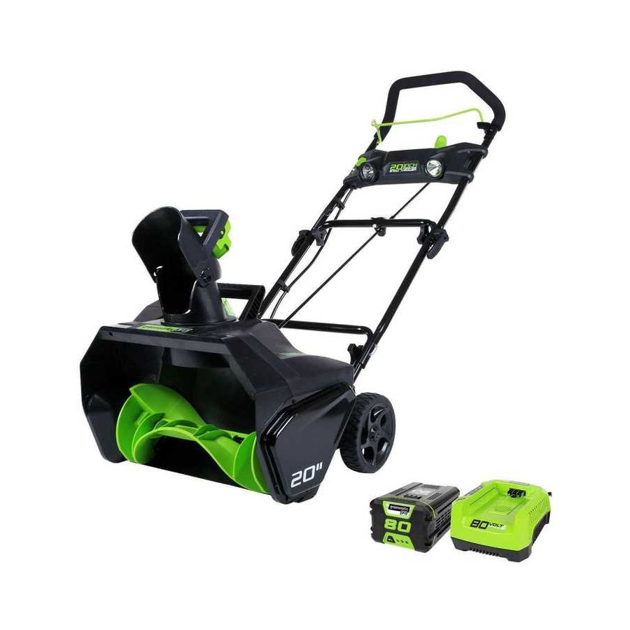
Safety switch button Upper handle chute control rod cam lock Chute deflector Middle handle Battery carrying or lifting compartment handle (For transport only) Lower handle discharge chute Wheel Impeller Scraper Greenworks Greenworks 80V charger 80V Battery (Model#:2901402) (Model#:2901302) Fig. 1... -
Page 9: Assembly
• Upper chute control rod • Lower chute control rod • Middle handle assembly • Chute deflector • Greenworks 80V Battery (Model#: 2901302) • Greenworks 80V Charger (Model#: 2901402) • (2) Cam locks • (2) Bolts • (4) Handle knobs •... - Page 10 ASSEMBLY iNSTRUCTiONS W A R N I N G Do not allow familiarity with this product to make you careless. Remember that a careless fraction of a second is sufficient to inflict serious injury. W A R N I N G Do not use any attachments or accessories not recommended by the manufacturer of this product.
- Page 11 ASSEMBLY iNSTRUCTiONS ASSEMBLING THE dIScHARGE cHUTE (See Figure 3) Push the chute deflector (1) until the latching tabs (2) on both sides click into the slots (3) and the posts (4) on both sides click into the keyed holes (5). Fig.
- Page 12 ASSEMBLY iNSTRUCTiONS INSTALLING THE cHUTE cONTROL ROd (See Figure 4) • Position the discharge chute (1) so that it faces forward. NOTE: Align the arrow (2) on the discharge chute with the arrow on the housing. (Fig. 4.1) • Align the holes (3) on the upper chute control rod (4) with the holes on the lower chute control rod (5).
- Page 13 ASSEMBLY iNSTRUCTiONS • Rotate the handle on the chute control rod to ensure that it moves in the same direction as the chute. (fig.4.4) Fig. 4.3 Fig. 4.4...
- Page 14 ASSEMBLY iNSTRUCTiONS TO INSTALL BATTERY PAcK (See Figure 5) • Open the battery compartment cover (1). • Slide the battery (2) down to lock it into position. The battery is fully inserted into the snow thrower when you hear an audible "click". •...
-
Page 15: Operation
OPERATiNG iNSTRUCTiONS POWERING ON ANd OFF (See Figure 6) • To power on, first press the safety switch button (1). • While pressing the safety switch button with one hand, use your other hand to simultaneously pull the bail switch (2) toward you. Once the machine powers on, release the safety switch button and proceed with operation. - Page 16 OPERATiNG iNSTRUCTiONS UTILIZING THE LEd LIGHTS (See Figure 7) • To utilize the LED lights (1) for night time snow removal, activate the LED light switch (2). NOTE: After you have finished using your snow thrower, remember to turn off the light switch. Fig.
- Page 17 OPERATiNG iNSTRUCTiONS AdjUSTING THE dIScHARGE cHUTE ANd cHUTE dEFLEcTOR (See Figure 8) • To adjust the discharge chute, rotate the handle (1) on the chute control rod in the direction that you wish to direct the snow stream. • To adjust the chute deflector (and therefore the height of the snow stream), squeeze the trigger (2) and raise or lower the chute deflector.
- Page 18 OPERATiNG iNSTRUCTiONS OPERATING TIPS W A R N I N G If the Snow Thrower hits a foreign object while it is in use, the object could be thrown in the direction of the operator or a bystander. Thrown objects could cause serious personal injury. Keep the area to be cleared free of all foreign objects that may be picked up and thrown by the impeller.
-
Page 19: Maintenance
MAiNTENANCE SERVIcING Servicing should be performed by a qualified technician. Replacement parts for this snow thrower must be identical to the parts that they replace. if repairs are necessary, contact the toll-free helpline, at 1-888-909-6757. Note: Identify the left and right sides of the snow thrower when standing in the normal operating position. W A R N I N G if the battery pack is installed into the snow thrower, the snow thrower could start accidentally while the operator is performing maintenance on it, which could cause serious personal injury. - Page 20 MAiNTENANCE REPLAcING THE ScRAPER (See Figure 9) The scraper is located at the bottom of the impeller housing. • Ensure that the battery is not installed in the tool. • Remove the screw (1) from each side plate that holds the scraper and 3 screws (2) from under the machine that secures the scraper to the machine.
- Page 21 MAiNTENANCE REPLAcING THE dRIVE BELT (See Figures 10) • Ensure that the battery is not installed in the tool. • Remove the 5 screws (1) that secure the left side plate (2) to the frame of the snow thrower. Remove the side cover. •...
- Page 22 MAiNTENANCE REPLAcING THE IMPELLER (See Figures 11-13) • Remove the 5 screws (1) that secure the right side cover (2) to the frame of the snow thrower. • Remove the nut (3). • Remove the 5 screws (4) that secure the left side cover (5) to the frame of the snow thrower. •...
-
Page 23: Troubleshooting
TROUBLESHOOTiNG PROBLEM POSSIBLE cAUSE SOLUTION Then handle is not The bolts are not properly Make sure the bolts are correctly installed in position. seated. through the handle bars. Check to see if the hand knobs are tight. Refer to Assembling the Handle section in this manual. -
Page 24: Warranty
(4) years against defects in materials, parts or workmanship. GREENWORKS™, at its own discretion will repair or replace any and all parts found to be defective, through normal use, free of charge to the customer. This warranty is valid only for... -
Page 25: Exploded View / Parts List
EXPLODED ViEW / PARTS LiST ITEM NO. PART NO. dEScRIPTION 332041205 Left side cover 32205877 Screw 329051205 Belt 32206575 Screw M5x8 3290250 Washer 311011205 front cover assembly 311021205 Rear cover assembly 361011205 Motor 332031205 Motor clamp 3410801 Wire clamp 3290135 Split pin 311031205 7"... - Page 26 EXPLODED ViEW / PARTS LiST ITEM NO. PART NO. dEScRIPTION 311011205 front cover assembly 332061205 Link block 341171205 impeller 339011205 Right driving block 34109100-12 Drive wheel 32217100 Washer 311111205 Left side plate 332111205 Bushing 339021205 Left driving block 332011205 Motor fixed plate 6-10 341011205 front cover...
- Page 27 EXPLODED ViEW / PARTS LiST ITEM NO. PART NO. dEScRIPTION 311021205 Rear cover assembly 341121205 Connecting base 341021205 Rear cover 311061205 Battery compartment assembly 311011009 Greenworks 80V battery 311011010 Greenworks 80V charger...
- Page 28 EXPLODED ViEW / PARTS LiST ITEM NO. PART NO. dEScRIPTION 311051205 Handle bar assembly 30-1 34136486-2 Safety switch button 30-2 33401229A Spring 30-3 341141205 faceplate 30-4 341201205 Switch pressure head 30-5 32205877 Screw 30-6 333011108 Parabolic reflector 30-7 342011108 Rubber gasket 30-8 341051108 Lamp screen...
- Page 29 TOLL-FREE HELPLINE: 1-888-90WORKS (888.909.6757) Rev: 01 (07-31-14) Printed in China on 100% recycle material...
Need help?
Do you have a question about the GW80VSNW200 and is the answer not in the manual?
Questions and answers
where can I get a light cover?
The parts list for the GreenWorks GW80VSNW200 includes a "Lower cover" (part no. 341151205) but does not specifically mention a "light cover." If you are referring to the "Lamp screen" (part no. 341051108), you may need to contact GreenWorks customer support or check their official website for purchasing options. You can reach their toll-free helpline at 1-888-90WORKS (888-909-6757).
This answer is automatically generated
How can i tell if the battery is charged?
The manual does not provide specific details on how to check if the GreenWorks GW80VSNW200 battery is charged. However, typically, GreenWorks 80V Lithium-ion batteries have LED indicators that show the charge level. You can check the battery's LED indicator lights or refer to the charger’s indicators to determine if the battery is fully charged.
This answer is automatically generated