Masport I5000 Installation Instructions Manual
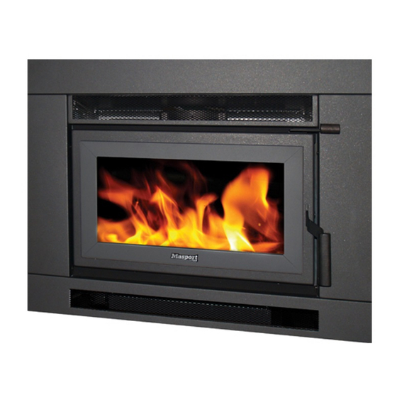
Insert fire, australian model
Hide thumbs
Also See for I5000:
- Installation instructions manual (14 pages) ,
- Installation instructions manual (9 pages)
Advertisement
MASPORT I5000 INSERT FIRE, AUSTRALIAN MODEL
INSTALLATION INSTRUCTIONS
Manufactured in New Zealand by:
GLEN DIMPLEX AUSTRALASIA LIMITED
PO Box 58-473 Botany
Auckland 2163
Ph: 0800 666 2824
Fax: 09274 8472
Email: sales@glendimplex.co.nz
Web: www.glendimplex.co.nz
19.04.2011
Distributed in Australia by:
GLEN DIMPLEX AUSTRALIA PTY LIMITED
Unit 2, 205 Abbotts Road, Dandenong South
Victoria, 3175
Ph: 1 300 566 816
Fax: 1 800 058 900
Email: sales@glendimplex.com.au
Web: www.glendimplex.com.au
Part. No. 593664
1
Advertisement
Table of Contents

Related Manuals for Masport I5000


Summary of Contents for Masport I5000
-
Page 1: Installation Instructions
MASPORT I5000 INSERT FIRE, AUSTRALIAN MODEL INSTALLATION INSTRUCTIONS Distributed in Australia by: Manufactured in New Zealand by: GLEN DIMPLEX AUSTRALIA PTY LIMITED GLEN DIMPLEX AUSTRALASIA LIMITED Unit 2, 205 Abbotts Road, Dandenong South PO Box 58-473 Botany Victoria, 3175 Auckland 2163... - Page 2 The model I5000 has been tested to demonstrate compliance with current general emission re- quirements in Australia, but some areas have stricter limits. So check before purchasing or install-...
- Page 3 INSTALLATION UNSAFE. NOTE The following instructions cover the installation of the model I5000 Insert Fire into a sound masonry fireplace which has an integral masonry chimney. Where such a chimney is not available, the heater can be installed into a timber framed structure provided that it is mounted in a special ‘build in’...
-
Page 4: Installation Requirements
INSTALLATION REQUIREMENTS FIREPLACE PREPARATION For a safe installation the following matters must be attended to: The masonry fireplace and chimney must be thoroughly cleaned and checked for soundness. The chimney must not connect to a second fireplace. The joint between the chimney face and the fireplace surround must be checked and sealed to prevent leakage if necessary. - Page 5 HEARTH REQUIREMENTS: You need an insulating floor protector (hearth). The minimum requirement for an insulating floor protector (hearth) is one layer of 6mm thick ‘PROMATECT H’, SUPALUX, or ETERPAN LD (or simi- lar with a heat transition coefficient of 5 W/m³ K), and a layer of tiles or slate. This will give a thick- ness of approximately 14mm, and the extension from the face of the glass must be at least 320mm (or 321mm from fireplace surround) if the floor protector is flush with the surrounding heat sensitive material.
-
Page 6: Installing The Firebox And Flue
INSTALLING THE FIREBOX AND FLUE Remove the door from the fire by opening it and lifting it up until the top pivot comes free and then lower the door until the bottom pivot comes free. You require a 150mm diameter flue. We recommend the use of the GDA flue kit for insert fires. Measure the fireplace recess and remove bricks as necessary to accept the firebox outer case. - Page 7 Bring the fascia in its upright position close to the fire and connect the earth lead to the tag on the lower end of the left hand fascia bracket. This is a quick connect push-on connection. Connect the three terminals at the end of the loom to the switch. See sketch for position of wires. Ensure the wiring loom rests in the notch behind the left hand fascia.
Need help?
Do you have a question about the I5000 and is the answer not in the manual?
Questions and answers